Transcription
Designing,Manufacturingand SupportingInnovativeApproaches to CleanWater Since 1863Eliminator Reverse Osmosis SystemsOperations & Maintenance Manual730 Commerce DriveVenice, Florida 34292 1-941-480-9101Crane Environmentalwww.cranewater.com 2011 Crane Co. All rights reserved.1EM0622-001
Table of ContentsCoverTable of ContentsIntroductionFigure 1: The Reverse Osmosis Membrane ElementFigure 2: OsmosisFigure 3: EquilibriumFigure 4: Reverse OsmosisSpecificationsTable 1: Eliminator I through IV SpecificationsTable 2: Eliminator V & VI SpecificationsTable 3: Eliminator Dual IV SpecificationsTable 4: Eliminator Dual VI SpecificationsGeneral Overview of System ComponentsTable 5: Centrifugal Pump Performance ChartFigure 5: Low Flow SwitchFigure 6: Low Flow Switch ConnectionTable 6: Feed Water RequirementsFigure 7: Eliminator VI System LayoutFigure 8: Spot Free Distribution System LayoutFigure 9: System P&ID (Eliminator IV)System InstallationSystem Start Up ProceduresScheduled MaintenanceFigure 10: Operation LogMembrane Removal and ReplacementTable 8: Troubleshooting endix A: CE2 Electronic Control ManualAppendix B: Booster Pump Operation & Maintenance ManualAppendix C: Activated Carbon Filter Valve SpecificationsAppendix D: Activated Carbon Filter Start Up ProceduresAppendix E: Technical Field Service InformationAppendix F: Terms and Conditions / Limited Warranty730 Commerce DriveVenice, Florida 34292 1-941-480-9101Crane Environmentalwww.cranewater.com 2011 Crane Co. All rights reserved.2EM0622-001
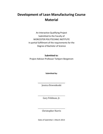
IntroductionReverse osmosis systems from Crane Environmental are designed to produce high qualitypermeate water from municipal and well water. The highest quality components and the latesttechnology are used in the production and design of our reverse osmosis systems.What is Reverse Osmosis?While ordinary filters use a screen to separate particles from water streams, a reverse osmosissystem uses a semi-permeable membrane to reject a high percentage of dissolved molecules.Only certain types of molecules, like water, can pass through the membrane. Other molecules,like salts, do not pass through the membrane and are left behind.What is a Semi-Permeable Membrane?A semi-permeable membrane is very similar to your skin. The membrane is made of thin, multilayered sheets with microscopic pores that let water pass through while acting as a barrier tostop dissolved particles like salt.Figure 1730 Commerce DriveVenice, Florida 34292 1-941-480-9101Crane Environmentalwww.cranewater.com 2011 Crane Co. All rights reserved.3EM0622-001
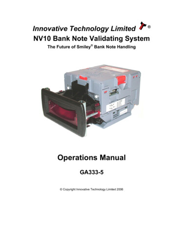
How Does Osmosis and Reverse Osmosis Work?As shown in Figure 2, under normal pressure water will pass from the side of the membrane withlower concentration to the side with the higher concentration to reach equilibrium.FIGURE 2: OSMOSISMEMBRANEWATERBRINEThe water flow stops when the applied pressure equals the osmotic pressure. The osmoticpressure is the pressure required to stop water flow and reach equilibrium.See Figure 3.Figure 3: EquilibriumOsmoticPressureBRINE730 Commerce DriveVenice, Florida 34292 1-941-480-9101WATERCrane Environmentalwww.cranewater.com 2011 Crane Co. All rights reserved.4EM0622-001
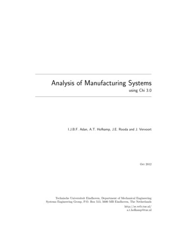
When the applied pressure exceeds the osmotic pressure, reverse osmosis will take place. Inreverse osmosis, water passes through the membrane to the dilute solution, leaving behinddissolved particles. This results in purified water in the permeate stream, often reducing thetotal dissolved solids over 99 percent. See Figure 4Figure 4: Reverse OsmosisAPPLIED PRESSUREBRINEWATERCrane Environmental systems use semi-permeable spiral wound, thin film compositemembranes to separate and remove dissolved solids, organic material, pyrogens, sub-microncolloidal matter, viruses, and bacteria from water. Feed water is delivered under pressure tothe membranes, where reverse osmosis takes place. Water permeates the minute pores of themembrane and is delivered as purified product water. The impurities in the water do not passthrough the membrane, and are instead concentrated in the reject stream that is flushed to thedrain.System Operating PressureThe system operating pressure is defined as the pressure required to produce the quantity ofpermeate water (product water) recommended for the specific application. This pressure ismeasured at the feed of the first membrane. It is important to understand the following basiccharacteristics of all reverse osmosis systems. The system operating pressure is determined bythree factors: the temperature of the feed water, the TDS of the feed water, and the type ofmembrane(s) installed in the system. As the feed water temperature decreases, and/or the feedwater TDS increases, the pressure required to produce a specific quantity of permeate waterincreases. Therefore, both the temperature and TDS of the feed water have a major impact onthe design and membrane selection of each reverse osmosis system.730 Commerce DriveVenice, Florida 34292 1-941-480-9101Crane Environmentalwww.cranewater.com 2011 Crane Co. All rights reserved.5EM0622-001
SpecificationsThe standard Eliminators available are Eliminator I through VI, the Eliminator Dual IV, and theEliminator Dual VI. Under recommended conditions, an Eliminator will produce 1440 gpd (1 gpm)@ a flux of 18.5 for each membrane. Lower feed water temperatures and/or higher feed waterTDS will result in a reeducation of feed water quantity. Cold water membranes are available tocompensate for colder feed water temperatures.Standard features available include: Automatic backwashing, activated carbon filter 5 micron prefilter Automatic inlet solenoid Stainless steel multi-stage centrifugal pump 230v/1ph/60hz ODP motor (three phase option is available) Aluminum wall mount frame (aluminum floor frame is optional) Stainless steel pump throttle value Physical water conditioner Fiberglass or stainless steel pressure vessels Standard or cold water, high rejection, TFC membranes Acrylic block permeate and concentrate flow metersst Liquid filled pressure gauges for prefilter out, 1 array feed and concentrate UL listed, programmable electronic control with an automatic low flow protectionsystem, a digital water quality meter, dry contacts for liquid level controls andpretreatment lockout, and function LED’s.Membrane RejectionMembrane rejection refers to the amount of total dissolved solids (TDS) rejected by themembrane, (expressed as a percentage). Membrane rejection is calculated using the followingformula:% of Rejection Feed TDS (ppm) – Permeate TDS (ppm) x 100Feed TDS (ppm)System RecoverySystem recovery is a ration between the amount of permeate water produced by the systemand the amount of feed water supplied to the system, (expressed as a percentage). Systemrecovery is calculated using the following formula:% of Recovery Permeate Water Flow Rate (gpm) x 100Feed Water Flow Rate (gpm)Membrane FluxMembrane flux is a relationship between the permeate production from a membrane, and thesurface area of that membrane.Membrane Flux Permeate Production (gpd)Membrane Surface Area (sq ft)730 Commerce DriveVenice, Florida 34292 1-941-480-9101Crane Environmentalwww.cranewater.com 2011 Crane Co. All rights reserved.6EM0622-001
TABLE 1Eliminator-I through Eliminator-IVCommon Part Numbers with DescriptionsPartPrefilter HousingPrefilter CartridgeInlet Solenoid – 115vInlet Solenoid – 220vPump/Motor Assembly60hz Standard60hz Low Pressure System60hz Three Phase *50hz Single Phase *50hz Three Phase *Pump Throttle ValvePhysical Water ConditionerConcentrate Control ValveConcentrate Pressure GaugeConcentrate Recycle Valve *Flush Solenoid *Part #HPO01SPFC02AGCV075BGCV075CDescription23”L X 5”D20”L X 2.75”D / 5 MicronNormally Closed, .75 In/Out,BrassMulti-Stage Centrifugal, S/S115-230v /1ph / 60hz / 1.5hp115-230v / 1ph / 60hz / 1.0hp230-460v / 3ph / 60hz / 1.5hp220v / 1ph / 50hz / 1.5hp380-415v / 3ph / 50hz / 1.5hpGlobe Valve, .75 In/Out, 316 S/STo Reduce Membrane Scaling Due To HardnessGlobe Valve, .75 In/Out, 316 S/S0-300 Psi, 2.5”D, Brass InternalsNeedle Valve, .5 In/Out, 316 S/SSame As Inlet GS01DGO02SBLV14-Additional PartsPartPressure Vessel, 4”X40”, F/GPressure Vessel, 4”X40”, S/SPressure Vessel Clamps, F/GPressure Vessel Clamps, S/SMembrane, 4”X40”, StandardMembrane, 4”X40”, Cold WaterMembrane, Extra Low Pressure *Concentrate Flow MeterPermeate Flow MeterActivated Carbon FilterPart#HEF64WCHES19CH-9PWHEA40ETT11ETT74ETT47 Permeate Production @ A Flux Of 18.5Average RejectionRecovery (Without Recycle)Minimum Feed Flow RequiredLength – Wall Frame / Floor FrameWidth – Wall Frame / Floor FrameHeight – Wall Frame / Floor FrameWeight – Wall Frame ( without ACF)Weight – Floor Frame ( with ACF)ELIM-IO1.0 GPM99.0 %20.0 %5.0 GPM35” / 35”15” / 32”55” / 65”150 LBS280 LBSELIM-II2.0 GPM99.0 %33.3 %6.0 GPM35” / 35”15” / 32”55” / 65”170 LBS300 LBSELIM-III3.0 GPM99.0 %42.9 %7.0 GPM35” / 35”15” / 32”55” / 65”190 LBS360 LBSELIM-IV4.0 GPM99.0 %50.0 %8.0 GPM35” / 35”15” / 32”55” / 65”210 LBS380 LBS* Optional Feature730 Commerce DriveVenice, Florida 34292 1-941-480-9101Crane Environmentalwww.cranewater.com 2011 Crane Co. All rights reserved.7EM0622-001
Table 2Eliminator-V and Eliminator-VICommon Part Numbers with DescriptionsPartPrefilter HousingPrefilter CartridgeInlet Solenoid – 220vPump/Motor Assembly60hz Standard60hz Three Phase *50hz Single Phase *50hz Three Phase *Pump Throttle ValvePhysical Water ConditionerConcentrate Control ValveConcentrate Pressure GaugeConcentrate Recycle Valve *Flush Solenoid *Part PLVGS03DGO02SBLV12GCV075CDescription12.75” X 7.25” (Big Blue)10”L X 4.5”D / 5 MicronNorm Closed, 1.0 In/Out, BrassMulti-Stage Centrifugal, S/S230v /1ph / 60hz / 3.0hp230-460v / 3ph / 60hz / 3.0hp220v / 1ph / 50hz / 3.0hp380-415v / 3ph / 50hz / 3.0hpGlobe Valve, 1.0 In/Out, 316 S/SReduces Membrane Scaling Due To HardnessGlobe Valve, 1.0 In/Out, 316 S/S0-300 Psi, 2.5”D, Brass InternalsNeedle Valve, .75 In/Out, 316 S/SNorm Closed, .75 In/Out, BrassAdditional PartsPartPressure Vessel, 4”X40”, F/GPressure Vessel, 4”X40”, S/SPressure Vessel Clamps, F/GPressure Vessel Clamps, S/SMembrane, 4”X40”, StandardMembrane, 4”X40”, Cold WaterMembrane, Extra Low Pressure *Concentrate Flow MeterPermeate Flow MeterActivated Carbon FilterPart#HEF64WCHES19CH-9PWHEA40ETT11ETT74ETT47 ermeate Production @ A Flux Of 18.5Average RejectionRecovery (Without Recycle)Minimum Feed Flow RequiredLength – Wall Frame / Floor FrameWidth – Wall Frame / Floor FrameHeight – Wall Frame / Floor FrameWeight – Wall Frame ( without ACF)Weight – Floor Frame ( with ACF)Eliminator-V5.0 GPM99.0 %41.7%12.0 GPM35” / 46”15” / 32”55” / 65”240 LBS410 LBSEliminator-VI6.0 GPM99.0 %42.9 %14.0 GPM35” / 46”15” / 32”55” / 65”260 LBS430 LBS* Optional Feature730 Commerce DriveVenice, Florida 34292 1-941-480-9101Crane Environmentalwww.cranewater.com 2011 Crane Co. All rights reserved.8EM0622-001
Table 3Eliminator Dual IVCommon Part Numbers with DescriptionsPartPrefilter Housing (2)Prefilter Cartridge (2)Inlet Solenoid – 220v (2)Pump/Motor Assembly (2)60hz Standard60hz Three Phase *50hz Single Phase *50hz Three Phase *Pump Throttle Valve (2)Physical Water Conditioner (2)Concentrate Control Valve (2)Concentrate Pressure Gauge (2)Concentrate Recycle ValveFlush SolenoidPart 0KSPLVGS01DGO02SBLV14GCV075CDescription23” X 5”20”L X 2.75”D / 5 MicronNorm Closed, .75 In/Out, BrassMulti-Stage Centrifugal, S/S230v /1ph / 60hz / 1.5hp230-460v / 3ph / 60hz / 1.5hp220v / 1ph / 50hz / 1.5hp380-415v / 3ph / 50hz / 1.5hpGlobe Valve, .75 In/Out, 316 S/SReduces Membrane Scaling Due To HardnessGlobe Valve, .75 In/Out, 316 S/S0-300 Psi, 2.5”D, Brass InternalsNeedle Valve, .5 In/Out, 316 S/SNorm Closed, .75 In/Out, BrassAdditional PartsPartPressure Vessel, 4”X40”, F/GPressure Vessel, 4”X40”, S/SPressure Vessel Clamps, F/GPressure Vessel Clamps, S/SMembrane, 4”X40”, StandardMembrane, 4”X40”, Cold WaterMembrane, Extra Low Pressure *Concentrate Flow Meter (2)Permeate Flow Meter (2)Activated Carbon Filter (2)Part#HEF64WCHES19CH-9PWHEA40ETT11ETT74ETT47 FAW2510-Eliminator Dual tor Dual IV4.0 Gpm Each Side99.0 %42.9 %8.0 Gpm Each Side46”32”65”750 LBSPermeate Production @ A Flux Of 18.5Average RejectionRecovery Each (Without Recycle)Minimum Feed Flow RequiredLength – Floor FrameWidth – Floor FrameHeight – Floor FrameWeight – Floor Frame ( With Two ACF’s)* OPTIONAL FEATURE730 Commerce DriveVenice, Florida 34292 1-941-480-9101Crane Environmentalwww.cranewater.com 2011 Crane Co. All rights reserved.9EM0622-001
Table 4Eliminator Dual VICommon Part Numbers with DescriptionsPartPrefilter Housing (2)Prefilter Cartridge (2)Inlet Solenoid – 220v (2)Pump/Motor Assembly (2)60hz Standard60hz Three Phase *50hz Single Phase *50hz Three Phase *Part #HPO05PFC03GCV100CPump Throttle Valve (2)Physical Water Conditioner ate Control Valve (2)Concentrate Pressure Gauge (2)Concentrate Recycle ValveFlush SolenoidDescription12.75” X 7.25” (BIG BLUE)10”L X 4.5”D / 5 MICRONNORM CLOSED, 1.0 IN/OUT, BRASSMULTI-STAGE CENTRIFUGAL, S/S230V /1PH / 60HZ / 3.0HP230-460V / 3PH / 60HZ / 3.0HP220V / 1PH / 50HZ / 3.0HP380-415V / 3PH / 50HZ / 3.0HPDPM120DPM150-GLOBE VALVE, 1.0 IN/OUT, 316 S/SREDUCES MEMBRANE SCALING DUE TO HARDNESSGLOBE VALVE, 1.0 IN/OUT, 316 S/S0-300 PSI, 2.5”D, BRASS INTERNALSNEEDLE VALVE, .75 IN/OUT, 316 S/SNORM CLOSED, .75 IN/OUT, BRASSAdditional PartsPartPressure Vessel, 4”X40”, F/GPressure Vessel, 4”X40”, S/SPressure Vessel Clamps, F/GPressure Vessel Clamps, S/SMembrane, 4”X40”, StandardMembrane, 4”X40”, Cold WaterMembrane, Xtra Low Press *Concentrate Flow Meter (2)Permeate Flow Meter (2)Activated Carbon Filter (2)Part#HEF64WCHES19CH-9PWHEA40ETT11ETT74ETT47 FAW2510-Eliminator Dual ator Dual VI6.0 GPM EACH SIDE99.0 %42.9 %14.0 GPM EACH SIDE46”32”65”800 LBSPermeate Production @ A Flux Of 18.5Average RejectionRecovery Each (Without Recycle)Minimum Feed Flow RequiredLength – Floor FrameWidth – Floor FrameHeight – Floor FrameWeight – Floor Frame ( With Two ACF’s)* Optional Feature730 Commerce DriveVenice, Florida 34292 1-941-480-9101Crane Environmentalwww.cranewater.com 2011 Crane Co. All rights reserved.10EM0622-001
General Overview of ComponentsActivated Carbon FilterAll Eliminator models are equipped with an automatic backwashing activated carbon filter (ACF)designed to remove oxidizing agents such as chlorine or chloramines from the feed water.Exposure to oxidizing agents will cause a continual degradation of the membrane, which willresult in poor permeate quality. It is recommended that the feed water after the ACF be testedonce per week for residual oxidizing agents. The carbon in the ACF must be replaced if anyresidual oxidizing agents are detected. Refer to Appendix B for information about the controlvalve on your ACF.PrefilterThe 5 micron prefilter located in the feed of your Eliminator is designed to remove smallamounts of suspended solids from the feed water. It is recommended that the feed watercartridge be replaced on a regular basis, depending on the feed water quality, (usually once permonth). A multimedia filter may be required for feed water containing higher levels ofsuspended solids.Inlet SolenoidYour Eliminator is equipped with an automatic inlet solenoid which will open when there is ademand for permeate (product) water. The inlet solenoid will be closed when there is nodemand for permeate water, which will prevent flow through the system when your Eliminatoris not in operation.High Pressure Booster PumpThe high pressure booster pump is a stainless steel, multi-stage centrifugal pump/motorassembly designed to provide the pressure and flow required for your Eliminator to produce theamount of permeate listed in Tables1, 2, 3, and 4 (pages 7-10).Pump Throttle ValveThe system operating pressure is the sum of the feed pressure and the booster pump pressure.The operating pressure of your Eliminator will decrease as the feed water temperatureincreases, which will result in an increase in pump flow due to the properties of the multi-stagecentrifugal pump. The pump throttle valve is used to adjust the pump flow to compensate fordifferences in feed water temperature. To understand this concept, refer to Table 5. Note thatwith a centrifugal pump, the pump flow will decrease as the operating pressure increased.The pump throttle valve should never be closed completelyPump Pressure120 PSI150 PSI180 PSI730 Commerce DriveVenice, Florida 34292 1-941-480-9101Table 5Centrifugal Pump Performance Chart1.0HP1.5 HP10.5 GPM12.0 GPM7.0 GPM9.0 GPM3.0 GPM6.5 GPMCrane Environmentalwww.cranewater.com 2011 Crane Co. All rights reserved.3.0 HP25.2 GPM20.5 GPM10.0 PSI11EM0622-001
Physical Water ConditionerThe patented physical water conditioner uses multiple reversing polarity magnetic fieldsto alter the natural scale forming characteristics of hard water borne minerals. Thesedissolved minerals consist of both positively and negatively charged ions, which, undernormal conditions, will bond together and form scale. If these altered minerals precipitatedue to excess concentration, they will not combine to cause scaling. The conditioner islocated in the plumbing just prior to the first membrane.Concentrate Control ValveThe concentrate control valve is located in the plumbing after the last membrane. Itsfunction is to increase the permeate production by raising the system back pressure.The concentrate control valve should never be closed completelyConcentrate Recycle Valve (optional)The concentrate recycle valve is plumbed from the feed side of the concentrate controlvalve to the suction side of the booster pump. Opening the recycle valve allows aportion of the concentrate water to go back through the system, increasing systemrecovery. This will also decrease permeate quality.Pressure GaugesAll eliminators are equipped with a prefilter out pressure gauge, a first array feed pressuregauge (operating pressure), and a concentrate pressure gauge. These gauges are required forproper set up, and effective troubleshooting.Permeate Flow meterThe permeate flow meter is an acrylic block flow meter that reads out in gallons perminute and liters per minute. The permeate flow meter is used to monitor the permeateproduction (good water) during system adjustment and during normal operation.Concentrate Flow meterThe concentrate flow meter is an acrylic block flow meter that reads out in gallons perminute and liters per minute. The concentrate flow meter is used to monitor theconcentrate flow (drain water) during system adjustment and during normal operation.Automatic Economy Permeate Flush (optional)Automatic Economy Permeate Flush is controlled by the CE2 control, and provides apermeate flush of the membranes on each system shut down. The economy permeateflush requires an on site connection from a pressurized permeate source. A carbon filtermust be included in the installation if an oxidizing agent is present in the permeate stream.Automatic Forward Fast Flush (optional)Automatic Forward Fast Flush is controlled by the CE2 control, which can be programmed toflush the membranes on a preset interval or upon each system shut down.730 Commerce DriveVenice, Florida 34292 1-941-480-9101Crane Environmentalwww.cranewater.com 2011 Crane Co. All rights reserved.12EM0622-001
CE2 Electronic ControlThe CE2 is a UL listed, programmable control with an automatic low flow protectionsystem, a digital water quality meter, dry contacts for pretreatment lock out and liquidlevel controls, an on/off switch, and function LED's. Forward fast flush or permeate flush areoptional.System Low Flow SwitchAll Eliminators are equipped with Low Flow Protection, which consists of a flow switchand the CE2 Electronic Control. The flow switch is located at the bottom (feed end) of theconcentrate flow meter, (See Figure 5 below), and provides an on/off signal to the CE2 control.The two leads from the flow switch are connected to the low flow pair of control contacts(fourth pair from top) on the upper right, side of the PC board located inside the CE2 ElectronicControl, (See Figure 6 below). During normal operation, when there is a demand for productwater, the inlet solenoid will open allowing water to flow through the system. When theconcentrate flow exceeds the minimum 1.5 gpm the flow switch will close which will signal thecontrol to introduce electrical power to the pump/motor assembly. The control provides a oneminute delay before electrical power is applied to the pump/motor. After the delay the systemwill start. If the concentrate flow drops below 1.5 gpm, the flow switch will open signaling thecontrol to interrupt the electrical power to the pump/motor assembly, the system will shutdown and the inlet solenoid will close. The control will automatically open the solenoid everyfive minutes as long as the demand for product water is not satisfied, allowing water to flowthrough the system. The flow switch will close when the concentrate flow exceeds the required1.5 gpm, which will signal the control to apply electrical power to the pump/motor assembly.Figure 5Flow Switch730 Commerce DriveVenice, Florida 34292 1-941-480-9101Figure 6Flow Switch ConnectionCrane Environmentalwww.cranewater.com 2011 Crane Co. All rights reserved.13EM0622-001
Feed Water RequirementsNothing has a greater effect on a reverse osmosis system than feed water quality. Forlasting performance it is important to supply the reverse osmosis system with the feedwater quality consistent with the recommended feed water quality shown in Table 5below. It is also important to feed the system the required amount of feed water, listedin Tables 1,2,3, and 4 (pages 7-10).Table 6Recommended Feed Water QualityHardnessFree ChlorineTDSpHMaximum TurbidityMaximum SDI 1 grain0.0 ppm 1000 ppm2 - 111.0 NTU5.0IronManganeseSilicaOrganicsTemperature 0.01 ppm 0.05 ppm 1.0 ppm 1 ppm35 F - 100 FThe Eliminator Systems' projected output is based on feed water with a TDS of 1000ppm or less and 77ºF (25ºC). Higher TDS and/or lower temperature will reduce systemproduction. The projected output can usually be reached by configuring the system with coldwater membranes, when feed water is colder than 77 F (25ºC). It is very important to meetfeed water requirements. Failure to do so will cause membranes to foul or scale. Providingthe proper pre-treatment and setting up the system correctly will extend the life of themembrane(s).Reverse osmosis causes the concentration of impurities to collect in the concentratestream. These impurities may precipitate (come out of solution) when theirconcentration reaches saturation. Precipitation can cause scaling and/or fouling of themembranes and must be prevented. Check your feed water chemistry. Provide thenecessary pretreatment, and/or reduce the system recovery as required. Consult withyour Crane Environmental service representative for pre-treatment recommendations.Fouled or scaled membranes are not covered by warranty730 Commerce DriveVenice, Florida 34292 1-941-480-9101Crane Environmentalwww.cranewater.com 2011 Crane Co. All rights reserved.14EM0622-001
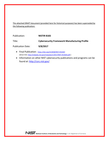
Figure 7Eliminator VI System PRESSUREVESSELSFLOW METERSCONCENTRATECONTROL VALVEPHYSICALWATERCONDITIONERPREFILTERINLET SOLENOIDPUMPMOTORASSEMBLYPUMPTHROTTLEVALVE730 Commerce DriveVenice, Florida 34292 1-941-480-9101Crane Environmentalwww.cranewater.com 2011 Crane Co. All rights reserved.15EM0622-001
FIGURE 8SPOT FREE DISTRIBUTION SYSTEM LAYOUTSPOT FREEDISTRIBUTIONSYSTEMPUMP/MOTORASSEMBLYSPOT FREEDISTRIBUTIONSYSTEMMANIFOLD730 Commerce DriveVenice, Florida 34292 1-941-480-9101Crane Environmentalwww.cranewater.com 2011 Crane Co. All rights reserved.16EM0622-001
System P&ID&/'hZ ϵ 730 Commerce DriveVenice, Florida 34292 1-941-480-9101Crane Environmentalwww.cranewater.com 2011 Crane Co. All rights reserved.17EM0622-001
System InstallationSite Requirements1. For best performance and reliability, your Eliminator should be located in a climate controlledroom. Freezing temperatures will cause damage to the unit.2. Wall mount systems must be installed on a wall that can support the weight of the unit. Thesystem must be level.3. Floor mount systems must be installed on a level pad. A vibration isolator is recommended.We recommend that a licensed electrician install your unit in accordance with all local andnational codes.Always verify the correct rotation of three phase motors. Reversal of any two power leadswill result in the reversal of the motor rotation.Electrical RequirementsGeneral power requirements for all standard Eliminators are listed below. Single phase unitscome equipped with the required power plugs. Three phase units require special hardconnections.1. The standard pump/motor assembly installed on the Eliminator-I, Eliminator-II,Eliminator-III, or Eliminator-IV is a 230V/1ph/60hz/1.5hp. The minimum requirement forthese systems is 230v/1ph/60hz, 20 amp service. The activated carbon filter requires aseparate 115v/1ph/60hz, 15 amp receptacle.2. The standard pump/motor assembly installed on the Eliminator-V or Eliminator-VI is a230v/1ph/60hz/3.0hp. The minimum requirement for these systems is a 230v/ph/60hz,30 amp service. The activated carbon filter requires a separate 115v/ph/60hz, 15 ampreceptacle.3. The Eliminator Dual IV is configured with two, 230,V1ph/60hz/1.5hp pump/motorassemblies, and two activated carbon filters. The minimum requirement for thesesystems is a 230v/1ph/60hz, 40 amp service. The activated carbon filters each require aseparate 115v/1ph/60hz, 15 amp receptacle.4. The Eliminator Dual VI is configured with two, 230v/1ph/60hz/3.0hp pump/motorassemblies, and two activated carbon filters. The minimum requirement for thesesystems is a 230v/1ph/60hz, 60 amp service. The activated carbon filters each require aseparate 115v/1ph/60hz, 15 amp receptacle.5. Your Eliminator will require an additional service if it is equipped with a Spot FreeDistribution System. The size of the service will have to be determined individually,because the horsepower and number of pump/motor assemblies supplied on the systemwill vary based on each application.We recommend that a licensed plumber install your Eliminator in accordance with all localand national codes.730 Commerce DriveVenice, Florida 34292 1-941-480-9101Crane Environmentalwww.cranewater.com 2011 Crane Co. All rights reserved.18EM0622-001
Plumbing RequirementsGeneral plumbing information for all standard Eliminators is listed below.1. The feed supply to your Eliminator must meet or exceed the feed requirementslisted in Tables 1, 2, 3, and 4 (pages 7-10). These requirements must be met inthe dynamic state, (system running).2. The feed line size must be equal to or larger than the input of the activatedcarbon filter.3. The drain line size must be equal to or larger than the concentrate output line.Any backpressure in the drain line must be overcome during operation by thebooster pump. A check valve must be installed on all drain lines plumbed in avertical configuration to prevent siphoning and excessive back pressure after the unitturns off.The drain line must be plumbed with an air gap. Do not feed the drain line downinside the drain.4. The permeate line size must be equal to or larger than the system permeateoutput line. Any backpressure in the permeate line must be overcome duringoperation by the booster pump. A check valve must be installed on all permeatelines plumbed in a vertical configuration to prevent siphoning and excessive backpressure after the unit turns off.The permeate line must be plumbed with an air gap. Do not feed the permeate linedown inside the permeate tank.ConnectionsAll Eliminators come from the factory pre-wired and pre-plumbed where ever possible.However, there will be some field connections required that cannot be avoided. All wallmount units will be shipped with the activated carbon filter and prefilter housingpackaged separately; therefore, they will require on site connections. Refer to the P&ID(Page 17) to determine the correct sequence of components. Floor mount units will beconfigured with the activated carbon filter and prefilter housing installed on the frame.The following plumbing connections will have to be made on site.Activated carbon filter inlet - 1" male NPTActivated carbon filter outlet (wall mount only) - 1" male NPTActivated carbon filter drain line - 5/8" ID flexible tubeRO permeate (Eliminator I and II) - 1/2" male NPTRO permeate (Eliminator III, VI, Dual IV & Dual VI) - 3/4" male NPTRO concentrate (all Eliminators) - 3/4' male NPTPermeate Atmospheric Storage Tank ConnectionsTo ease on site installation, Crane Environmental's atmospheric storage tank selections may beordered with the required upper and lower bulkhead fittings, and liquid level controls alreadyinstalled. It will be necessary to adjust the level controls for the desired operation based on therequired start and stop levels and differentials. Connect the permeate line to one of the upperbulkhead fittings. An additional upper bulkhead fitting is recommended to serve as an overflowto drain. The lower bulkhead fitting is used to supply the distribution system.730 Commerce DriveVenice, Florida 34292 1-941-480-9101Crane Environmentalwww.cranewater.com 2011 Crane Co. All rights reserved.19EM0622-001
Level control ConnectionsRed level controls (on wh
When the applied pressure exceeds the osmotic pressure, reverse osmosis will take place. In reverse osmosis, water passes through the membrane to the dilute solution, leaving behind dissolved particles. This results in purified water in the permeate stream, often reducing the total dissolved solids over 99 percent. See Figure 4