Transcription
Innovative Technology LimitedNV10 Bank Note Validating SystemThe Future of Smiley Bank Note HandlingOperations ManualGA333-5 Copyright Innovative Technology Limited 2006
NV10 Operations Manual – GA333-5Revision HistoryInnovative Technology LtdTitle:NV10 Engineers ManualDrawing No:Author:Format:Project:T.J. CrowleyMS WordDate:20/07/20052000IssueRel DateMod ByCommentsIssue 120/07/2005CCFirst draftIssue 208/08/2005RJSSecond DraftIssue 305/09/2005RJSInitial ReleaseIssue 431/08/2006WBEditorial UpdateIssue 529/05/2007MLCAddition of Belt Cleaning to 10.1WARNING:ONLY SUITABLY TRAINED PERSONNEL SHOULD CARRY OUT ANY WORKON THIS EQUIPMENT IN ACCORDANCE WITH ALL CURRENT LOCAL,NATIONAL AND INTERNATIONAL HEALTH AND SAFETY REGULATIONS.2 of 41 Copyright Innovative Technology Limited 2006
NV10 Operations Manual – GA333-5CONTENTSPage1: Introduction .52: Scope of Document .63: Environment and Power Requirements.74: General Description .85: NV10 User Interface .95.1:DIPswitch ---95.2: LED status codes. ------------------------------------------ 106: Machine Interface: Hardware.116.1:Interface Connector Pin Details -------------------------- 116.2:Input and Output Hardware ----------------------------- 126.3: Serial Interface Input and Outputs ---------------------- 127: Machine Interface: Protocols.137.1:Parallel input and output ----------------------------------- 137.2:Pulse Stream ---------------------------------------------- 137.3: Binary Output ------------------------------------------------ 147.4: Serial Input/Output – Baud Default 300 --------------- 157.5: Serial Input/Output - SI2 (Baud Default 9600) ------ 187.6: Smiley Secure Protocol – SSP ------------------------ 187.7: Multi-Drop Bus / Internal Communications Protocol (MDB/ICP) ---------------------------------- 207.8: CCTalk Protocol - CCT ------------------------------------ 217.9 Cash Code Serial Protocol – Ccnet --------------------- 227.10: Non Isolated Serial Protocol. (NIS) ------------------- 228: Updating Currency and Firmware .238.1: ITL Bank Note Validator Currency Manager --------- 238.2: NV10 – NV10 Copy ------------------------------------- 23Overview ------- 23Requirements - 23Start-up configuration ----------------------------------------- 23Cloning process. ----------------------------------------------- 24Firmware copy: ------------------------------------------------- 24Currency copy: ------------------------------------------------- 243 of 41 Copyright Innovative Technology Limited 2006
NV10 Operations Manual – GA333-59: Mechanical Installation.259.1: Changing or removing the bezels: ---------------------- 259.2: Fitting the bezel into a machine ------------------------- 259.3: Cash Box Interface ----------------------------------------- 2510: Routine Maintenance .2610.1: Cleaning --- 2610.2: Belt Changing ---------------------------------------------- 2811: Fault Finding Analysis.2912: Support Tools.3012.1: PC Programming Software (ITL Bank Note Validator Currency Manager) ------------------- 3012.2 Validator Programming System (DA3) ---------------- 3012.3 Internet Website support --------------------------------- 3012.4 E-mail Support ---------------------------------------------- 30Appendix A – Dimension Drawing .31Appendix B – Extended Bezel.32Appendix C – Cash Box Advice.33Appendix D - ESCROW Control .34Appendix E - Interface Tools DA1 - DA2 .35Appendix F - PC System specification.37Appendix G – Website Registration .384 of 41 Copyright Innovative Technology Limited 2006
NV10 Operations Manual – GA333-51: IntroductionThis manual describes the operation of the NV10 Bank note Validator as fitted with Firmware Version3.15 or greater.CAUTIONS THIS PRODUCT MUST BE FITTED WITH A 2 AMP FUSE BEFORE USE. THE NV10 VALIDATOR IS PIN FOR PIN COMPATIBLE WITH NV7/8/9, BUT NOTPIN FOR PIN COMPATIBLE WITH THE NV2/3/4/4X OR 5 SERIES PRODUCTS.We recommend that you study this manual as there are many new features permitting new uses andmore secure applications.If you do not understand any part of this manual please contact the factory, contact details are below,for assistance. In this way we may continue to improve our product.Innovative Technology Ltd.Derker StreetOldhamEnglandOL1 4EQTel: 44 (0) 161 626 9999Fax: 44 (0) 161 620 2090E-mailsupport@innovative-technology.co.ukWeb site www.innovative-technology.co.ukSmiley and the ITL Logo are international registered trademarks and they are the property of InnovativeTechnology Limited.Innovative Technology has a number of European and International Patents and Patents Pending protectingthis product. If you require further details please contact the factory.Innovative Technology is not responsible for any loss, harm, or damage caused by the installation and use ofthis product. This does not affect your local statutory rights. If in doubt please contact Innovative Technology fordetails of any changes5 of 41 Copyright Innovative Technology Limited 2006
NV10 Operations Manual – GA333-52: Scope of DocumentThis document is intended for those whose will: Design the NV10 into items of equipment. Build equipment using the NV10. Install equipment containing the NV10. Maintain equipment containing the NV10.Although information is included which will allow a degree of fault diagnosis and repair, it isrecommended that for all but simple mechanical repairs the unit be returned to an approved servicecentre for repair.CAUTIONS: NEVER EXCEED THE RECOMMENDED ENVIRONMENTAL AND ELECTRICAL LIMITS. DO NOT ATTEMPT TO LUBRICATE THE MECHANISMS AS THIS MAY AFFECT THE NOTETRANSPORT. DO NOT POLISH THE LENS AS THIS MAY ALTER THE OPTICAL CHARACTERISTICS. IF THE NV10 VALIDATOR IS DISASSEMBLED THE UNIT MUST BE RE-CALIBRATED/REINITIALISED, FOLLOWING RE-ASSEMBLY.Innovative Technology Ltd has a policy of continual product improvement. As a result the productssupplied may vary from the specification described here.6 of 41 Copyright Innovative Technology Limited 2006
NV10 Operations Manual – GA333-53: Environment and Power RequirementsEnvironmentMinimumoTemperatureHumidity 3 C5%Maximum 50oC95% Non condensingTable 1 - Environmental RequirementsCAUTIONS: IF THE INPUT VOLTAGE FALLS BELOW 11V THE NV10 MAY NOT OPERATECORRECTLY (WILL REJECT NOTES). THE AMBER STATUS LED AND FRONT BEZELLIGHTS WILL FLASH TO INDICATE INCORRECT CONDITIONS IT IS ESSENTIAL THAT THE POWER SUPPLY USED CAN SUPPLY AT LEAST 1.5AMPS.Electrical SupplySupply Voltage (V dc) Absolute LimitsMDB IF5 Version Supply VoltageSupply Ripple VoltageSupply Currents:StandbyValidatingPeakMinimumMaximum 11V 18V 15V 42V 0.25V @100HzTable 2 - Power Requirements7 of 41 Copyright Innovative Technology Limited 20060.35A1A1.5A
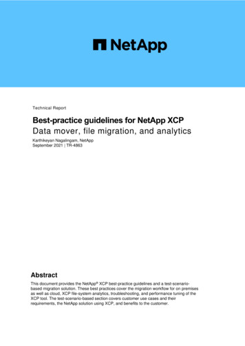
NV10 Operations Manual – GA333-54: General DescriptionNV10 Validator - the next generation of Smiley Bank Note validatorsThe NV10 Bank Note Validator is a compact note-validating machine (see figure 1), suitable for mostmoney machines. It will accept up to 15 different denominations of notes in the serial control mode,pulse mode and binary mode, 4 notes in parallel mode and will cope with different designs ofbanknotes having the same value such as are found in the United Kingdom.Note Path AccesButtonsBezel ReleaseCatchDIP SwitchesUser InterfaceDisplayUniversal BezelPA231Status LED’sFigure 1 – The NV10 and Universal Bezel PA231The NV10 Validator leaves the factory containing at least one currency data set so that it is readyfor immediate installation. If it is desired to change the currency data set this may be done usingeither the NV10 to NV10 currency cloning system or the PC based Currency Managementsoftware.New currencies and applications are being tested all the time, please refer to our web site or contactthe factory for information concerning specific currencies if they are not already included on ourapproved list.The NV10 has been designed for easy installation in most machines. The new stepped “smilingmouth” allows insertion of notes with one hand and simplifies the note handling mechanism.Interfacing the Validator is very simple, with the choice of the following protocols: Parallel open collector outputs Pulse stream output Binary Smiley Secure Protocol (SSP) secure serial communications Simple serial I/O communications MDB interface protocol CCTalk Extended Interface / USA Serial (NIS)8 of 41 Copyright Innovative Technology Limited 2006
NV10 Operations Manual – GA333-55: NV10 User InterfaceThe user interface with the NV9 is shown below (see figure 2). It is simply a set of four DIPswitchesand a RED LED, GREEN LED and an AMBER LED mounted on the side of the NV10. TheDIPswitches set the basic operating mode of the unit, while the LED’s indicate the operational statusof the NV10.AMBERREDGREENON1STATUS12341 2 3 44 ialFigure 2 – NV10 User Display and DIPswitches5.1:DIPswitch Settings.The four DIPswitches can be set to a combination of either upconfiguration required for the particular NV10.or downdepending on theSwitch 1 – SpareSwitch 1 currently has no function and is reserved for future use.Switch 2 – Extended OptionsThis switch is used to modify the behaviour of the selected machine interface. Details of the functionof this switch are covered in the interfaces’ description in this manual.Switches 3 and 4 – Machine Interface protocol selectionThese switches are used to select the machine interface to be used. The NV10 supports fourinterfaces, as shown below, (see table 1).9 of 41 Copyright Innovative Technology Limited 2006
NV10 Operations Manual – GA333-5Switch 3Switch SpecialTable 1 – Switch 3 and 4 Machine Interface SelectionThe details of the parallel, pulse and SSP can be found in the machine interface protocol section ofthis manual.Special ModesThe special interface depends on the firmware that is used in the NV10, the firmware shipped asstandard is CCTalk worldwide unless specified by order. The table below shows all the options thatcan be downloaded by the user:BINARYSIOMDBCCTalkSI2CCnetNIS & Unencrypted CCtalk –Available by request onlyInformation on each of these interfaces can be found in the ‘machine interfaces protocol section’ ofthis manual.5.2: LED status codes.The three status LED’s are located to the left of the DIPswitches on the right hand side of the unit andare used to indicate a variety of status signals.The red status is used to indicate system problems, while the green status indicates system health,these are described below in table 2.LED StatusSlow flashing GREEN led Heartbeat(Slow 1 second period).On Start Up - Flashing RED one second period.During operation - Flashing RED one secondperiodOn Start Up Fast - Flashing Red (fast halfsecond period).During operation- Flashing Red (fast halfsecond period).Permanent REDFlashing AMBER and bezel lightsDescriptionIn normal RUN operation, when the NV10 is ready toread a note, the green status led will flash slowly("Heartbeat") to signal a “healthy” status.Firmware FailNV10 has a Transportation error, somewhere in thenote pathDataset failNV10 cannot calibrate, sensor(s) may be blocked.Memory has been corruptedPower supply is incorrect, check specificationTable 2 - LED Status Codes10 of 41 Copyright Innovative Technology Limited 2006
NV10 Operations Manual – GA333-56: Machine Interface: Hardware.The NV10 interface connector is located on the left side of the unit. It has 16 pins (see figure 3), twoare used for the 0v and 12v power supply and there are five outputs and five inputs, the remainingfour pins are reserved for future use. An example mating connector is Molex Part No: 39-51-2160Interface ConnectorFigure 3 - Interface Connecter6.1:Interface Connector Pin DetailsThe interface connector pins details are described below (see table 3); they have an IDC16-pin 0.1"pitch header with 2 rows of 8 pins.PinName1Vend 12345Vend 2Vend 3Vend 4Inhibit 16789Inhibit 2Inhibit 3Inhibit 4Busy10Escrow111213141516Factory Use OnlyFactory Use OnlyFactory Use OnlyFactory Use Only Vin0VDescriptionOpen Collector Output. Function changes depending on MachineInterface Protocol. (See individual interface descriptions for details)Also the Pulse Stream outputAlso the serial Output pin in SSP Serial Mode, and other serial modesOpen Collector Outputs.Function changes depending on Machine Interface Protocol.(See individual interface descriptions for details)Inhibit channel 1 by holding this pin HIGH. To Enable a channel theinhibit must be held LOW Also the serial Input pin in SSP Serial Mode,and other serial modesInhibit channel 2 by holding this pin HIGHInhibit channel 3 by holding this pin HIGHInhibit channel 4 by holding this pin HIGHNV9 is validating and stacking output. Active low while the NV10 isreading, transporting or stacking a note.Operate Escrow function by holding LOW (see Appendix D for fulldetails)Do Not ConnectDo Not ConnectDo Not ConnectDo Not ConnectNominal 12V DC supply0V SupplyTable 3 - 16 Pin Connector Details11 of 41 Copyright Innovative Technology Limited 2006
NV10 Operations Manual – GA333-56.2:Input and Output Hardware CircuitsCAUTION: THE OUTPUT LOW SIGNAL IS AFFECTED BY THE VALUE OF THE PULL UPRESISTOR ON THE HOST MACHINE INTERFACE. ENSURE YOUR SIGNAL LOWLEVELS COMPLY WITH THE 74HC CMOS SERIES SPECIFICATION FOR RELIABLEOPERATION, (SEE FIGURE 4). 5V10KOutput1K0InputµPµP0V0VFigure 4 - Input and Output CircuitAll outputs are open collector transistors.All Inputs are held high to internal 5v via 10KΩ. The input structure is a CMOS gate with antistatic protection fitted.Interface Logic levelsLogic LowLogic HighInputs0V Low 0.50.6V 3.7V High 12VPull up voltage of host interfaceOutputs with 2K2Ω pull upMaximum Current Sink50mA per outputTable 4- Interface Logic Levels6.3: Serial Interface Input and OutputsCAUTION: THE SERIAL INTERFACES WILL ONLY WORK IF THE RELEVANT INTERFACESOFTWARE IS CORRECTLY INSTALLED.NameDescriptionSSP TxDSSP RxDVend 1Inhibit 1Table 5 - Serial Interface Inputs and Outputs12 of 41 Copyright Innovative Technology Limited 2006
NV10 Operations Manual – GA333-57: Machine Interface: ProtocolsThe NV10 is set to the required Protocol/Interface, by setting the DIPswitches on the right hand sideof the NV10 to the position detailed below:7.1:Parallel input and outputTo use parallel output for 4 notes/channel acceptance, DIPswitches 3 and 4 must be set down. Thismode is selectable regardless of which extended interface is programmed into the validator(Dipswitch 2 is not functional in this mode)Vend Signals: (Pins 1 to 4). The four channels have their own individual outputs. If a note isrecognised then the relevant channel line is set low for 100 3 milliseconds. Pulses outside theselimits should be rejected as a precaution against false triggering due to noise.Busy Output: (Pin 9). This is a general-purpose busy signal. It is active low while the NV10 is inoperation.Escrow Control (Pin 10) Hold this pin low to enable the single note escrow function(see Appendix D ):If the host machine aborts the transaction by setting the corresponding inhibit input high, the note isreturned immediately.The host machine can force the return of the note to the customer by setting the inhibit line high, atany time before the end of the 30 second time-out. Setting high, all the inhibits, causes a note reject.In the event of a note being forcibly removed from the mouth of the NV10 during the 30-secondinterval, the NV10 will go out of service for 45 seconds.Inhibit Operation(Pins 5 to 8) Channels 1 to 4 have their own inhibit input to allow the host machine to refuse specifiednotes. To inhibit a channel, the relevant inhibit input must be held high. To enable a channel thecorresponding inhibits must be latched low so that notes may be accepted.If all four inhibits are high simultaneously then the NV10 will not read in any notes. In this mode, if anote is inserted the motor will run in reverse preventing the insertion of a note and the bezel will notilluminate.All four inhibits may be connected together to create a 'global' inhibit. In this way the NV10 may bebrought in and out of operation by the host machine.7.2:Pulse Stream OutputTo use pulse stream output for acceptance of up to 16 channel / note acceptance, DIPswitch 3 mustbe down and DIPswitch 4 must be up. This mode is selectable regardless of which extended interfaceis programmed into the validatorVend Signal (Pins 1): When a note is recognised vend 1 will pulse a pre set number times, thenumber of pulses and the timing is set in the NV10 currency manager program (and set to defaultvalues with supplied dataset).DIPswitch 2: The number of pulses is multiplied by a factor of four for USA Dollar datasets,depending on the position of switch 2. If the switch is down then the number of pulses is asprogrammed in the dataset output. If the switch is up then four times this number of pulses is output.Busy Output: (Pin 9). This is a general-purpose busy signal. It is active low while the NV10 is inoperation.Escrow Control: (Pin 10) Hold this pin low to enable the single note escrow function(see Appendix D ):If the host machine aborts the transaction by setting the corresponding inhibit input high, the note isreturned immediately.The host machine can force the return of the note to the customer by setting the inhibit line high, atany time before the end of the 30 second time-out. Setting high, all the inhibits, causes a note reject.13 of 41 Copyright Innovative Technology Limited 2006
NV10 Operations Manual – GA333-5In the event of a note being forcibly removed from the mouth of the NV10 during the 30-secondinterval, the NV10 will go out of service for 45 seconds.Inhibit Operation: (Pins 5 to 8) Channels 1 to 4 have their own individual inhibit input to allow thehost machine to refuse specified values of notes. To inhibit a channel, the relevant inhibit input mustbe held high. To enable a channel the corresponding inhibit line must be latched low so that notesmay be accepted.If all four inhibits are high simultaneously then the NV10will not read in any notes. All four inhibits maybe connected together to create a 'global' inhibit. In this way the NV10 may be brought in and out ofoperation by the host machine.Note: Channels higher than four cannot be individually inhibited, but will be globally inhibitedif inhibits 1 to 4 are inhibited.7.3: Binary OutputTo use Binary mode DIPswitches 3 and 4 must be in the Up position to select ‘Special’ mode on thevalidator and the BIN option of the interface firmware must be loaded into the NV9.(Dipswitch 2 is not functional in this mode).In the event that the machine needs more than 4 notes to be recognised, but the host machinecannot take advantage of the serial communication methods then the NV10 can be set to give abinary pattern output on the four parallel output pins.If the NV10 is set to binary mode it will issue the vend signals as a binary pattern on the paralleloutputs for 100 3ms. In this way a maximum of 15 different notes can be accepted and 4 notesindividually inhibited.Vend Signals (Pins 1 to 4). The four channels have their own individual outputs. If a note isrecognised then the binary representation of the channel number will be pulled low for 100 3ms.Pulses outside these limits will be rejected as a precaution against false triggering due to noise.Busy Output: (Pin 9). This is a general-purpose busy signal. It is active low while the NV10 is inoperation.Escrow Control (Pin 10) Hold this pin low to enable the single note escrow function(see Appendix D ):If the host machine aborts the transaction by setting the corresponding inhibit input high, the note isreturned immediately.The host machine can force the return of the note to the customer by setting the inhibit line high, atany time before the end of the 30 second time-out. Setting high, all the inhibits, causes a note reject.In the event of a note being forcibly removed from the mouth of the NV10 during the 30-secondinterval, the NV10 will go out of service for 45 seconds.Inhibit Operation: (Pins 5 to 8) Channels 1 to 4 have their individual inhibit input to allow the hostmachine to refuse specified notes. To inhibit a channel, the relevant inhibit input must be held high.To enable a channel the corresponding inhibit line must be latched low so that notes may beaccepted.If all four inhibits are high simultaneously the NV10 will not read notes. All 4 inhibits connectedtogether create a 'global' inhibit. This way the NV10 may be brought in and out of operation by thehost machine.Note: Channels higher than four cannot be individually inhibited, but will be globally inhibitedif inhibits 1 to 4 are inhibited.14 of 41 Copyright Innovative Technology Limited 2006
NV10 Operations Manual – GA333-57.4: Serial Input/Output – Baud Default 300Existing Smiley NV4 users may already be using the serial input/output facility. The NV10 Validatoralso supports this system. However this interface is not recommended for new designs, the Smiley Secure Protocol SSP interface is recommended.CAUTION: THE NV10 DOES NOT SUPPORT THE SIMPLE SERIAL DATA OUT ONLY MODE ASAVAILABLE ON NV4, NV3 and NV2. IT ONLY SUPPORTS THE SERIAL DATAINPUT/OUTPUT MODE. THE HOST MACHINE DOES NOT ECHO MESSAGES BACK TO THE VALIDATOR. THE NV10 DOES NOT OPERATE IN TRUE RS232 MODE. THE NV10 WILL NOT ENABLE IN SERIAL I/O MODE IF INHIBIT 3 LINE IS HELD LOWON POWER UPNOTE: The NV9 will not be enabled in serial I/O mode if Inhibit 3 line is held low when the unitis powered upTo use simple serial mode DIPswitches 3 and 4 must be in the Up position to select ‘Special’ modeon the validator and the SIO option of the interface firmware must be loaded into the NV9.(Dipswitch 2 is not functional in this mode)Commands are provided to fully control the operation of the validator. The notes to be accepted andrejected can be set and a single note escrow mode can be enabled. In simple serial mode single bytecommands are transmitted to the Validator, the Validator echoes each valid command it receives.The Host machine needs to wait for an echo to a command it sends or for 1 second after sending acommand before it sends its next command. If it does not receive an echo response and times outafter 1 second then it should retry sending the previous command.The serial I/O mode supports two baud rates; 300 baud when Inhibit 2 is pulled high or left floating atpower up and 9600 Baud rate when Inhibit 2 line is held low at power up. The data is formatted asfollows (see figure 6):1-start bit - 8 data bits - 2 stop bits - 300 baudVend 1(pin 1)IdleStartBit 0Bit 100Bit 23.3ms1Bit 3Bit 4Bit 5Bit 6Bit 7Stop01000 20decStopIdleFigure- 5 Typical Serial Output Transmission of the value 20 (decimal), Note Not Recognized15 of 41 Copyright Innovative Technology Limited 2006
NV10 Operations Manual – GA333-5The NV10 will receive and transmit the following event codes:Recognised Receive Codes to NV10Transmitted codes from NV10MESSAGEDECIMAL VALUEMESSAGEDECIMAL VALUEInhibit C1131Note Accept on C11Inhibit C2Inhibit C3Inhibit C4Inhibit C5Inhibit C6Inhibit C7Inhibit C8Inhibit C9Inhibit C10Inhibit C11Inhibit C12Inhibit C13Inhibit C14Inhibit C15Inhibit C16Un-inhibit C1Un-inhibit C2Un-inhibit C3Un-inhibit C4Un-inhibit C5Un-inhibit C6Un-inhibit C7Un-inhibit C8Un-inhibit C9Un-inhibit C10Un-inhibit C11Un-inhibit C12Un-inhibit C13Un-inhibit C14Un-inhibit C15Un-inhibit C16Enable serial escrow modeDisable serial escrow modeAccept EscrowReject EscrowStatusEnable 71172173182184Note Accept on C2Note Accept on C3Note Accept on C4Note Accept on C5Note Accept on C6Note Accept on C7Note Accept on C8Note Accept on C9Note Accept on C10Note Accept on C11Note Accept on C12Note Accept on C13Note Accept on C14Note Accept on C15Note Accept on C16Note Not RecognisedMechanism running isable all185Disable escrow timeout190Enable escrow timeout191Channel 5 Note Rejected (fraud channel)STACKER Full or JammedAbort During EscrowNote may have been taken to clear jamValidator BusyValidator Not BusyCommand ErrorTable 6 - Receive and Transmit CodesExample transactions are shown below (see table 7).16 of 41 Copyright Innovative Technology Limited 2006
NV10 Operations Manual – GA333-5Table 7 - Example ProtocolsEventNote entered into validatorNote Accepted Channel 2Note entered into validatorNote not recognisedValidator has returned noteSoftware Inhibit Channel 4Software Enable Channel 4ValidatorValidator BusyValidator ReadyAccept on Channel 2Validator BusyValidator ReadyNote not recognisedValidator ReadyInhibit C4Channel 4 InhibitedUninhibit C4Channel 4 InhibitedStatus ReportStatus RequestedInhibit status Channels 1-8Inhibit status Channels 916Escrow On ( 1) / Off ( 0)3 byte status messageTurn on Escrow ModeNote accept in EscrowModeNote entered into validatorNote Accepted Channel 2Decimal Value120121212012120121134134154154182182byte 1byte 2byte 3170Escrow Mode Enabled170Validator BusyValidator ReadyAccept on Channel 21201212172Accept EscrowAccept on Channel 2172217 of 41 Copyright Innovative Technology Limited 2006HostInhibit C4Uninhibit C4Status RequestEnable EscrowModeAccept Note inEscrow
NV10 Operations Manual – GA333-57.5: Serial Input/Output - SI2 (Baud Default 9600)This mode is identical to the SIO mode detailed in chapter 7.4 with the exception of the Baud rateused and the data format.-Only 9600 baud rate is available.-Inhibit 2 has no function.-All Transmit and Receive codes and Example protocols are the same as in Chapter 7.4 (Seetables 6 and 7 above)The data is formatted as follows:1-start bit - 8 data bits - 1 stop bit - 9600 baudVend 1(pin 1)IdleStartBit 0Bit 100Bit 23.3ms1Bit 3Bit 4Bit 5Bit 6Bit 7Stop01000 20decIdleFigure- 6 Typical Serial Output Transmission of the value 20 (decimal), Note Not Recognized7.6: Smiley Secure Protocol – SSPNote: Please refer to the Smiley Secure Protocol (SSP) Specification (ITL Drawing GA138) on theweb site for full details of this Protocol.To use SSP mode DIPswitch 3 must be set up and DIPswitch 4 must be set down. This mode isselectable regardless of which ext
Innovative Technology Ltd. Derker Street Oldham England OL1 4EQ Tel: 44 (0) 161 626 9999 Fax: 44 (0) 161 620 2090 E-mail support@innovative-technology.co.uk Web site www.innovative-technology.co.uk Smiley and the ITL Logo are international registered trademarks and they are the property of Innovative Technology Limited.