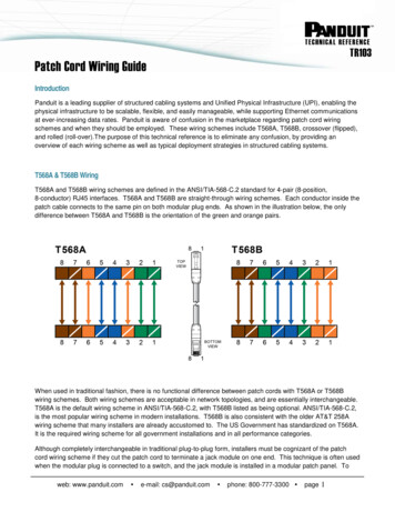
Transcription
Service Application ManualSAM Chapter 620-37Section 6ATERMINAL MARKINGS AND INTERNAL WIRING DIAGRAMS SINGLE PHASE ANDPOLYPHASE MOTORS MEETING NEMA STANDARDSINTRODUCTIONThe following represents the most up-to-date information on motor terminal marking for proper connectionto power source for all alternating current motors manufactured in accordance with standards adopted bythe National Electrical Manufacturers’ Association.In addition, this section contains important data covering internal wiring to motor terminals which willprove invaluable to the Refrigeration Service Engineer in solving motor problems.The source of this information is Part 2 of the NEMA Standards Publication, for which reprint permissionwas granted RSES by the National Electrical Manufacturers' Association.MG 1-2.01 LOCATION OF TERMINAL MARKINGSTerminal markings shall be placed on or directly adjacent to terminals to which connections must bemade from outside circuits or from auxiliary devices which must be disconnected for shipment. Whereverspecified, color coding may be used instead of the usual letter and numeral marking.*MG 1-2.02 TERMINAL MARKINGSA combination of capital letters or symbols and an arabic numeral shall be used to indicate the characteror function of the windings which are brought to the terminal.*The following letters and symbols shall be used for motors and generators and their auxiliary deviceswhen they are included within or mounted on the machine.*Resistance (shunt field adjusting)–V1, V2, V3, etc.Shunt braking resistor–DR1, DR2, DR3, DR4, etc.Space heaters–H1, H2, H3, H4, etc.‡Stator –T1, T2, T3, T4, etc.Starting switch–K.Terminal protector–P1, P2, P3, P4, etc.Equalizing lead– (equality sign).Neutral connection–Terminal letter with numeral 0.For the significance of the arabic numeral, see MG 1-2.20 for alternating-current machines.‡For alternating-current machines only.Armature–A1, A2, A3, A4, etc.Brake–B1, B2, B3, B4, etc.Alternating-current rotor windings (collector rings) ‡–M1, M2, M3, M4, etc.Capacitor–J1, J2, J3, J4, etc.Control signal lead attached to commutating winding–C.1
Service Application ManualSAM Chapter 620-37Section 6ATERMINAL MARKINGS AND INTERNAL WIRING DIAGRAMS SINGLE PHASE ANDPOLYPHASE MOTORS MEETING NEMA STANDARDSDynamic braking resistor–BR1, BR2, BR3, BR4, etc.Field (series)–S1, S2, S3, S4, etc.Field (shunt)–F1, F2, F3, F4, etc.Line–L1, L2, L3, L4, etc.Magnetizing winding (for initial and maintenance magnetization and demagnetization of permanentmagnetic fields)–E1, E2, E3, E4, etc. (NOTE–E1, E3, or other odd-numbered terminals should beattached to the positive terminal of the magnetizing power supply for magnetization and to the negativeterminal for demagnetization.) Resistance (armature and miscellaneous)–R1, R2, R3, R4, etc.* Approved as NEMA Standard 11-16-1967‡Approved as Authorized Engineering Information 11-16-67 Added as NEMA Standard 11-16-68ALTERNATING-CURRENT MOTORS AND GENERATORSMG 1-2.20 Numerals on Terminals Of Alternating-Current Polyphase MachinesA. SYNCHRONOUS MACHINESThe numerals 1, 2, 3, etc., indicate the order in which the voltages at the terminals reach theirmaximum positive values (phase sequence) with clockwise shaft rotation when facing theconnection end of the coil windings: hence, for counterclockwise shaft rotation (not standard)when facing the same end, the phase sequence will be 1, 3, 2.†B. INDUCTION MACHINESTerminal markings of polyphase induction machines are not related to the direction of rotation.†* Approved as NEMA Standard 11-16-1967†Approved as Authorized Engineering Information 11-16-1967MG 1-2.21 Definition Of Phase SequencePhase sequence is the order in which the voltages successively reach their maximum positive valuesbetween terminals.*MG 1-2.22 Phase SequenceThe order of numerals on terminal leads does not necessarily indicate the phase sequence, but the phasesequence is determined by the direction of shaft rotation relative to the connection end of the coilwinding.†MG 1-2.23 Direction Of Rotation Of VectorsVector diagrams shall be shown so that advance in phase of one vector with respect to another is in thecounterclockwise direction.2
Service Application ManualSAM Chapter 620-37Section 6ATERMINAL MARKINGS AND INTERNAL WIRING DIAGRAMS SINGLE PHASE ANDPOLYPHASE MOTORS MEETING NEMA STANDARDSSee Fig. 2-11 in which vector 1 is 120 degrees in advance of vector 2 and the phase sequence is 1, 2, 3.(See MG 1-2.21.)*MG 1-2.24 Direction Of RotationThe standard direction of rotation for alternating generators is clockwise when facing the end of themachine opposite the drive.*The direction of rotation of a generator mounted as a part of an engine-generator set is usuallycounterclockwise when facing the end opposite the drive.†The standard direction of rotation for all alternating-current single-phase motors, all synchronous motors,and all universal motors shall be counterclockwise when facing the end of the machine opposite thedrive.*MG 1-2.25 Reversal Of Rotation, Polarity And Phase SequenceAlternating-current generators driven counterclockwise when facing the connection end of the coilwindings will generate without change in connections, but the terminal phase sequence will be 1, 3, 2.†Synchronous condensers and synchronous motors may be operated with counterclockwise shaft rotationviewed from the connection end of the coil windings by connecting them to leads in which the phasesequence is 1, 2, 3, in the following manner:†Power leads. 1, 2, 3Machine terminals.1, 3, 2ALTERNATING-CURRENT GENERATORS AND SYNCHRONOUS MOTORSMG 1-2.30 Connections And Terminal Markings–Alternating-Current Generators And SynchronousMotors–One, Two, And Three PhaseThe alternating-current windings of three-phase alternating-current generators and synchronous motorsshall have terminal markings as given in MG 1-2.61 for three-phase single-speed induction motors.*The alternating-current windings of two-phase alternating-current generators and synchronous motorsshall have terminal markings as given in MG 1-2.66 for two-phase single-speed induction motors.*The alternating-current windings of single-phase alternating-current generators and synchronous motorsshall have terminal markings as given in Fig. 2-12.*3
Service Application ManualSAM Chapter 620-37Section 6ATERMINAL MARKINGS AND INTERNAL WIRING DIAGRAMS SINGLE PHASE ANDPOLYPHASE MOTORS MEETING NEMA STANDARDSThe terminal markings of direct-current field windings shall be F1 and F2.*NOTE:See MG 1-2.02 for terminal letters assigned to different types of windings and MG 1-2.20for the significance of the numerals.†SINGLE-PHASE MOTORSMG 1-2.40 GeneralA. DUAL VOLTAGERegardless of type, when a single-phase motor is reconnectible series-parallel for dual voltage,the terminal marking shall be determined as follows:*For the purpose of assigning terminal markings, the main winding is assumed to be divided intotwo halves, and T1 and T2 should be assigned to one half and T3 and T4 to the other half.*For the purpose of assigning terminal markings, the auxiliary winding (if present) is assumed tobe divided into two halves, and T5 and T6 should be assigned to one half and T7 and T8 to theother half.*Polarities shall be established so that the standard direction of rotation (counterclockwise facingthe end opposite the drive) is obtained when the main winding terminal T4 and the auxiliarywinding terminal T5 are joined or when an equivalent circuit connection is made between themain and auxiliary winding.*The terminal marking arrangement is shown diagrammatically in Fig. 2-13.*4
Service Application ManualSAM Chapter 620-37Section 6ATERMINAL MARKINGS AND INTERNAL WIRING DIAGRAMS SINGLE PHASE ANDPOLYPHASE MOTORS MEETING NEMA STANDARDSB. SINGLE VOLTAGEIf a single-phase motor is single voltage or if either winding is intended for only one voltage, theterminal marking shall be determined as follows.*T1 and T4 shall be assigned to the main winding and T5 and T8 to the auxiliary winding (ifpresent) with the polarity arrangement such that the standard direction of rotation is obtained if T4and T5 are joined to one line and T1 and T8 to the other.*The terminal marking arrangement is shown diagrammatically in Fig. 2-14.*5
Service Application ManualSAM Chapter 620-37Section 6ATERMINAL MARKINGS AND INTERNAL WIRING DIAGRAMS SINGLE PHASE ANDPOLYPHASE MOTORS MEETING NEMA STANDARDSNOTE:It has been found to be impracticable to follow this standard for the terminalmarkings of some definite-purpose motors. See Part 18.†NOTE:No general standards have been developed for terminal markings of multispeedmotors because of the great variety of methods employed to obtain multiplespeeds.†MG 1-2.41 Terminal Markings Identified By ColorWhen single-phase motors use lead colors instead of letter and number markings to identify the leads,the color assignment shall be determined from the owT5–BlackT8–RedP1–No color assignedP2–BrownNOTE:It has been found to be impracticable to follow this standard for the lead markings ofsome definite-purpose motors. See Part 18.†MG 1-2.42 Auxiliary Devices Within MotorThe presence of an auxiliary device or devices, such as a capacitor, starting switch, terminal protector,etc., permanently connected in series between the motor terminal and the part of the winding to which itultimately connects shall not affect the marking unless a terminal is provided at the junction.*Where a terminal is provided at the junction, the terminal marking of this junction shall be determined bythe part of the winding to which it is connected. Any other terminals connected to this auxiliary deviceshall be identified by a letter indicating the auxiliary device within the motor to which the terminal isconnected.*MG 1-2.43 Auxiliary Devices External To MotorWhere the capacitors, resistors, inductors, transformers or other auxiliary devices are housed separatelyfrom the motor, the terminal markings shall be those established for the device.*6
Service Application ManualSAM Chapter 620-37Section 6ATERMINAL MARKINGS AND INTERNAL WIRING DIAGRAMS SINGLE PHASE ANDPOLYPHASE MOTORS MEETING NEMA STANDARDSMG 1-2.44 Marking Of Rigidly-Mounted TerminalsOn a terminal board, the identification of rigidly-mounted terminals shall be either by marking on theterminal board or by means of a diagram attached to the machine. When all windings are permanentlyconnected to rigidly mounted terminals, these terminals may be identified in accordance with the terminalmarkings specified in this article. When windings are not permanently attached to rigidly-mountedterminals on a terminal board, the rigidly-mounted terminals shall be identified by numbers only, and theidentification need not coincide with that of the terminal leads connected to the rigidly-mounted terminals.*MG 1-2.45 Internal Auxiliary Devices Permanently Connected To Rigidly-Mounted TerminalsIf the motor design is such that the starting switch, terminal protector or other auxiliary device ispermanently connected to a rigidly mounted terminal, some variation from the connection arrangementsillustrated in MG 1-2.47 through MG 1-2.53 will be required. However, any variations shall be based onthe provisions of MG 1-2.46.*MG 1-2.46 General Principles For Terminal Markings For Single-Phase MotorsThe terminal marking and connection procedure given in MG 1-2.40 through MG 1-2.45 and in theschematic diagrams which follow are based on the following principles:†A. FIRST PRINCIPLEThe main winding of a single-phase motor is designated by T1, T2, T3 and T4 and the auxiliarywinding by T5, T6, T7 and T8 to distinguish it from a quarter-phase motor which uses oddnumbers for one phase and even numbers for the other phase.†B. SECOND PRINCIPLEBy following the first principle, it follows that odd-to-odd numbered terminals of each winding arejoined for lower voltage (parallel) connection and odd-to-even numbered terminals of eachwinding are joined for higher voltage (series) connection.†C. THIRD PRINCIPLEThe rotor of a single-phase motor is represented by a circle, even though there are no externalconnections to it. It also serves to distinguish the single-phase motor schematic diagram from thatof the quarter-phase motor in which the rotor is never represented.†* Approved as NEMA Standard 11-16-67† Approved as Authorized Engineering Information 11-16-677
Service Application ManualSAM Chapter 620-37Section 6ATERMINAL MARKINGS AND INTERNAL WIRING DIAGRAMS SINGLE PHASE ANDPOLYPHASE MOTORS MEETING NEMA STANDARDS8
Service Application ManualSAM Chapter 620-37Section 6ATERMINAL MARKINGS AND INTERNAL WIRING DIAGRAMS SINGLE PHASE ANDPOLYPHASE MOTORS MEETING NEMA STANDARDS9
Service Application ManualSAM Chapter 620-37Section 6ATERMINAL MARKINGS AND INTERNAL WIRING DIAGRAMS SINGLE PHASE ANDPOLYPHASE MOTORS MEETING NEMA STANDARDS10
Service Application ManualSAM Chapter 620-37Section 6ATERMINAL MARKINGS AND INTERNAL WIRING DIAGRAMS SINGLE PHASE ANDPOLYPHASE MOTORS MEETING NEMA STANDARDS11
Service Application ManualSAM Chapter 620-37Section 6ATERMINAL MARKINGS AND INTERNAL WIRING DIAGRAMS SINGLE PHASE ANDPOLYPHASE MOTORS MEETING NEMA STANDARDS12
Service Application ManualSAM Chapter 620-37Section 6ATERMINAL MARKINGS AND INTERNAL WIRING DIAGRAMS SINGLE PHASE ANDPOLYPHASE MOTORS MEETING NEMA STANDARDS13
Service Application ManualSAM Chapter 620-37Section 6ATERMINAL MARKINGS AND INTERNAL WIRING DIAGRAMS SINGLE PHASE ANDPOLYPHASE MOTORS MEETING NEMA STANDARDS14
Service Application ManualSAM Chapter 620-37Section 6ATERMINAL MARKINGS AND INTERNAL WIRING DIAGRAMS SINGLE PHASE ANDPOLYPHASE MOTORS MEETING NEMA STANDARDSPOLYPHASE INDUCTION MOTORSMG 1-2.60 General Principles For Terminal Markings For Polyphase Induction MotorsA. The markings of the terminals of a motor serve their purpose best if they indicate the electricalrelations between the several circuits within the motor. The windings of a motor are seldomaccessible, and the arrangement of the terminal numbers varies with the combinations ofconnections which are required. However, if a definite system of numbering is used, the markingof the terminals may be made to tell the exact relations of the windings within the motor. As far aspracticable, MG 1-2.61 and MG 1-2.66 are formulated to embody such a system, which systememploys as one of its fundamental points a clockwise rotating spiral with T1 at the outer end andfinishing with the highest number at its inner end as a means for determining the sequence of thenumerals. See Fig. 2-46.15
Service Application ManualSAM Chapter 620-37Section 6ATERMINAL MARKINGS AND INTERNAL WIRING DIAGRAMS SINGLE PHASE ANDPOLYPHASE MOTORS MEETING NEMA STANDARDSThe numbering of the terminals on polyphase induction motors does not imply standardization ofthe direction of rotation of the motor shaft.†B. For three-phase motors having two synchronous speeds obtained from a reconnectible winding, itis undesirable to adhere to the clockwise system of numbering for all terminals as this wouldcause the motor to run with clockwise shaft rotation on one speed and counterclockwise on theother speed if the power lines are connected to each set of terminals in the same sequence. Thisfeature may be considered an advantage as a winding with part of its terminals following aclockwise sequence and part following a counterclockwise sequence can be recognizedimmediately as a two-speed motor with a reconnectible winding.†C. For two-phase motors, the terminal markings are such that all odd numbers are in one phase andall even numbers are in the other phase. The markings of all motors except those for two speedmotors using a single reconnectible winding are based, as are three-phase windings, on aclockwise spiral system of rotation in the sequence of terminal numbering.†MG 1-2.61 Terminal Markings For Three-Phase Single-Speed Induction MotorsThe terminal markings for three-phase singlespeed induction motors shall be as shown in Fig. 2-51, 2-52,2-53 and 2-54.16
Service Application ManualSAM Chapter 620-37Section 6ATERMINAL MARKINGS AND INTERNAL WIRING DIAGRAMS SINGLE PHASE ANDPOLYPHASE MOTORS MEETING NEMA STANDARDS17
Service Application ManualSAM Chapter 620-37Section 6ATERMINAL MARKINGS AND INTERNAL WIRING DIAGRAMS SINGLE PHASE ANDPOLYPHASE MOTORS MEETING NEMA STANDARDSThese terminal markings were developed in accordance with the following procedure which shall be usedin developing terminal markings for other combinations of motor stator circuits:*18
Service Application ManualSAM Chapter 620-37Section 6ATERMINAL MARKINGS AND INTERNAL WIRING DIAGRAMS SINGLE PHASE ANDPOLYPHASE MOTORS MEETING NEMA STANDARDSA. FIRSTA schematic vector diagram should be drawn showing an inverted Y connection with theindividual circuits in each phase arranged for series connection with correct polarity relation ofcircuits. The diagram for two circuits per phase, for example, is as shown in Fig. 2-45.*B. SECONDStarting with T1 at the outside and top of the diagram, the ends of the circuit shall be numberedconsecutively in a clockwise direction proceeding on a spiral towards the center of the diagram.For two circuits per phase, for example, the terminals are marked as shown in Fig. 2-46.*C. THIRDA schematic vector diagram shall be drawn showing the particular interconnection of circuits forthe motor under consideration, and the terminal markings determined in accordance with par. Aand B shall be arranged to give the correct polarity relation of circuits. For example, if the windingshown in Fig. 2-46 is to be connected with two circuits in multiple per phase, the diagram andmarkings shall be as shown in Fig. 2-47.*19
Service Application ManualSAM Chapter 620-37Section 6ATERMINAL MARKINGS AND INTERNAL WIRING DIAGRAMS SINGLE PHASE ANDPOLYPHASE MOTORS MEETING NEMA STANDARDSD. FOURTHThe highest numbers shall be dropped and only the lowest number shall be retained where two ormore terminals are permanently connected together. For example, if the winding shown in Fig. 247 is to have the two circuits in each phase permanently connected together with three line leadsand three neutral leads brought out, the terminal markings shall be as shown in Fig. 2-48,20
Service Application ManualSAM Chapter 620-37Section 6ATERMINAL MARKINGS AND INTERNAL WIRING DIAGRAMS SINGLE PHASE ANDPOLYPHASE MOTORS MEETING NEMA STANDARDSor, if the winding shown in Fig. 2-46 is to be arranged for either a series or a multiple connectionwith the neutral point brought out, the vector diagram and terminal markings shall be as shown inFig. 2-49.*E. FIFTHWhere the ends of three coils are connected together to form a permanent neutral, the terminalmarkings of the three leads so connected shall be dropped. If the neutral point is brought out, itshall always be marked T0. See Fig. 2-49.*F. SIXTHIf a winding is to be delta-connected, the inverted Y diagram (Fig. 2-45) shall be rotated 30degrees counterclockwise. T1 shall be assigned to the outer end of the top leg and the balance ofthe numbering shall be in accordance with MG 1 2.60 and Fig. 2-46. A schematic delta shall thenbe constructed in which the T1 leg of the rotated Y becomes the right-hand side of the delta, theT2 leg becomes the bottom (horizontal) side, and the T3 leg becomes the left side of the delta.MG 1-2.60 shall be applied insofar as it applies to a delta connection. See Fig. 2-50.*21
Service Application ManualSAM Chapter 620-37Section 6ATERMINAL MARKINGS AND INTERNAL WIRING DIAGRAMS SINGLE PHASE ANDPOLYPHASE MOTORS MEETING NEMA STANDARDS* Approved as NEMA Standard 11-16-67† Approved as Authorized Engineering Information 11-16-67MG 1-2.62 Terminal Markings For Y-And Delta-Connected Dual-Voltage MotorsFig. 2-51 through 2-54 illustrate the application of MG 1-2.61 in determining terminal markings of Y-anddelta-connected dual-voltage motors.†MG 1-2.63 Terminal Markings For Three-Phase Two-Speed Single-Winding Induction MotorsThe general principles for terminal markings for polyphase induction motors given in par. B of MG 1-2.60are not applicable to three-phase two-speed single-winding induction motors because, if followed and theterminals are connected in the same sequence, the direction of rotation at the two speeds will bedifferent.†MG 1-2.64 Terminal Markings For Y-And Delta-Connected Two-Speed Single-Winding MotorsThe terminal markings for Y-and delta-connected two-speed single-winding three-phase induction motorsshall be in accordance with Fig. 2-55 through 2-59.22
Service Application ManualSAM Chapter 620-37Section 6ATERMINAL MARKINGS AND INTERNAL WIRING DIAGRAMS SINGLE PHASE ANDPOLYPHASE MOTORS MEETING NEMA STANDARDS23
Service Application ManualSAM Chapter 620-37Section 6ATERMINAL MARKINGS AND INTERNAL WIRING DIAGRAMS SINGLE PHASE ANDPOLYPHASE MOTORS MEETING NEMA STANDARDS24
Service Application ManualSAM Chapter 620-37Section 6ATERMINAL MARKINGS AND INTERNAL WIRING DIAGRAMS SINGLE PHASE ANDPOLYPHASE MOTORS MEETING NEMA STANDARDSThe neutral terminal, if brought out, shall be marked T0*.MG 1-2.65 Terminal Markings For Three-Phase Induction Motors Having Two Or MoreSynchronous Speeds Obtained From Two Or More Independent WindingsA. EACH INDEPENDENT WINDING GIVING ONE SPEEDThe winding giving the lowest speed shall take the same markings as determined from MG 1-2.61for the particular winding used. The terminal markings for the higher speed windings shall beobtained by adding 10, 20, or 30, etc., to the terminal markings as determined from MG 1-2.61 forthe particular winding used, the sequences being determined by progressing each time to thenext higher speed. The terminal markings for a three-speed motor using three windings are givenin Fig. 2-60.*25
Service Application ManualSAM Chapter 620-37Section 6ATERMINAL MARKINGS AND INTERNAL WIRING DIAGRAMS SINGLE PHASE ANDPOLYPHASE MOTORS MEETING NEMA STANDARDSB. EACH INDEPENDENT WINDING RECONNECTIBLE TO GIVE, TWO SYNCHRONOUSSPEEDS1. First–Vector diagrams of the windings to be used shall be drawn and each winding giventhe terminal markings shown in MG 1-2.64.*2. Second–No change shall be made in any of the terminal markings of the winding givingthe lowest speed, irrespective of whether the other speed obtained from this winding isan intermediate or the highest speed.*3. Third–Ten shall be added to all terminal markings of the winding giving the next higherspeed, and an additional 10 shall be added to all the terminal markings for eachconsecutively higher speed winding. The terminal markings for a four-speed motor usingtwo windings are given in Fig. 2-61.*26
Service Application ManualSAM Chapter 620-37Section 6ATERMINAL MARKINGS AND INTERNAL WIRING DIAGRAMS SINGLE PHASE ANDPOLYPHASE MOTORS MEETING NEMA STANDARDSC. TWO OR MORE INDEPENDENT WINDINGS AT LEAST ONE, OF WHICH GIVES ONESYNCHRONOUS SPEED AND THE OTHER WINDING GIVES TWO SYNCHRONOUS SPEEDS1. First–Each winding shall be given the markings determined in accordance with MG 12.61 or MG 1-2.64.*2. Second–No change shall be made in any of the terminal markings of the winding givingthe lowest speed.*3. Third–Ten shall be added to all terminal markings of the winding giving the next higherspeed, and an additional 10 shall be added to all the terminal markings for eachconsecutively higher speed winding. A typical terminal marking for a three-speed motorusing two windings where one of the windings is used for the high speed only is given inFig. 2-62.*27
Service Application ManualSAM Chapter 620-37Section 6ATERMINAL MARKINGS AND INTERNAL WIRING DIAGRAMS SINGLE PHASE ANDPOLYPHASE MOTORS MEETING NEMA STANDARDSNOTE:If, under any of the provisions of this standard, the addition of 10, 20, 30, etc., to the basicterminal markings causes a duplication of markings due to more than nine leads beingbrought out on any one winding, then 20, 40, 60, etc., should be added instead of 10, 20,30, etc., to obtain the markings for the higher speeds.†NOTE:The illustrative figures in this standard apply when all leads are brought out on the sameend of the motor. When one or more of the windings have some leads brought out on oneend of the motor and some on the other end, the rotation of the terminal markings forleads brought out on one end may be shown on the diagram as shown in the illustrativefigures, and the terminal markings for those brought out on the opposite end may beshown reversed in rotation. When diagrams use this reversed rotation of markings, anexplanatory note should be included for the benefit of the control manufacturer and userto inform them that, when L1, L2 and L3 are connected to any winding with the samesequence of numbers (T1, T2, T3; or T4, T5, T6; or T11, T12, T13, etc.), the shaft rotationwill be the same.†* Approved as NEMA Standard 11-16-1967†Approved as Authorized Engineering Information 11-16-196728
Service Application ManualSAM Chapter 620-37Section 6ATERMINAL MARKINGS AND INTERNAL WIRING DIAGRAMS SINGLE PHASE ANDPOLYPHASE MOTORS MEETING NEMA STANDARDSMG 1-2.66 Two-Phase Single-Speed Induction MotorsA. FIRSTA schematic vector diagram shall be drawn showing a plus connection with the individual circuitsin each phase arranged for series connection with correct polarity relation of circuits. The diagramfor three circuits per phase, for example, is as shown in Fig. 2-63.*B. SECONDStarting with T1 at the outside and top of the diagram, the ends of the circuit shall be numberedconsecutively in a clockwise direction proceeding on a spiral towards the center of the diagram.For three circuits per phase, for example, the terminals are marked as shown in Fig. 2-64.*29
Service Application ManualSAM Chapter 620-37Section 6ATERMINAL MARKINGS AND INTERNAL WIRING DIAGRAMS SINGLE PHASE ANDPOLYPHASE MOTORS MEETING NEMA STANDARDSC. THIRDA schematic vector diagram shall be drawn showing the particular interconnection of circuits forthe motor under consideration and the terminal markings as determined in accordance with par. Aand B shall be arranged to give correct polarity relation of circuits. If the winding in Fig. 2-64 is tobe connected with three circuits in multiple per phase, the diagram and markings shall be asshown in Fig. 2-65.*D. FOURTHThe highest numbers shall be dropped and only the lowest number shall be retained where two ormore terminals are permanently connected together. If the winding shown in Fig. 2-65 is to havethe three circuits in each phase permanently connected together with a single line lead broughtout from each end of each phase, the terminal markings shall be as shown in Fig. 2-66.*30
Service Application ManualSAM Chapter 620-37Section 6ATERMINAL MARKINGS AND INTERNAL WIRING DIAGRAMS SINGLE PHASE ANDPOLYPHASE MOTORS MEETING NEMA STANDARDSE. FIFTHIf a two-phase three-wire power supply is used, T3 and T4 shall be connected together and onlythe T3 marking shall be retained for the common wire.*F. SIXTHIf the two phases are to be interconnected at the midpoint to connect to a two-phase five-wiresystem, the midpoint terminal shall be marked T0.** Approved as NEMA Standard 11-16-67† Approved as Authorized Engineering Information 11-16-67MG 1-2.67 Two-Speed Single-Winding Two-Phase Induction MotorsSince there is only one commonly used winding arrangement for these motors, no attempt has beenmade to develop a method for determining terminal markings. The schematic diagram for the commonlyused winding arrangement shall be as shown in Fig. 2-67.*31
Service Application ManualSAM Chapter 620-37Section 6ATERMINAL MARKINGS AND INTERNAL WIRING DIAGRAMS SINGLE PHASE ANDPOLYPHASE MOTORS MEETING NEMA STANDARDSMG 1-2.68 Terminal Markings For Two-Phase Induction Motors Having Two Or More SynchronousSpeeds From Two Or More Independent WindingsA. EACH INDEPENDENT WINDING GIVING MORE THAN ONE SPEEDThe winding giving the lowest speed shall take the same terminal markings as determined fromMG 1-2.66 for the particular winding used. The terminal markings for the higher speed windingsshall be obtained by adding 10, 20, or 30, etc., to the terminal markings determined from MG 12.66 for the particular winding used, the sequences being determined by progressing each time tothe next higher speed. The terminal markings for a two-speed motor using two single-speedwindings shall be as shown in Fig. 2-68.*B. EACH INDEPENDENT WINDING RECONNECTIBLE TO GIVE TWO SYNCHRONOUS SPEEDS1. First–Each winding shall be given the terminal markings shown in Fig. 2-67 of MG 12.67.*2. Second–No change shall be made in any of the terminal markings of the winding givingthe lowest speed irrespective of whether the other speed obtained from this winding is anintermediate or the highest speed.*3. Third–Ten shall be added to terminal markings of the winding giving the next higherspeed and an additional 10 shall be added to all the terminal markings for eachconsecutively higher speed winding. The terminal markings for a four-speed motor usingtwo windings shall be as shown in Fig. 2-69.*32
Service Application ManualSAM Chapter 620-37Section 6ATERMINAL MARKINGS AND INTERNAL WIRING DIAGRAMS SINGLE PHASE ANDPOLYPHASE MOTORS MEETING NEMA STANDARDSC. TWO INDEPENDENT WINDINGS AT LEAST ONE OF WHICH GIVES ONE SYNCHRONOUSSPEED AND THE OTHER WINDING GIVES TWO SYNCHRONOUS SPEEDS1. First–Each winding shall be given the markings determined in accordance with MG 12.66 or MG 1-2.67.*2. Second–No change shall be made in any of the terminal markings of the winding givingthe lowest speed.*3. Third–Ten shall be added to all terminal markings of the winding giving the next higherspeed, and an additional 10 shall be added to all the terminal markings of eachconsecutively higher speed winding. The terminal markings for a three-speed motor usingtwo windings shall be as shown in Fig. 2-70.*NOTE:If, under any of the provisions of this standard, the addition of 10, 20, 30, etc., to th
On a terminal board, the identification of rigidly-mounted terminals shall be either by marking on the terminal board or by means of a diagram attached to the machine. When all windings are permanently connected to rigidly mounted terminals, these terminals may be identified in accordance with the terminal markings specified in this article.