Transcription
Design Options forLocating Ducts within Conditioned SpaceBill Zoeller, RASteven Winter Assoc. Inc.wzoeller@swinter.com 2012 Steven Winter Associates, Inc. All rights reserved.
Why Ducts in Cond. Space? Significant Thermal Losses:––– Thermal losses triple for ducts in unconditioned vs.conditioned spaceTotal thermal losses can range from 10-45%Extensive unconditioned space penetrationsSignificant Performance Impacts:–––IAQComfortDurability 2012 Steven Winter Associates, Inc. All rights reserved.
Available Options Multiple Interior ductoptions existSelecting the “best”option depends onmultiple factors 2012 Steven Winter Associates, Inc. All rights reserved.
Option: Ducts in Unvented Attic By moving the thermal boundary from the ceiling plane up tothe roof plane, additional interior volume is created allowingthe placement of HVAC equipment and ducts within theconditioned space 2012 Steven Winter Associates, Inc. All rights reserved.
Option: Ducts in Unvented Attic This method of protecting the HVAC is well suited for retrofits whenrelocating existing equipment is impractical Storage is not code-allowed in these spaces without the use of thermaland ignition barriers (more in a moment) 2012 Steven Winter Associates, Inc. All rights reserved.
Insulation for Condensation ControlMinimum R-value of Impermeable InsulationClimate ZoneMinimum ImpermeableInsulation R-Value*2012 IECC CeilingR-Values2B and 3B Tile RoofNone Required301, 2A, 2B, 3A, 3B, 3CR-5384CR-10384A, 4BR-15495R-20496R-25497R-30498R-3549*contributes but doesn’t supersede 2012 IECC insulation requirements 2012 Steven Winter Associates, Inc. All rights reserved.
Insulating/Air Sealing OptionsAIR-IMPERMEABLE and AIR-PERMEABLE insulation.Roof SheathingAir-impermeableinsulationAir Permeable Insulation 2012 Steven Winter Associates, Inc. All rights reserved.
Option: Ducts in Unvented AtticAdvantages and Limitations Provides option for AHUplacement as well as ductsNot as plan-dependent asother optionsViable for retrofits Often the highest cost optionCode limitations/requirementson roof deck insulationIncreases heating/cooling loadsby increasing surface area ofthermal boundaryIRC Sections R806.4 Unvented Attic Assemblies,and R316 FOAM PLASTIC control these assemblies 2012 Steven Winter Associates, Inc. All rights reserved.
Option: Ducts in Dropped Soffit Ducts are placed in soffits and dropped ceilings below theprimary ceiling plane levelArchitectural integration and aesthetics are critical considerations 2012 Steven Winter Associates, Inc. All rights reserved.
Dropped Soffit Configuration 2012 Steven Winter Associates, Inc. All rights reserved.
Soffit Construction Details 2012 Steven Winter Associates, Inc. All rights reserved.
Option: Ducts in Dropped SoffitAdvantages and Limitations Low-cost in simple plansEasy to understand andimplementMinimal code restrictions Heavily plan dependentAdvanced planning and designintegration is essentialMay be limited by throwdistance – duct design criticalAdditional air barrier step andunique air-sealingNo provision for AHU 2012 Steven Winter Associates, Inc. All rights reserved.
Option: Ducts in Modified Truss A space for ducts is created above the ceiling plane by using a modified rooftruss configuration and moving the thermal boundary up into the attic. 2012 Steven Winter Associates, Inc. All rights reserved.
Option: Ducts in Modified Truss 2012 Steven Winter Associates, Inc. All rights reserved.
Option: Ducts in Modified TrussPlenum space area 2012 Steven Winter Associates, Inc. All rights reserved.
Modified Scissor Truss MethodPlenum Truss Detail 2012 Steven Winter Associates, Inc. All rights reserved.
Option: Ducts in Modified Truss 2012 Steven Winter Associates, Inc. All rights reserved.
Option: Ducts in Modified TrussAdvantages and Limitations Low-cost in simple plansNot as plan dependentas dropped soffitsolutionMinimal coderestrictions Works best in linearplansAdditional air-barrierand unique air-sealingRequires custom, nonstandard roof trussesNo provision for AHU 2012 Steven Winter Associates, Inc. All rights reserved.
Option: Floor Truss-Integrated Ducts HVAC ducts and supply registers are placed within thevertical space created by the floor trusses 2012 Steven Winter Associates, Inc. All rights reserved.
Option: Floor Truss Integrated Ducts A high degree ofplanning andcoordination betweenthe floor structure andthe HVAC design isrequired 12” member depth orgreater Need to coordinateduct sizes withpermissible openingsize, location 2012 Steven Winter Associates, Inc. All rights reserved.
Option: Floor Truss Integrated Ducts Ceiling registers blowing down and floor registers blowing up canbe used. High wall registers are better than floor registers forcooling and can also be accommodated. 2012 Steven Winter Associates, Inc. All rights reserved.
Option: Floor Truss Integrated DuctsAdvantages and Limitations Low-cost in simple plansEasy to execute w/ nochanges to enclosureUses existing conditionedspace volumeFlexible register locationsMinimal code restrictions Works best in two-storyplansRequires structural,HVAC, and architecturalcoordinationRequires deep trussesNo provision for AHU 2012 Steven Winter Associates, Inc. All rights reserved.
Option: Ducts in Sealed Crawlspace Bring the crawlspace (or basement) inside conditioned spaceand use the volume to place HVAC equipment and ducts 2012 Steven Winter Associates, Inc. All rights reserved.
Option: Ducts in Sealed CrawlspaceAdvantages and Limitations Improves enclosureperformanceAccommodates AHU andother equipmentFlexible register locationsHVAC/ducts accessible forservice Code thermal insulationrequirementsCode mechanicalventilation requirements 2012 Steven Winter Associates, Inc. All rights reserved.
Option: Buried Ducts Low cost, high-performance duct strategyVery high R-values 2012 Steven Winter Associates, Inc. All rights reserved.
Proof of Concept Testing 2012 Steven Winter Associates, Inc. All rights reserved.
Buried Duct ClassificationBuried Duct Schematic (Dry Climate Only) 2012 Steven Winter Associates, Inc. All rights reserved.
Buried Duct ClassificationBuried & Encapsulated Duct Schematic (All Climates) 2012 Steven Winter Associates, Inc. All rights reserved.
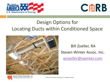
Finite Element MethodNewton Method MeshTemperature DistributionHeat Flux Magnitude22Table 1. Effective R-values of RSI -1.4 (RUS-8.0) Ducts by Insulation Strategy, m -K/W (hr-ft - F/Btu)DuctDiameter,mm (in)100 (4)150 (6)200 (8)250 (10)300 (12)350 (14)400 )(6.7)(7.2)(7.5)(7.7)(7.9)(8.0)Encapsulatedwith 38 mm(1.5 in) of ccSPFPartially1.74 (9.9)2.04 (11.6)2.24 (12.7)2.40 (13.6)2.51 (14.3)2.61 (14.8)2.68 (15.2)1.5 (8.8)1.9 (10.9)2.2 (12.6)2.5 (14.2)2.7 (15.5)2.9 (16.7)3.1 (17.8)Buried (Not .76.26.6(17.9)(22.6)(26.4)(29.6)(32.5)(35.0)(37.4) 2012 Steven Winter Associates, Inc. All rights reserved.Buried & Encapsulated with 38mm (1.5 in) of 4)(44.7)(47.7)
Install Low-Profile, Compact Duct Design Before ceiling drywall After ceiling drywall 2012 Steven Winter Associates, Inc. All rights reserved.
Apply 1.5” minimum ccSPF Apply min. 1.5” ccSPF prior to or after ceiling gypsum board 2012 Steven Winter Associates, Inc. All rights reserved.
Install Loose-fill insulation Insulation must be ASTM classified as “mineral-fiber”, and mustcover the ccSPF by a minimum of 1.5” (cellulose doesn’t qualify)Some foams are exempt from this requirement (more in a moment) 2012 Steven Winter Associates, Inc. All rights reserved.
Option: Buried / Encapsulated DuctsAdvantages and Limitations Low-cost in simple plansEasy to execute w/ nochanges to enclosureMinimal plan coordinationFlexible register location2009 IRC compliantSections R316.5.3, M1601.3 Requires HVAC designcoordinationNo provision for AHU 2012 Steven Winter Associates, Inc. All rights reserved.
Contact InfoSteven Winter Associates, Inc.61 Washington St.Norwalk, CT 06854203-857-0200Bill Zoellerwzoeller@swinter.com 2012 Steven Winter Associates, Inc. All rights reserved.
Duct Diameter, mm (in) Insulated Round Encapsulated with 38 mm (1.5 in) of ccSPF Buried (Not Encapsulated) Buried & Encapsulated with 38 mm (1.5 in) of ccSPF Partially Fully Deeply 100 (4) 1.05 (6.0) 1.74 (9.9) 1.5 (8.8) 2.1 (12.0) 3.2 (17.9) 2.5 (14.4) 3.1 (17.5) 4.0 (22.7) 150 (6) 1.18 (6.7) 2.04 (11.6) 1.9 (10.9) 2.6 (14.9) 4.0 (22.6) 3.2 .