Transcription
GFA-555seOWNER’S MANUALHigh-Current Power Amplifier
Congratulations on your purchase of the Adcom GFA-555seYou have made a wise choice that will reward you with exceptionally accurate musical sound reproduction foryears to come. To realize the full potential of your new amplifier, please read these operating and installationinstructions thoroughly before attempting to make any connections to it.The GFA-555se is not only designed to reproduce the highest quality sound but also to deliver the greatestpossible value. It is our engineers’ passion for perfection that has enabled our components to be judged theequivalent of others costing two, three, or even five times as much. Our engineering team consistently strivesto develop and design products that will exceed your expectations. Our goal at Adcom is to let more consumers hear high-end quality sound without paying high-end prices.All Adcom components are the result of a long-standing dedication to innovation, quality, simplicity, and value.Adcom: We have the power — and now, so do you!AVERTISSEMENTDANGER D’ÉLECTROCUTIONNE PAS OUVRIRWARNING: TO REDUCE THE RISK OF ELECTRIC SHOCK,DO NOT REMOVE COVER (OR BACK);NO USER-SERVICEABLE PARTS INSIDE;,REFER SERVICING TO QUALIFIED SERVICE PERSONNEL.AVERTISSEMENT:POUR ÉLIMINER TOUT RISQUED’ÉLECTROCUTION, NE PAS OUVRIR LE COUVERCLE (OULA PARTIE ARRIÈRE). AUCUNE PIECE RÉPARABLE PARL’UTILISATEUR NE SE TROUVE À L’INTÉRIEUR. POURTOUTE INTERVENTION D’ENTRETIEN OU DE RÉPARATIONSE CONFIER AUX TECHNICIENS QUALIFIÉS.The lightning flash with arrowhead symbol, within an equilateral triangle, is intended to alert the user to the presenceof uninsulated “dangerous voltage” withinthe product’s enclosure that may be ofsufficient magnitude to constitute a riskof electric shock.La flèche symbolisant l’éclair dans untriangle équilateral a pour objet de tirerl’attention de l’utilisateur sur le fait, qu’il y a des “tensions dangereuses” nonisolées à l’intérieurde l’enceinte duproduit qui peuvent être suffisammentimportantes pour conduire au risqued’électrocution.The exclamation point within an equilateral triangle is intended to alert the userto the presence of important operatingand maintenance (servicing) instructionsin the literature accompanying the appliance.Le point d’exclamation au sein d’un triangle équilateral a pour objet de tirerl’attention de l’utilisateur sur le fait qu’il y a des instructions de mise en service et d’entretien (de réparation) dansles fiches descriptives de l’appareil quidoivent obligatoirement être respectées.Do not place this unit on an unstablecart, stand, tripod, bracket, or table. Theunit may fall, causing serious injury to achild or adult, and serious damage to theunit. Use only with a cart, stand, tripod,bracket, or table recommended by themanufacturer or sold with the unit. Anymounting of the device should follow themanufacturer’s instructions, and shoulduse a mounting accessory recommendedby the manufacturer.2
TABLE OF CONTENTSLETTER FROM THE ADCOM TEAM. . . . . . . . . . . . . . . . . 2SAFETY INFORMATION . 4DESCRIPTION OF UNITGFA-555se FEATURES . 5WARRANTY INFORMATION . 5INSTALLATION & HOOKUPUNPACKING THE GFA-555se . .6INSTALLING THE GFA-555se . .6CONNECTING THE GFA-555se . .7STEREO/BRIDGED MONO INPUT/OUTPUT.7-8OPERATIONFRONT AND REAR PANEL DIAGRAMS . .9DESCRIPTION OF UNIT: REAR PANEL . .10-11DESCRIPTION OF UNIT: FRONT PANEL . 11-12TROUBLESHOOTINGRESOLVING PROBLEMS . . 13CARING FOR YOUR GFA-555se . . 14SERVICE INFORMATION . 14GFA-555se SPECIFICATIONS . 15-16
THE FOLLOWING PRECAUTIONS AND SAFETY INSTRUCTIONSARE REQUIREMENTS OF ETL AND ETLC SAFETY REGULATIONS THERE ARE NO USER SERVICEABLE PARTS IN THIS PRODUCT.DO NOT ATTEMPT SERVICING OF THIS UNIT YOURSELF. REFERSERVICING TO QUALIFIED SERVICE PERSONNEL.Read all the safety and operating instructions before connecting or using this unit.Retain this notice and the owner’s manual for future reference.All warnings on the unit and in its operating instructionsshould be adhered to.All operating and use instructions should be followed.Do not use this unit near water. For example, near a bathtub,washbowl, kitchen sink, laundry tub, in a wet basement, ornear a swimming pool.The unit should be installed so that its location or positiondoes not interfere with its proper ventilation. For example,it should not be situated on a bed, sofa, rug, or similar surface that may block the ventilation openings; or placed in abuilt-in installation, such as bookcase or cabinet, that mayimpede the flow of air through its ventilation openings.The unit should be situated away from heat sources such asradiators, heat registers, stoves, or other devices (includingamplifiers) that produce heat.The unit should be connected to a power supply outlet onlyof the voltage and frequency marked on its rear panel.This Class I apparatus shall be connected to a MAINS socketoutlet with a protective earthing connection.As the plug is used as the disconnect device, the disconnectdevice shall remain readily operable.The power supply cord should be routed so that it is notlikely to be walked on or pinched, especially near the plug,convenience receptacles, or where the cord exits from theunit.Clean unit only as recommended in its instruction manual.The power supply cord of the unit should be unplugged fromthe wall outlet when it is to be unused for a long period oftime and during electrical storms.Care should be taken so that objects do not fall, and liquidsare not spilled, into the enclosure through any openings.This unit should be serviced by qualified service personnelwhen:a. The power cord or the plug has been damaged; orb. Objects have fallen, or liquid has been spilled, into theunit; orc. The unit has been exposed to rain, or liquids of anykind; ord. The unit does not appear to operate normally, or exhibits a marked change in performance; ore. The device has been dropped, or the enclosure damaged.CAUTION POWER LINESAny outdoor antenna must be located away from all power lines.OUTDOOR ANTENNA GROUNDINGIf an outside antenna is connected to your tuner or tuner/preamplifier, be sure the antenna system is grounded so as to provide some protection against voltage surges and built-up staticcharges. Section 810 of the National Electrical Code, ANSI/NFPANo. 701984, provides information with respect to proper grounding of the mast and supporting structure, grounding of the lead-inwire to an antenna discharge unit, size of grounding conductors,location of antenna discharge unit, connection to grounding electrodes, and requirements for the grounding electrode.a.b.c.d.Use No.10 AWG (5.3 mm2) copper, No.8 AWG (8.4 mm2) aluminum, No.17 AWG (1.0 mm2) copper clad steel or bronzewire, or larger, as a ground wire.Secure antenna lead-in and ground wires to house withstand-off insulators spaced from 46 feet (1.221.83 m) apart.Mount antenna discharge unit as close as possible to wherelead-in enters house.Use jumper wire not smaller than No.6 AWG (13.3 mm2) copper, or the equivalent, when a separate antenna groundingelectrode is used. See NEC Section 810-21 (j).EXAMPLE OF ANTENNA GROUNDING AS PER NATIONAL ELECTRICAL CODE INSTRUCTIONS CONTAINED IN ARTICLE 810. RADIO AND TELEVISION EQUIPMENT.WARNINGTO REDUCE THE RISK OF FIRE OR ELECTRIC SHOCK, DO NOTEXPOSE THIS UNIT TO RAIN OR MOISTURE.AVERTISSEMENTAFIN D’ÉVITER TOUT RISQUE D’INCENDIE OU D’ÉLECTROCUTION,NE PAS EXPOSER CET APPAREIL À LA PLUIE NI À L’HUMIDITÉ.NOTE TO CATV SYSTEM INSTALLERThis reminder is provided to call the CATV system installer’s attention to Article 82022 of the National Electrical Code that provides guidelines for proper grounding and, in particular, specifiesthat the cable ground shall be connected to the grounding systemof the building, as close to the point of cable entry as practical.CAUTIONTO PREVENT ELECTRIC SHOCK DO NOT USE THIS POLARIZEDPLUG WITH AN EXTENSION CORD, RECEPTACLE OR OTHEROUTLET UNLESS THE BLADES CAN BE FULLY INSERTED TO PREVENT BLADE EXPOSURE.NOTE TO AUDIO SYSTEM INSTALLERThe GFA-555se is capable of delivering very large peaks into lowimpedances, exceeding 80 amperes per channel. Always makecertain that the amplifier is disconnected from the AC outlet forat least five minutes to ensure its filter capacitors are dischargedbefore making connections to and from the amplifier. Failure toheed this precaution may result in damage to the loudspeaker(s)and/or the amplifier which is not covered by the Warranty.ATTENTIONPOUR PRÉVENIR LES CHOCS ÉLECTRIQUES NE PAS UTILISERCETTE FICHE POLARISÉE AVEC UN PROLONGATEUR, UNE PRISEDE COURANT OU UNE AUTRE SORTIE DE COURANT, SAUF SI LESLAMES PEUVENT ÊTRE INSÉRÉES À FOND SANS EN LAISSERAUCUNE PARTIE À DÉCOUVERT.4
GFA-555se FEATURES Precision‑matched devices used throughout the signal path. 60,000 µF of power supply‑filter capacitance for greater reserve capacity. Independent power supplies for each channel. Fewer gain stages improve signal reproduction accuracy. Custom toroidal power transformer provides better regulation and greater peak current capability. Independent distortion LED for each channel. High quality, gold‑plated 5-way binding posts. High quality, gold‑plated RCA jacks. High quality, balanced XLR jacks. Large independent heatsinks for greater cooling capability of output devices. Heavy gauge, anodized aluminum front panel. Powder‑coated, baked chassis and top cover for greater durability. Cooling vents for greater efficiency and cooler operation while driving low impedance loads.ADCOM Protection Plan (USA Only)ADCOM offers the enclosed valuable Limited Warranty. Please read the details on the Warranty Card carefully tounderstand the extent of the protection offered by the Warranty, its reasonable limitations, and what you shoulddo in order to obtain its benefits. Be sure to verify that the serial number printed on the rear panel matches theserial number on the outer carton. If any number is altered or missing, or if the ADCOM Warranty Card is notincluded in the carton, you should notify us immediately in order to ensure that you have received a genuineADCOM product which has not been opened, mishandled, or tampered with in any way. Always retain youroriginal sales receipt as a proof of purchase.5
INTRODUCTIONCongratulations on your decision to purchase the GFA-555se power amplifier. By use of updated components in the classicADCOM GFA-555 design, we have reestablished our heritage of high performance and audiophile quality at the greatestpossible value. You have made a wise choice that will reward you for years to come with exceptionally accurate andmusical sound reproduction. To realize the full potential of your new amplifier, and before making any connections to it,please read these operating and installation instructions thoroughly.UNPACKING THE GFA-555seBefore your new ADCOM amplifier left our factory, it was carefully inspected for physical imperfections and tested forall electrical parameters as a routine part of ADCOM’s systematic quality control. This, along with full operational andmechanical testing, should ensure a product flawless in both appearance and performance. After you have unpacked theGFA-555se, inspect it for physical damage. Save the shipping carton and all packing material as they are intended toreduce the possibility of transportation damage, should the amplifier ever need to be shipped again. In the unlikely eventdamage has occurred, notify your dealer immediately and request the name of the carrier so a written claim to covershipping damages can be initiated. THE RIGHT TO A CLAIM AGAINST A PUBLIC CARRIER CAN BE FORFEITED IF THE CARRIERIS NOT NOTIFIED PROMPTLY IN WRITING AND IF THE SHIPPING CARTON AND PACKING MATERIALS ARE NOT AVAILABLE FORINSPECTION BY THE CARRIER. SAVE ALL PACKING MATERIALS UNTIL THE CLAIM HAS BEEN SETTLED.INSTALLING THE GFA-555seDuring normal home operation the internal heatsinks of the GFA-555se may become warm. However, there are instancesduring high‑level playback into low impedances when the heatsinks will become much warmer than usual. To ensure theamplifier’s long‑term, trouble‑free operation it is necessary to provide adequate ventilation for the heatsinks. Therefore,the GFA-555se should be kept away from external sources of heat such as radiators and hot‑air ducts. The GFA-555seshould never be placed with other heat‑producing components in a cabinet or enclosure lacking free air flow. The topand bottom panel of the amplifier’s chassis have been provided with vents to allow the necessary cooling of the internalcomponents. It is imperative that these vents are not obstructed in any way.We recommend that you do not stack other components on top of the GFA-555se. This is particularly important if yoursystem includes low‑impedance loudspeakers which are difficult to drive, or if you will consistently demand high volumelevels from the amplifier and speaker system. Not only will heat generated by the amplifier affect the performance ofequipment stacked on top of the GFA-555se, but the free flow of air through the ventilating slots in the amplifier may bepartially obstructed.If you observe these recommendations, the GFA-555se will perform reliably in any reasonable environment. You shouldalso pay attention to such normal considerations as protection from excessive dust and moisture. Occasional vacuumingof accumulated dust on the chassis, panels and around the ventilating slots should be all that is required. The optimalperformance of your new GFA-555se will ultimately depend on the care with which you make the connections betweenthe amplifier, preamplifier and the loudspeakers. All input and output signal connections should be made only with highquality, low‑loss, low capacitance cables following the recommendations in the Inputs and Outputs section of CONNECTINGTHE GFA-555se .6
CONNECTING THE GFA-555seWhen connecting the amplifier to the loudspeaker, it is vital to maintain proper polarity (positive to positive, negative tonegative). On the GFA-555se , the positive terminal is color coded RED and labeled “ ”, and the negative is color codedBLACK and labeled “-”. The positive terminal on the speaker will be color coded RED, or will be labeled “ ”, “pos”,“positive”, “8 ohms” or “4 ohms”. The negative terminal on the speaker will be color coded BLACK, or will be labeled“-”, “neg”, “negative”, “C”, “Common”, “G”, or “ground”.It is recommended that your speaker cables be terminated with “U” type spade connectors. These will give the mostcontact area insuring long‑term reliability. The spade connector should have a maximum width of 0.57 inches and anopening width of no less than 0.25”.To properly connect the speaker cable to the binding posts, turn the insulated head of the binding post clockwise untilthe wire or connector is firmly secured. Finger pressure is sufficient and you should not use pliers or other tools whichcould damage or over-tighten the binding-post assembly. The binding posts, have been designed in such a way thatfinger pressure is all that is required to cause a “pinching” action among the different metal surfaces to ensure properconnection.It is very important to use the correct size of wire in order to avoid unnecessary loss of amplifier power in the cable,reduction of amplifier damping factor and other undesirable conditions. Sound audio engineering practice suggests theuse of at least AWG16, stranded, copper cable. Recommended capacitance of the speaker wire should not exceed 5OpFper foot. This insures high frequencies will not be rolled‑off.All loudspeakers having a nominal impedance down to 4 ohms can be connected to and driven by the GFA-555se. Theamplifier can drive these low‑impedance speakers at more than adequate power levels with no difficulty. It should benoted that many loudspeaker systems which are nominally rated at 4 ohms drop in impedance, in some parts of theirfrequency range, to as low as 2 ohms (and sometimes less). You will not experience difficulties even with these very lowimpedance loads unless you demand excessively high volumes levels from your system.It is suggested to follow this chart for speaker lengths and wire gauges. If longer runs are needed, it is best to consultwith your ADCOM Dealer to maximize the performance of your system with your exact conditions.up to 24 feetAWGI6up to 36 feetAWGI4up to 58 feetAWGI2STEREO/BRIDGED MONO INPUT/OUTPUTThe GFA-555se can be used as a very powerful mono amplifier to drive 8-ohm impedance loudspeakers when in its“bridged” mode. No modification to the amplifier is necessary for operation in the bridged mode, nor are any additionalaccessories required. However, you will need two GFA-555ses for stereophonic reproduction, if you are using them inthe bridged mono mode.7
To set the amplifier in bridged mono operation, flip the STEREO/BRIDGED input switch into the BRIDGED position. Whenin the bridged mono mode, input to the amplifier is made only through the LEFT input jack. The connection to theRIGHT input jack should be removed since the right-channel input portion of the amplifier is inoperative.Only a single loudspeaker is to be connected to the GFA-555se when in the bridged mono mode. Please note thatconnections made to the loudspeaker from the GFA-555se, when used in the bridged mono mode, are different fromthose made when the amplifier is used in the stereo mode. The LEFT RED output binding-post terminal (labeled BRIDGEDMONO OUTPUT “ ”) should be connected to the loudspeaker input terminal color-coded RED (or labeled POSITIVE, “ ”,POS, 8 OHMS or 4 OHMS). The RIGHT RED output binding post terminal on the amplifier (labeled BRIDGED MONO OUTPUT“-”) should be connected to the BLACK loudspeaker terminal (or labeled NEG, “-”, C, COM, COMMON, G, or GROUND).Please note that if you want to insure correct stereo phasing with optimal bass response, you must observe theseconnections precisely.Although the GFA-555se can generate a substantially greater amount of power in the bridged mono mode than whenit is in its normal stereo mode, it requires the use of loudspeakers the nominal impedance of which does not dropbelow 4 ohms. It is not recommended that the GFA-555se be used in the bridged mono mode into loudspeakers, ormultiple loudspeaker loads, which drop in value substantially below 4 ohms. Otherwise, you may trigger the THERMALPROTECTION or blow one of the DC RAIL FUSES. A little known fact is that when any amplifier is operated in the bridgedmode, the load is “split” between the two amplifiers in the bridged configuration. Therefore, an 8-ohm loudspeaker willbe seen by the amplifier as if it were a 4-ohm load; a 4-ohm loudspeaker load will be seen by the amplifier as a 2-ohmload.NOTE:If the connections described above are followed exactly, the GFA-555se will be polarity correct, that is, it will not invert“phase”. Any positive-going signal at its input will appear as a positive-going signal at the loudspeaker.8
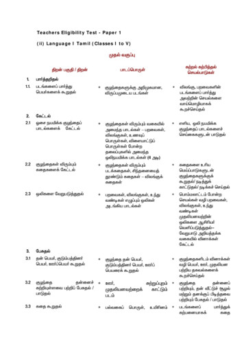
REAR PANEL(1 )(1 )(2 )(2 )(6 )(3 )(4 )(5 )FRONT PANELmodel GFA-555sepower(7 )high current power amplifierinstantaneous distortion alertRLchannel(8 )(10)(1) Inputs (unbalanced)(6) Mode Switches(2) Inputs (balanced)(7) On/Off Switch(3) Output Binding Posts(8) Power LED(4) AC Fuse(9) Thermal Protection LED(5) AC Power Cord(10) Distortion Alert LEDs9thermal protection(9 )
DESCRIPTION OF UNIT: REAR PANELREPLACE THE AC Fuse ONLY WITH AN EXACT REPLACEMENTFUSE. The proper fuse values are:(1) Inputs (unbalanced)GFA-555se for 115 volt operationFuse RatingBUSS Littelfuse 12 Amp 250 Volt . AGC-12/250V . (3AB) 314012/250VThe audio inputs for the GFA-555se are throughhigh‑quality, gold‑plated RCA jacks to minimizehigh‑frequency losses, noise, etc. They will acceptstandard RCA-type plugs, one for each channel; Left andRight. To insure that the performance designed into theamp is preserved, you should use the highest qualityaudio cables possible. There are many cables which arecolor‑coded and specifically designed for this application.Your ADCOM dealer can help select the best cable foryour needs. (See CONNECTING THE GFA-555se for moreinformation).GFA-555se for 230 volt operationFuse RatingBUSS Littelfuse 6 Amp 250 Volt . AGC-6/250V . (3AG) 314006/250VBefore attempting to replace a failed fuse, be certainto unplug the AC Power Cord from the AC wall outlet toprevent possible electrical shock. Replace the AC Fuseonly with one identical in type and rating as printed onthe rear panel. DO NOT USE ANY SUBSTITUTE FUSES WITHDIFFERENT RATINGS OR VALUES. Failure to observe this(2) Inputs (balanced)The audio inputs for the GFA-555se are throughhigh‑quality, Balanced XLR jacks to minimizehigh‑frequency losses, noise, etc. They will acceptstandard XLR-type plugs, one for each channel; Left andRight. To insure that the performance designed into theamp is preserved, you should use the highest qualityaudio cables possible. There are many cables specificallydesigned for this application. Your ADCOM dealer can helpselect the best cable for your needs. (See CONNECTINGTHE GFA-555se for more information).precaution may cause serious damage to the amplifiercircuits, may create a hazard fire, and may void the warranty.If the Power LED (8) does not glow, it may be an indicationthat the AC fuse has blown. If you are not sure, or theamplifier displays other symptoms, please consult theRESOLVING PROBLEMS section on page 12.Fuse replacementTo remove the fuse‑holder cap, you will need a #2 standardPhillips screwdriver. Place the screwdriver in the recessed“crosshead” in the cap. Turn the cap counter‑clockwise,until the cap releases out towards you. Grasp the cap withyour fingers and pull it completely out. The fuse is insertedin the back of the cap; gently pull it free.(3) OutputsThe GFA-555se connections to the loudspeakers are madethrough high‑grade, 5-way, gold‑plated binding postterminals. There are two terminals for each speaker,which are colored RED for the positive ( ) output andBLACK for the negative (‑) output.The binding posts will accept a variety of connector types;the most secure and prevalent of these is the “U”-typespade connectors (at least 0.25’’ wide and maximum widthof 0.57”),. The terminal will also accept bare wire (upto AWG1O) and “banana” type plugs (single or dual). (SeeCONNECTING THE GFA-555se for more information).Since the fuse has a ceramic body, you cannot visuallyexamine the fuse element, it is therefore suggested thatyou replace it with an identical substitute or bring the fuseto your ADCOM dealer so they may check its integrity. Toreplace the fuse, insert it in the back of the fuse‑holdercap. Place the cap into the fuse‑holder. Place thescrewdriver in the recessed slot, gently press in and turn1/8-turn clockwise.(5) AC Power Cord(4) AC FuseThe AC Fuse protects the electronic circuits of the GFA555se. This fuse, normally, will fail only if there is anoverload within the GFA-555se. It may, however, fail if theamplifier attempts to deliver very high power into verylow‑impedance loudspeakers. In either case, BE SURE TO10The AC cord provides power to operate all the GFA-555se’scircuits. Its plug can be connected to a standard walloutlet provided the outlet supplies a voltage compatiblewith the power requirements printed on the rear panel ofthe GFA-555se.
(6) Mode SwitchesFor normal stereophonic mode of operation, theSTEREO/BRIDGED input switch should be set to STEREO.Otherwise, the amplifier will operate in the bridgedmono input mode by which you will amplify only theleft channel through both outputs of the amplifier. TheBALANCED/UNBALANCED selector switches should be setto accommodate the type of input connectors that youare using. The upper connectors (RCA-jacks) are used forunbalanced input signals and the lower connectors (XLRjacks) are used for balanced input signals.automatically and normal operation will resume. If youare to avoid tripping the thermostat in the transformercontinually, you must reduce the sound level demands,correct the load impedance of the loudspeakers, or both.(9) Thermal Protection LED(8) Power LEDThe GFA-555se is provided with a thermal protectioncircuit which will shut down the amplifier if its heatsinktemperature reaches 75 C. The Thermal Protection LEDwill light whenever the thermal protection circuit has beentriggered and the amplifier is inoperative. The thermalprotection circuitry will typically be triggered by veryhigh power demands into impedances much lower thanthe amplifier is capable of driving at those levels. If anyamplifier channel’s output through the loudspeaker(s)ceases abruptly, and its Thermal Protection LED glows,you will know that its heatsink temperature has becomeunacceptably high and the circuitry is protecting theamplification devices. Please note that the Power LED (8)will remain on and the amplifier will still be energized.Once the temperature of the heatsink(s) drops to a safeoperating level, that amplifier will automatically resumeoperation.This LED will glow whenever the On/Off Switch (7) isturned on and the GFA-555se is energized. The PowerLED indicates that there is AC voltage being fed to theamplifier, but it does not signify that all the amplifier’scircuits are in operation. If, for example, the ThermalProtection LED (9) glows, that amplifier will not producesound even though the Power LED may still glow. Whenthe GFA-555se is turned off, the Power LED will take sometime to fade out completely. It may take up to 30 secondsto fully extinguish.Activation of the Thermal Protection circuitry in anyof the amplifiers in the GFA-555se is an indication thatthe amplifier has been over driven or that the loadthe loudspeakers are presenting to the amplifier isunreasonably low. If you wish to prevent recurrentactivation of the thermal protection circuitry, you mustreduce the volume‑level demands or correct the loadimpedance condition which may be causing activation ofthis circuitry.DESCRIPTION OF UNIT: FRONT PANEL(7) On/Off SwitchThe On/Off Switch controls power to the powertransformer and circuits of the GFA-555se. Whenever theGFA-555se is energized the Power LED (8) will glow red. Toturn the GFA-555se on, press the button up. It will remainin the “engaged” position while the unit is energized. Toturn the GFA-555se off, press the button down and it willmove to the “disengaged” position.Additionally, the internal power transformer is providedwith a thermostat which will interrupt power into thetransformer if its temperature exceeds 125 C. This hightemperature will seldom, if ever, be encountered unlessthe amplifier is subjected to abnormal conditions, suchas operation into loads of less than 3 ohms at very highlistening levels, etc. If the AC Fuse (4) has not failed, thePower LED (8) is out, and the Thermal Protection LED (9)does not glow, this would indicate that the thermostatwithin the transformer has opened.Once the temperature within the transformer decreasesto a normal level, the thermostat will reset itself(10) Distortion Alert LEDsThe Distortion Alert circuit is a unique ADCOM distortiondetection system which reads all forms of non‑lineardistortion such as THD, IM, slew‑induced, “clipping”, etc.The Distortion Alert LEDs will light when distortion reachesapproximately 1% regardless of impedance, voltage/current phase angle or the reactance of the loudspeakerswhich the amplifier is driving. Sometimes, when theamplifier is in use, the LEDs may occasionally flickerduring high volume listening, particularly if you are drivinglow impedances. This flickering is no cause for concern.The LEDs are simply warning you that the amplifier isapproaching its maximum power output into the particular11
loudspeakers you are using. If, however, the DistortionAlert LEDs glow brightly or are illuminated most of thetime during playback, you are over driving the amplifierand should turn down your volume control to reducethe listening level, otherwise it may cause the ThermalProtection to be activated or, in extreme cases, damageyour loudspeakers.WARNINGWHENEVER CONNECTIONS TO OR FROM THE GFA555SE ARE BEING MADE, BE CERTAIN THAT THEAC ON/OFF SWITCH OF THE AMPLIFIER IS IN THEOFF POSITION, THE AC CORD OF THE AMPLIFIER ISDISCONNECTED FROM THE AC WALL OUTLET ANDTHAT ALL ASSOCIATED COMPONENTS ARE OFF.12
RESOLVING PROBLEMSUse the chart below to solve common situations that don’t require professional attention. If the steps stated inPOSSIBLE SOLUTION do not resolve your problem, then please contact your ADCOM Dealer or call the ADCOM CustomerService Department. Any problems not covered here should be brought to the attention of your ADCOM Dealer or ADCOMCustomer Service Department.SYMPTOMPOSSIBLE REASONPOSSIBLE SOLUTIONPower LED does notglow.AC Power Cord(s) not plugged in.Power switch not (pressed) on.Plug in AC Power Cord(s).Press the Power switch.No sound.AC Fuse(s) failed.Transformer thermal protection engaged.Preamp or source unit is not on.Connections in rear of amp are loose.INPUT(s) or OUTPUT(s) connectordisconnected or loose.Replace AC Fuse(s).Wait until unit cools down. It will reset.Make sure whole system is on.Verify all connections on rear of amp.Verify both connections on that channel.Speaker disconnected.Internal protection engaged.Verify connection at speaker.Bring to Dealer or Service Center.Ground loop (difference in ground voltagesbetween components).Problem with source unit (CD, tape, etc.),or RCA cable connecting that source unitto the preamp.Some major appliance, dimmer, halogen orfluorescent light is creating interference.If Cable TV is present (see Note 1).If Cable TV is not present (see Note 2).Try different source (tuner, tape, etc.)and/or different RCA cable.Power LED glows,but no
ADCOM offers the enclosed valuable Limited Warranty. Please read the details on the Warranty Card carefully to understand the extent of the protection offered by the Warranty, its reasonable limitations, and what you should do in order to obtain its benefits. Be sure to verify that the serial number printed on the rear panel matches the