Transcription
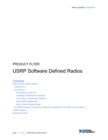
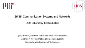
USRP User’s and Developer’s GuideMatt Ettus, Ettus Research LLC matt@ettus.com This guide explains both basic usage of the USRP as well as how to expand it.Table of ContentsIntroduction . . . . . . . . . . . . . . . . . . . . . . . . . . . . . . . . . . . . . . . . . . . . . . . . . . . . . . . . . . . . . . . . . . . . . . . . . . . . . . . . . . . . . .System Requirements . . . . . . . . . . . . . . . . . . . . . . . . . . . . . . . . . . . . . . . . . . . . . . . . . . . . . . . . . . . . . . . . . . . . . . . .Capabilities . . . . . . . . . . . . . . . . . . . . . . . . . . . . . . . . . . . . . . . . . . . . . . . . . . . . . . . . . . . . . . . . . . . . . . . . . . . . . . . . .Getting Started . . . . . . . . . . . . . . . . . . . . . . . . . . . . . . . . . . . . . . . . . . . . . . . . . . . . . . . . . . . . . . . . . . . . . . . . . . . . . . . . . . .Getting all the Software . . . . . . . . . . . . . . . . . . . . . . . . . . . . . . . . . . . . . . . . . . . . . . . . . . . . . . . . . . . . . . . . . . . . . .Using your USRP . . . . . . . . . . . . . . . . . . . . . . . . . . . . . . . . . . . . . . . . . . . . . . . . . . . . . . . . . . . . . . . . . . . . . . . . . . .FPGA . . . . . . . . . . . . . . . . . . . . . . . . . . . . . . . . . . . . . . . . . . . . . . . . . . . . . . . . . . . . . . . . . . . . . . . . . . . . . . . . . . . . . . . . . . .Standard FPGA Configuration . . . . . . . . . . . . . . . . . . . . . . . . . . . . . . . . . . . . . . . . . . . . . . . . . . . . . . . . . . . . . . . .Daughterboard Interface . . . . . . . . . . . . . . . . . . . . . . . . . . . . . . . . . . . . . . . . . . . . . . . . . . . . . . . . . . . . . . . . . . . . . . . . . . .Power . . . . . . . . . . . . . . . . . . . . . . . . . . . . . . . . . . . . . . . . . . . . . . . . . . . . . . . . . . . . . . . . . . . . . . . . . . . . . . . . . . . . . .Logical Interface . . . . . . . . . . . . . . . . . . . . . . . . . . . . . . . . . . . . . . . . . . . . . . . . . . . . . . . . . . . . . . . . . . . . . . . . . . . .Analog Interface . . . . . . . . . . . . . . . . . . . . . . . . . . . . . . . . . . . . . . . . . . . . . . . . . . . . . . . . . . . . . . . . . . . . . . . . . . . .Digital Interface . . . . . . . . . . . . . . . . . . . . . . . . . . . . . . . . . . . . . . . . . . . . . . . . . . . . . . . . . . . . . . . . . . . . . . . . . . . . .Connector Pinouts . . . . . . . . . . . . . . . . . . . . . . . . . . . . . . . . . . . . . . . . . . . . . . . . . . . . . . . . . . . . . . . . . . . . . . . . . . .Available Daughterboards . . . . . . . . . . . . . . . . . . . . . . . . . . . . . . . . . . . . . . . . . . . . . . . . . . . . . . . . . . . . . . . . . . . . . . . . . .BasicRX . . . . . . . . . . . . . . . . . . . . . . . . . . . . . . . . . . . . . . . . . . . . . . . . . . . . . . . . . . . . . . . . . . . . . . . . . . . . . . . . . . .BasicTX . . . . . . . . . . . . . . . . . . . . . . . . . . . . . . . . . . . . . . . . . . . . . . . . . . . . . . . . . . . . . . . . . . . . . . . . . . . . . . . . . . . .14455666777888899IntroductionThe Universal Software Radio Peripheral, or USRP (pronounced "usurp") is designed to allow general purposecomputers to function as high bandwidth software radios. In essence, it serves as a digital baseband and IF section ofa radio communication system. In addition, it has a well-defined electrical and mechanical interface to RF front-ends(daughterboards) which can translate between that IF or baseband and the RF bands of interestThe basic design philosophy behind the USRP has been to do all of the waveform-specific processing, like modulation and demodulation, on the host CPU. All of the high-speed general purpose operations like digital up- anddownconversion, decimation and interpolation are done on the FPGA.It is anticipated that the majority of USRP users will never need to use anything other than the standard FPGAconfiguration. However, for those users that wish to, the FPGA design may be changed or replaced. All of theinterfaces are well defined and documented.Figure 1. USRP with Daughterboards1
USRPUser’s and Developer’s Guide2
USRPUser’s and Developer’s Guide3
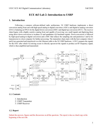
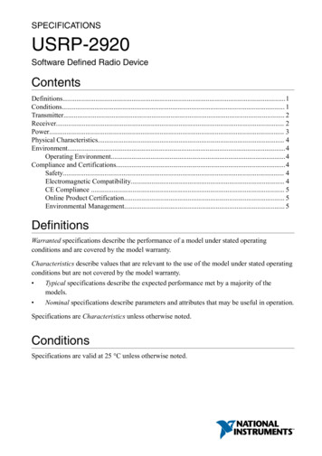
USRPUser’s and Developer’s GuideThis USRP has 2 BasicTX and 2 BasicRX boards mounted on it. Notice that the boards on the left are rotated 180degrees.System RequirementsThe USRP requires a PC or Mac with a USB2 interface.CapabilitiesThe USRP has 4 high-speed analog to digital converters (ADCs), each at 12 bits per sample, 64 million samples persecond. There are also 4 high-speed digital to analog converters (DACs), each at 14 bits per sample, 128 millionsamples per second. These 4 input and 4 output channels are connected to an Altera Cyclone EP1C12 FPGA. TheFPGA, in turn, connects to a USB2 interface chip, the Cypress FX2, and on to the computer. The USRP connects tothe computer via a high speed USB2 interface only, and will not work with USB1.1.Figure 2. Universal Software Radio Peripheral4
USRPUser’s and Developer’s GuideGetting StartedGetting all the SoftwareThe first step in using your USRP system is to get all of GNU Radio installed. This can sometimes be a dauntingprocess, as there are several other libraries which will need to be installed first.Library Dependencies SWIGWe use SWIG (Simple Wrapper Interface Generator) to tie together the C and Python code in the GNU Radiosystem. We require that you have version 1.3.24 or newer. You’ll probably have to compile it from source, whichyou can find here: SWIG [http://www.swig.org] FFTWFFTW is the library which GNU Radio uses for FFTs. GNU Radio requires version 3.0.1 or newer, and it mustbe compiled for single precision. You can get it from the FFTW Homepage [http://www.fftw.org] Boost LibraryBoost provides several low-level structures used in our C code. If it is not included in your OS distribution,you can get it here: Boost [http://boost.org] CPP UnitCPPUnit provides our unit-testing framework. This creates automated tests to insure that code does not breakwhen changes are made. Get it at the CPP Unit Homepage [http://cppunit.sf.net]Getting GNU Radio and the USRP codeThere are several packages of software which make up GNU Radio and the USRP support software. Links to the latestversions of each can be found on the GNU Radio Wiki at Download Links [http://comsec.com/wiki?GnuRadio2.X].Gr-build can greatly simplify the installation process, and its use it highly recommended.Following CVS DevelopmentDevelopment for the USRP proceeds very quickly at times, so some users may want to keep up with the latest byfollowing the CVS trees. There are three separate software repositories which contain various parts of the USRPsystem. USRP-HW, containing the hardware and FPGA designs.All of the schematics in this repository were created in gEDA [http://www.geda.seul.org]. The board layoutswere created in PCB [http://pcb.sf.net]. Verilog designs are compiled in Quartus II Web Edition from Altera[http://www.altera.com]. USRP-SW [https://sourceforge.net/cvs/?group id 22397], USRP-SW, containing firmware and host drivers forthe USRPHost side drivers and firmware which runs in the USB2 interface chip on the board.5
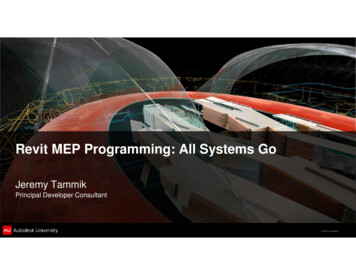
USRPUser’s and Developer’s Guide GNU Radio/gr-usrp [http://comsec.com/wiki?CvsAccess] which contains the GNU Radio interface to the USRPUsing your USRPMechanical ConnectionThe USRP ships with a complete set of standoffs, nuts and bolts. There are 20 standoffs, M3x10mm M-F, of which 4are intended to be used as "feet" for the USRP. Place them in the 4 corner holes on the main board, inserting the malepart from below. The remaining 16 are used to hold the daughterboards in place. Four of them should be connectedto the male portion of the 4 standoffs already inserted from below. The remaining 12 should be connected to theboard with the 12 M3x6mm screws from below. At this point there should be 16 standoffs on the board with the maleends up to serve as a guide for the daughterboards. The 16 M3 nuts are used to fasten the daughterboards down to themain board.The USRP accomodates 2 TX and 2 RX daughterboards. The placement of the standoffs is designed to prevent theaccidental incorrect connection of daughterboards. The 2 sides of the USRP have their daughterboard slots rotated180 degrees. The USRP should not be operated without standoffs, and daughterboards should never be connected orremoved while power is applied.Electrical ConnectionsThe USRP is powered by a 6V 4A power converter included in the kit. The converter is capable of 90-260 Vac, 50/60Hz operation, and so should work in any country. If there is a need to use another power supply, the connector is astandard 2.1mm/5.5mm DC power connector. The USRP itself only needs 5V at 2A, but a 6V supply was chosen toaccomodate future daughterboards. Extra power supplies are available from Ettus Research.The included USB cable should be connected to a USB2-capable socket on a computer. The USRP does not supportUSB 1.1 operation at this time.TroubleshootingWhen first powered up, an LED on the USRP should be flashing at about 3-4x per second. This indicates that theprocessor is running, and has put the device in a low power mode. Once firmware has been downloaded to the USRP,the LED will blink at a slower rate. If there is no blinking LED, check all power connections, and check for continuityin the power fuse (F501, near the power connector). If the fuse needs replacement, it is size 0603, 3 amps.FPGAStandard FPGA ConfigurationIn the standard fpga configuration, usrp std, all samples sent over the USB interface are in 16-bit signed integers inIQ format. When there are multiple channels (up to 4), the channels are interleaved. For example, with 4 channels,the sequence would be I0 Q0 I1 Q1 I2 Q2 I3 Q3 I0 Q0, etc.The USRP can operate in full duplex mode. When in this mode, the transmit and receive sides are completelyindependent of one another. The only consideration is that the combined data rate over the bus must be 32 Megabytesper second or less. The multiple RX channels (1,2, or 4) must all be the same data rate (i.e. same decimation ratio).The same applies to the 1,2, or TX channels, which each must be at the same data rate (which may be different fromthe RX rate).On the RX side, each of the 4 ADCs can be routed to either of I or the Q input of any of the 4 downconverters. Thisallows for having multiple channels selected out of the same ADC sample stream.6
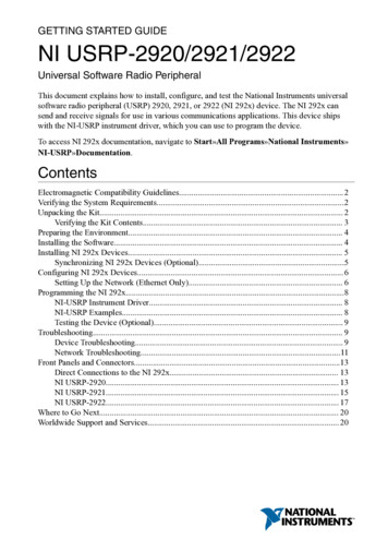
USRPUser’s and Developer’s GuideThe digital upconverters (DUCs) on the transmit side are actually contained in the AD9862 CODEC chips, not in theFPGA. The only transmit signal processing blocks in the FPGA are the interpolators. The interpolator outputs can berouted to any of the 4 CODEC inputs.Figure 3. Digital Down Converter Block DiagramDaughterboard InterfacePowerDaughterboards are provided with clean regulated 3.3V for the analog and digital sections. Additionally there is a 6Vconnection straight from the wall supply which is intended to supply a 5V LDO regulator. All daughterboards maydraw a combined total of 1.5 A.Logical Interface7
USRPUser’s and Developer’s GuideThere are slots for 2 TX daughterboards, labeled TXA and TXB, and 2 corresponding RX daughterboards, RXA andRXB. Each daughterboard slot has access to 2 of the 4 high-speed data converter analog signals (DAC outputs for TX,ADC inputs for RX). This allows each daughterboard which uses real (not IQ) sampling to have 2 independent RFsections, and 2 antennas (4 total for the system). If IQ sampling is used, each board can support a single RF section,for a total of 2 for the whole system.No antialias or reconstruction filtering is provided on the USRP motherboard. This allows for maximum flexibilityin frequency planning for the daughterboards. The analog input bandwidth of the ADCs is over 200 MHz, so IFfrequencies up to that high may be chosen. If several decibels of loss is tolerable, and IF frequency as high as 500MHz can be used.Every daughterboard has an I2C EEPROM (24LC024 or 24LC025) onboard which identifies the board to the system.This allows the host software to automatically set up the system properly based on the installed daughterboard. TheEEPROM may also store calibration values like DC offsets or IQ imbalances. If this EEPROM is not programmed, awarning message is printed every time USRP software is run.Analog InterfaceEach RX daughterboard has 2 differential analog inputs (VINP A/VINN A and VINP B/VINN B) which aresampled at a rate of 64 MS/s. The input impedance is approximately 1Kohm. The motherboard has a softwarecontrollable programmable gain amplifier on these inputs, with 0 to 20 dB of gain. With gain set to zero, full scaleinputs are 2 Volts peak-to-peak differential. When set to 20 dB, only .2 V pk-pk differential is needed to reach fullscale.If signals are AC-coupled, there is no need to provide DC bias as long as the internal buffer is turned on. It willprovide an approximately 2V bias. If signals are DC-couple, a DC bias of Vdd/2 (1.65V) should be provided to boththe positive and negative inputs, and the internal buffer should be turned off. VREF provides a clean 1 V reference.Each TX daughterboard has a pair of differential analog outputs which are updated at 128 MS/s.The signals(IOUTP A/IOUTN A and IOUTP B/IOUTN B) are current-output, each varying between 0 and 20 mA. Sincethey are high-impedance, they can be converted into differential voltages with a resistor.In addition to the high-speed signals, each daughterboard has exclusive access to 2 low-speed ADC inputs (labeledAUX ADC A and AUX ADC B) which can be read from software. These are useful for sensing RSSI signal levels,temperatures, bias levels, etc. Additionally, each board has shared access to 4 low-speed DAC signals, labeledAUX DAC A through AUX DAC D. RXA and TXA share one set of these 4 lines, and RXB and TXB sharetheir own independent set. These signals are useful for controlling gain of variable-gain amplifiers, for example.AUX ADC REF provides a reference level for gain setting if it is necessary.Digital InterfaceConnector PinoutsTable 1. RX DBoard ConnectorPin #1c1d1Namepowerc4d4DescriptionThis is powerd58
USRPUser’s and Developer’s GuideAvailable DaughterboardsBasicRXBasicTX9
The Universal Software Radio Peripheral, or USRP (pronounced "usurp") is designed to allow general purpose computers to function as high bandwidth software radios. In essence, it serves as a digital baseband and IF section of a radio communication system. In addition, it has a well-defined electrical and mechanical interface to RF front-ends