Transcription
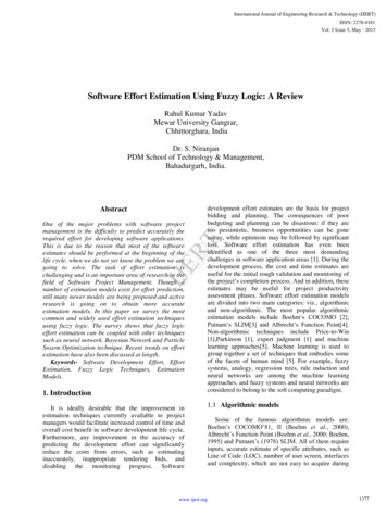
Paper ID# 901257 .PDFDELAYED DECISION FEED-BACK SEQUENCE ESTIMATION OFDMEQUALIZATION WITH CHANNEL PREDICTIONLunHuangHo P. DamG. E. Atkin, senior member, IEEEIllinois Institute of TechnologyElectrical and Computer Engineering DepartmentChicago, IllinoisABSTRACTThis paper proposes a low-complexity equalizerfor orthogonal frequency division multiplexing (OFDM)systems under time-varying frequency-selective fadingenvironments. The equalization uses suboptimummaximum likelihood sequence estimation (MLSE) incooperation with semi-blind linear prediction (SBLP) inthe estimation of the channel frequency responses. Whenthe number of pilot subcarriers is far less than the totalsubcarrier numbers, it reduces the Mean Square Error inthe channel estimation compared to conventional linearinterpolation and LMMSE (Linear Minimum Mean SquareError) algorithms. Furthermore, it doesn't require theknowledge of the statistics of the channel, which isnecessary in LMMSE. In practical application, theseparameters cannot be easily obtained and small estimationerrors cause significant performance degradation.Theoretic analysis and simulation results demonstrate thatthe proposed equalizer can effectively increase theperformance of OFDM receivers in time-varying fadingchannel.I. ng(OFDM) is a special case of multicarrier modulation withequally spaced subcarriers and overlapping spectra. Thesubcarrier interval is chosen such that mutualorthogonality is ensured. Several advantages over singlecarrier scheme have contributed significantly to increasethe popularity of OFDM in many wireless and wire-lineapplications. Consider the baseband time-domain signalgenerated by a generic OFDM system expressed as1N-lx(n) L X(k)ei2nnk/N n 0,1,., N -I(1)",N k OX(k), k 0, I,., N -I denotes the frequency-Wheredomain sequence of the modulated symbols, x(n) is thecorresponding time-domain sequence.978-1-4244-5239-2/09/ 26.00 2009 IEEEWhen the channel is time-invariant, OFDM systemsperform well. In this case, preamble symbols are used toestimate the channel frequency response, which is thenused in equalizing the subsequent OFDM symbols in thepacket.However, in time-varying frequency-selectivefading channel, the channel frequency response changesPilot SubcarriersFigure I. Subcarriers distribution patternfrom one symbol to another [1], and pilot subcarriersshould be used to update channel estimations. The mostcommonly used channel estimation method is linearinterpolation [2] [3].As shown in Figure I, assuming that the pilotsubcarriers are evenly distributed over the wholebandwidth and the number of subcarriers between twoadjacent pilot subcarriers is L, the estimation of thechannel transfer function at the pilot subcarriers can beobtained asHN(mL) HN(mL) NN(mL), m O,I, . ·, M - l.WhereMisthenumberofpilot(2)subcarriers,HN (mL) denotes the noisy transfer function of the M pilotsubcarriers Ck ml.) , NN(mL) denotes the noise at thepilot subcarrier with frequency response HN(mL). Channelestimation over the whole N subcarriers (k 0, . ,N- I )can then be obtained by linear interpolation.Without loss of generality, if a first-order linearinterpolation is used, the linear interpolation relation is10f7
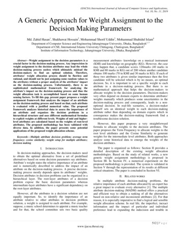
Paper ID# 901257.PDFHN(k) H N(mL i) (l-t)HN(mL) tHN(mL L) [(1- )HN(mL) [(1- }NN(mL) practical applications, these parameters cannot be easilyobtained. Furthermore, they might cause significantdegradation when the statistics of the channel change.HN(mL L)] oNN(mL L)]i 1,2,.,L -I(3)Where HN(k) is the value of the transfer function for the k mL i subcarrier, which is between those twoneighboring pilot subcarriers with transfer functionHN(mL) and HN(mL L). Since other pilot subcarriers arelocated significantly further away from these interpolatedsubcarriers than two neighboring pilot subcarriers, theperformance mainly depends on those two neighboringpilot subcarriers. The term in the first square brackets in (3)is the desired estimation, provided that every segment ofthe channel transfer function between adjacent pilotsubcarriers is ramp-like. Unfortunately, this assumptiondoes not hold for most of the cases. This model mismatchforms a part of the estimation error. So, linear interpolationhas the lowest complexity at the cost of performance.Linear minimum mean square error (LMMSE) [4]provides better channel estimation. From the linearinterpolation described above, it can be observed that thefrequency responses at close neighboring subcarriers arelinearly dependent. Therefore, it is possible to interpolatethe channel frequency response based on the correlationcoefficients among those subcarriers, instead of those fixedcoefficients dependent on subcarrier index k in linearinterpolation, as show in (3).According to [5] [6], the LMMSE channelestimation can be described as: H N LMMSE(k) R HHP ( R HPHP-Where R HHP B --1SNR-1) H LsFurthermore, when the number of pilot subcarriersM is far less than the total number of subcarriers N, bothlinear interpolation and LMMSE will be subject tosignificant performance degradation, because, for channelfrequency response, the linear dependency or correlationbetween pilot subcarrier and data subcarriers are verysmall, it results in inaccurate interpolation and estimation.However, the linear dependency between neighboringsubcarriers can be exploited. It is well known that thecorrelation coefficients are maximized between closestneighboring subcarriers. So, the most accurate channelprediction is given by the linear combination of channelfrequency response at the closest neighboring subcarriers.Given that the channel frequency response atsubcarrier k-l and k-2 are H(k-l) and H(k-2), the channelfrequency response value at subcarrier k can be predictedas:H(k) p(l)H(k -I) p(2)H(k - 2)Where p(l) and p(2) are the coefficients of a linearprediction filter.Based on this, a novel approach is proposed in this paper,which combines the channel prediction with DDFSEequalization by using a decision feed-back algorithm.The paper is organized as follows. In Section II, thesystem model and underlying theories are described. InSection III, performance analysis and upper-bound areprovided. In Section IV, the results of simulation are shownto compare the proposed scheme with traditional schemes.Section V includes the conclusions of the proposedalgorithm.(4)E[HH pH], R HPHP E[HpHpH], H denotes thechannel transfer function, H p denotes the channel transferfunction at the pilot subcarriers. HLS is the Least-Squareestimation of H p ; P is a constant dependent on the signalconstellation.After the channel estimation HN LMMSE(k) isobtained, it can be used directly in the frequency domainequalization to detect the symbols in the subcarriers.LMMSE algorithm requires the knowledge of thestatistics of the channel, e.g. R HHP ' R HPHP ' and SNR. InII. SYSTEM MODELThe system model for the proposed scheme isdescribed in Figure 2.The proposed DDFSE equalizer mainly consists oftwo parts: equalization and demodulation and channelprediction. The equalization and demodulation block isbased on the DDFSE, which is a sub-optimum MLSEalgorithm. By using this algorithm, the equalizer cangenerate soft outputs for the channel decoder. On the otherhand, the channel prediction module can be regarded as anintegral part of the equalizer, and it uses the decision feedback generated by the equalizer to predict the channelfrequency response in every subcarrier. So the equalizationand channel prediction work alternatively and20f7
PaperID#901257.PDFp [p(l) p(2) . p(1)]T is the fixed prediction filterAwith length 1, the estimated received signal can be writtenasY(k) X(k)·H(k)(8) l) X(k)H(k - i)p(i) W(k) N(k)( t;:Proposed DDFSE EqualizeriWhere W(k) L H(k - i)p(i) is the component derivedi J.l 2Figure 2. System Block Diagramcooperatively. These two modules will be discussed in thefollowing subsections.A. DDFSE equalization and demodulationSuppose that Y(k) is the input to the equalizer,thenY(k) H(k)X(k) N(k), k O,I,2,.,N-I(5)Where X(k) is the transmitted symbols, H(k) is the channeltransfer function, N(k) is the noise and N is the number ofsubcarriers.Given the received sequence Y(k) and channel transferfunction H(k), the MLSE algorithm estimates the sequenceX(k) that maximizes the likelihood function (y I x) (theconditional probability density function of the output ygiven the input x). Let the metric M ofX(k) beM IIY(k) - H(k)X(k)W(6)Since M is proportional to the log likelihood function log[ (y I x)], the sequence X(k) that minimizes the metricM, is the solution to the maximum likelihood sequenceestimation problem [7] [8].The rational function H(k) can be described interms of a state machine with state space S. The DDFSEalgorithm simplifies the MLSE by decomposing the statespace S into two subspace: U and V. Ifu is the reducedmemory of the channelH(k) [H(k -1),H(k -2), .,H(k [Y(k-l) , Y(k-2) ,., Y(k-!)]X(k-l) X(k-2)X(k-l)I)J(7)from the delayed decision feedback, N(k) denotes thenoise component.At time k, the state of the U subspace can be denoted asUk [X(k -1),.,X(k - )]And the state of the V subspace isV k [X(k- -I), .,X(k - l)]The DDFSE algorithm combines the structure of theViterbi algorithm and the decision feed-back detector. Asin the Viterbi algorithm, it uses a state machine descriptionof the channel H(k) to recursively estimate the best path inthe trellis while storing only one path for each state. Butsince each state of the DDFSE trellis provides only partialinformation about the full state of the channel, thealgorithm also uses the best path leading to each state tocompute the metric.Obviously, the alphabet size of X(k) and thedimension of U subspace (u here) determine the numberof states in the trellis, thus decide the computationalcomplexity. The V subspace is composed of the decidedsymbols in each path. An estimation of the partial state inthe V subspace store the 'feed-back information' extractedfrom the best path. Similar to a decision feed-back detector,these estimations are from past inputs that are greater thanthe Jl samples in the past.Note that if U S, the algorithm reduces to theViterbi algorithm, if V S, the algorithm is equivalent tothe zero-forcing decision feed-back detection. If SoftOutput Viterbi Algorithm (SOVA) is used to generate asoft-bit output in DDFSE [9] [10], it will further improvethe performance of the DDFSE algorithm.From the discussion above, it can be concludedthat the prediction of H(k) plays an important role in thewhole system. Thus, in the following section, an algorithmon computing the prediction filter coefficientsp [p(l) p(2) . . p(1)]T will be introduced.B. Decisionprediction30f7feed-back semi-blind linear channel
Paper ID# 901257.PDFThe function of this linear prediction algorithm isto obtain the prediction filter coefficientsp [p{l) p(2) . p{I)]T based on decision feed-back.Since this approach takes advantage of the channelfrequency response components obtained at the pilotsubcarriers, it is semi-blind.Assume that the prediction filter is P(z),i(9)P{z) LP{k)z-kk l"Where the 1is the length of prediction filter.The prediction filter P(z) is designed to minimize theoutput power of the prediction error. The optimumcoefficients for this criterion are given by solving theYule-Walker equations [11](10) l p (j)With 1 1 [0] 1 [-1] 1 [-(I -1)] 1 [1] 1 [0] I [-{I -2)] 1 [1 -1] 1 [1 - 2]p [p(l) p(2)- I [ I {I) I (2) .p(I)]T 2. At time k Ck 0, . ,N-I) , use (6), (8) to obtainmetric M for every state.3. Based on each survivor path, update l1{k 1) and pusing (7) and (10).4. Move on to the next time k 1 and go to step 2 torepeat the same procedure until k N-I.5. Retrace back along the final survivor path to obtain theoutput equalized symbols or bits.The procedure of updating p in step 3 involves a largeamount of computation. To reduce the computationcomplexity, a practical sub-optimum approach isdeveloped. Instead of updating the prediction filter alongeach survivor path, a fixed prediction filter is used to takeadvantage of the trellis structure of the DDFSE equalizer.Since the frequency domain range is [-1t, 1t] , theprediction with direction from -1t to 1t can be defined asforward prediction. In the same way, the backwardprediction is in direction from 1t to -1t. At every state, theequalizer finds out the best path that minimizes thesummation of the powers of the forward prediction errorand backward prediction error. This rule is similar to thatused in Burg's algorithm [12]. To serve this purpose, somechanges in the definition of the metric M are made. 1 [0] I {I)]The recursive steps of the proposed algorithm involvethe following.1. Initiate 11(0) based on channel estimation.T I {k) l1{k) 8 11* (-k)Where (.)T and (8) denote transposition and convolution,If p [p{l) p(2) .respectively. l1{k) is the channel frequency responseestimation. I [-{I-l)] 1 *[1-1] . The length of sequencel1{k) is I.These equations can be solved by using the LevinsonDurbin(LD)algorithm,whichonlyrequires12 0(1 2 ) operations. The LD Algorithm recursivelycalculates a predictor with a desired orderdetermining all predictors of order 1.1p{I)]T is the fixed predictionfilter with length I, at sub-carrier k, the forward predictionof the channel frequency response is Hf{k) , and thebackward prediction is Hb (k). The previous forward andbackward channel frequency response estimations areHr [HAk-1),fJAk-2), ,Hr (k - i)] andtr, [Hb(k 1), Hb(k 2), , Hb(k i)]byrespectively, thusjAfter obtaining the prediction filter P(z), thepredictionvalueofthechannelfrequencyresponse H{k) can be found out at every sub-carrier k,based on the U subspace and V subspace of the DDFSEequalizer. The coefficients of the prediction filter P(z) willbe updated along each survivor path using the algorithmspreviously discussed.Hf{k) LP{n)*Hf{k-n),n 1jHb{k) LP{n)*Hb{k n)(11)n 1Then the equation of the metric M can be expressed asC. Description of the algorithm and sub-optimumalgorithm40f7IIY(k)- fIr (k)X(k)1r IIY(k)- fIb (k)X(k)lr2 [IIH(k)- fIr (k)lr IIH(k)- fIb (k)1r]·IIX(k)11 [Iler 1 Ile W}IIX(k)11M 22b(12)
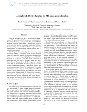
Paper ID# 901257.PDFWhere er H(k)-HAk) is the forward prediction error;and eb H(k) - Hb(k) is the backward prediction error . Themaximum likelihood solution to the equation above can beused to minimize the summation power of the forward andbackward prediction errors.used to compute branch metric M with (12). Only Hr(k) isthe new term in the updated forward channel frequencyresponse estimation. Hr (k -I) could be obtained from thepartial state estimations(decision feedback), which belongto the V subspace.For forward prediction, based on every state in thespace S: s (xk ,Xk \,.,Xk 1 \) , the updated forwardchannel frequency response estimation is[Hr(k),Hr(k -1), ,Hr(k - i 1)]Hence , according to the procedure describedabove, the computation complexity of the proposedapproach is 2M · O(N), where M. is the alphabet size ofmodulation on each subcarrier and N is the number ofsubcarrier. -!(13)[Y(k) , Y(k -I) , , Y(k I)]X(k) X(k-I)X(k-I I)III. PERFORMANCE ANALYSIS AND UPPERBOUNDIt can be observed that this is the updated value of (7).The backward channel frequency response estimation isupdated in the same way.As an example, when the transmitted symbols areAfrom a 4-alphabet set {X(i)},i 0,1,2,3, and 1 2, J.! 1,Figure 3 shows a forward path through the trellis of theproposed approach with partial state estimations for statesalong the path.The linear and LMMSE interpolation error can bedefined by(14)Then2]E[llein,(mL 1)lr],E[lle;n,«m I)L 1)112],2]:S; E[lle;n, (mL 2)11E[lIe;nt (un I)L- 2)11(15):S; . . :S; [ Hr(l),Hr(O)]Y(l) [ X(l) ' Ar (4) p(l)H r (3) p(2)H r (2)[Hr (4), Hr (3)]yeo)]Y(4) [ X(O) 'X(O) [H (3),. --------------------------;,,'/?'rY(3) [ X(2) ' /'/.'i/ X(3) '.Y(3)X(2) Hr (2)] l denotes the function that rounds its argumentup to the next integer.With the proposed channel prediction approach, theprediction error isepre (k) HN (k) - HN (k) I I,2,., L - 1(17)Therefore,1 N-l2E[lI epre (mL 1)112]LEWe;n, (k)11N]:S; -X(I)Ar (2) p(l)Hr(l ) p(2)H r (O)(16)By using Decision Feed-Back Estimation (DFE),22],E[Jle;n,«mEQlepre(mL 1)11 ] E[Jle;nt (mL 1)11 I)L I 12]Y(2 )]X(3)Ar (3) p(l)H r (2) p(2)H r (l)[f['r ,) H ::;]Where ["E[lIe;nt(mL I l)lr](18)k O Figure 3. A path through the trellis ofthe proposedequalization approach2With (12), whenE[1Ier1l lIebln is2minimized, E[lle pre (mL 1)11 ] obtains minimumvalue Min {E[llepre (mL 1)W]} .In Figure 3, the dashed lines indicate possibletransfer branches between the states , the solid lines denoteremaining path. Since J.! 1, the state space of the trellis isU subspace, which is 4-state set {X (i)} , i 0,I,2,3. TheThe upper bound of symbol error probability forDDFSE equalization is given by [10]prediction filter is p [p(l) p(2W. Hr (k) is the forwardprediction of the channel frequency response, which is50f7
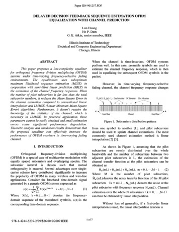
Paper ID# 901257.PDFTable 1. ITU-R M.1225 Vehicular Channel AWhere the integer m is the number of the input alphabet,the input sequence error is e(i) xfi) - x(i) , x(i) andxCi) are the input sequence and the estimation produced byEnvironmentthe algorithm. d min is the minimum distance achieved byTapan error event of the DDFSE trellis. w(A,) is the number ofsymbol errors entailed by an error event A" n is theduration of an error event A, .So when m M, f.l 1, n 1123456PM Q[.nlldmmll](20)IN;Where No 0-2 N 1C1 Min{E[hre(mL l)lrl}is(J'2AWGN power, N ICI is Inter Channel Interference power.The upper bound of symbol error probability for one taplinear equalization is given by [10]p' 2(M-l)Q[llfavrll]MM1 (21)N-lWhere N 0-2 N1C1 N E[lleint(k)112], f avr represents themean value of the estimated channel frequency responses,then Iid min 11 Ilfavr11 Obviously, it can be concluded from (20) and (21) that22PM P , as long as 0-2 NICI«Min{E[llepre(mL l)lrl}.Itmeans low level AWGN and Inter Channel Interference(ICI) power.So, in order to suppress the noise power, the length ofprediction filter, j, should not be too large. As for thedimension of U subspace, u , it could be an arbitrary"integer in [1, 1]. Although increasing f.l means more statesin trellis and better performance, it also brings aboutsignificantly extra computation complexity. It should bedetermined by trade-off between these two metrics.IV. SIMULATION RESULTSIn this section, the performance of the proposedapproach will be studied in a wireless time-variantRayleigh channel. The sampling rate is 10MHz, the digitalmodulation scheme is 16QAM, the number of subcarrier is256, and the carrier frequency is 2.3 GHz [13], theDoppler spread fD is 200 Hz and 400 Hz respectively. Asshowed in Table 1, the propagation parameters are inaccordance with the model of ITU-R M.1225 vehiculartest environment Channel A, which is widely used forperformance evaluation in both UMTS and IEEE 802.16.Relative delay(ns)0310710109017302510Average power(dB)0.0-1.0-9.0-10.0-15.0-20.0In simulation, 192 subcarriers are used to transmitdata symbols, 8 subcarriers are used to transmit pilotsymbols. The length of the prediction filter P(z) is j 2 .As for the parameters for U and V subspaces, f.l 1is used.The bit error rate under different Signal to Noise powerRatio is shown in Figure 4 (a) and (b).From Figure 4, for 10-3 bit error rate, it can befound that the proposed equalization method brings abouta processing gain over LMMSE interpolation, which isapproximately 4 dB for Fd 200 Hz and 1.5 dB in case ofFd 400 Hz.Compared to the ideal LMMSE algorithm, theproposed equalization method provides better performance.Since the number of pilot subcarriers is far less than that ofdata subcarriers, LMMSE is not so effective and itsperformance cannot be obtained in real applications. Themismatch LMMSE is the case where statistical parameters(for example, R llliP ' R HPHP and SNR ) used in the channelestimation have statistical error compared to real value. Itis common in practical applications. Obviously, theperformance degrades significantly.The new equalization approach proposed in thispaper does not require any pre-knowledge on the statisticsof the channel, thus secures the robustness of the systemperformance. Furthermore, it does not introduce anyoverhead, so it will not reduce the efficiency of the system.It can provide more performance gain at relatively highSNR. In this case, the Mean Square Error (MSE) of thechannel estimation plays a more important role than whitenoise in deciding the performance of the equalization. It isa typical scenario in MIMO-OFDM systems [14]. Theproposed approach will be beneficial to those MIMOOFDM systems.60f7
Paper 10# 901257.PDF 1 :: :: :: :: :: :: :: :: :: :: :: :: ::: :: -::: :: - ; J :: :: :: ::,:: :: ::- " . 'I1.10""Y"':: ,:::: I'.m,smatch LMMSE - - - - - --I -II---, ---I- ,- -[2]-fJ - proposed methodLMMSE interpolal ion' .J-e- Linear interpolation-I- ---I -I --.-I r r l r ' F[3]:::I:::J::: ::::I::::[:::I:::]::: III51015III25303540(a) BER performance for Fd 200 Hz r: :r :J C - - - r - - "T --- ., - ---1- -"ffi. 3 : - I10"I,,II[5]-fJ - proposed method.LMMSE interpolal ionmisma tc h LMMSE- - - -:- - "---;-,----"----,,,---:---J1"IIII[6]"'1"'1"'1" " "'1'"Qlro'"gw- - - r - - -iiiI10.2I - - - -, I- - -1- - -II- - I- -T - --I i - III-I -IIIIIII5101520SNR in dB253035- -I-1- - -I- 1- - -[7]III" - - - T - - --1 0-3 --;------!;:---,l;:---:!-:-- -----'-------'-----lo(b) BER performance for Fd40[8]2007 IEEE international symposium on ISPLC, pp.372 - 377, March 2007.Duel-Hallen, A., Heegard, C., "Delayed decisionfeedback sequence estimation," IEEE Transactionson Communications, vol. 37, issue 5, pp. 428 - 436,Mar 1989.Patwary, M.N ., Rapajic, P.B., Choi, J., "Decisionfeedback MLSE for spatially multiplexed MIMOfrequencyselective fadingchannel," lEE 400 HzFigure 4. BER performance under different SNRV. CONCLUSIONSIn this work, a novel equalization algorithm that issuitable for multicarrier transmission over rapidly timevarying channels is proposed. Analysis and simulationshow that it out-performs the traditional equalizer,commonly employed in OFDM systems. The extracomputational cost introduced by this algorithm is alsoreasonable.REFERENCES[1]IEEE 17th international symposium on PIMRC, pp.1-5, Sept. 2006.Cortes, J.A ., Tonello, A.M. , Diez, L., "ComparativeAnalysis of Pilot-based Channel Estimators forDMT Systems Over Indoor Power-line Channels," : : : : : : : D- - - T - - - I" - - -on Selected Areas in Communications, vol. 17, issue3, pp. 461-471, Mar 1999.Jeong-Wook Seo, Jung-Wook Wee, Won-Gi Jeon,Jong-Ho Paik Dong-Ku Kim , "An enhanced DFT-based channel estimation using virtual interpolationwith guard bands prediction for OFDM," 2006- B - Linear inlerpolationIon PIMRC, pp. 1-5, Sept. 2006.Ye Li, Seshadri, N., Ariyavisitakul, S., "Channelestimation for OFDM systems with transmitterdiversity in mobile wireless channels," IEEE Journal--- --- --- ----1---- --- ---4--ILLI352, Mar 2008.Tesi , R., Hamalainen, M., Iinatti, J., "ChannelEstimation Algorithms Comparison for MultibandOFDM," 2006 IEEE 17th international symposium[4] Kun-Chien Hung, Lin, D.W., "Optimal DelayEstimation for Phase-Rotated Linearly InterpolativeChannel Estimation in OFDM and OFDMASystems," IEEE Signal Processing Letters, pp. 349 -Proceedings on Communications, vol. 153, pp. 39 48, Feb 2006.[9] Arslan, H., Hui, D., "Soft bit generation for reducedstate equalization in EDGE," IEEE WCNC 2003,vol. 2, pp. 816 - 820, March 2003.[10] J. Proakis, Digital Communications, 5th ed. NewYork: McGraw-Hill, 2005.[11] Gerstacker, W.H., Obernosterer, F., Meyer, R.,Huber, J.B., "An Efficient Method for PrefilterComputation for Reduced-State Equalization," The11th IEEE International Symposium on PIMRC2000 , vol. 1, pp. 604-609,2000.[12] Kamel, N., Baharudin, Z., "Short term load forecastusingAI-Gharabally, M., Das, P., "Performance analysisof OFDM in frequency selective time-variantchannels with application to IEEE 802.16broadband wireless access," 2005 IEEE MilitaryCommunications Conference, vol. 1, pp. 351-356,Oct 2005.Burgautoregressivetechnique,"International Conference on IntelligentAdvanced Systems, pp. 912-916, Nov . 2007.2007and[13] IEEE Std 802.16e -2005 and IEEE Std 802.16 TM2004/Corl-2005, New York, 28 February 2006.[14] Yan Zhang, Hsiao-Hwa Chen, Mobile WiMAX:Toward Broadband Wireless Metropolitan AreaNetworks, New York: Auerbach Publications, 2007.70f7
based on the DDFSE, which is a sub-optimum MLSE algorithm. By using this algorithm, the equalizer can generate soft outputs for the channel decoder. On the other hand, the channel prediction module can be regarded as an integral part ofthe equalizer, and it uses the decision feed back generated by the equalizer to predict the channel