Transcription
'ALILEO 'ALILEI -EASUREWHAT IS MEASURABLEAND MAKE MEASURABLETHAT WHICH IS NOT Instruction ManualDMA 4500/5000Density/Specific Gravity/Concentration MeterSoftware Version: V5.012.c
Instruction ManualDMA 4500/5000Density/Specific Gravity/Concentration MeterSoftware Version: V5.012.c
While every precaution has been taken in the preparation of this document, Anton Paar GmbH assumesno responsibility for technical or printing errors or omissions.Nor is any liability assumed for damages resulting from the use of the information contained in thisinstruction manual.Anton Paar GmbH does not make a commitment to update the information in this manual. Specificationsare subject to change without notice.All rights reserved (including translation). No part of this document may be translated, reproduced ordistributed in any form (print, photocopy, microfilm or any other process) without the prior writtenpermission of Anton Paar GmbH.Trade marks may be used in this instruction manual without being marked as such. These are theproperty of their respective owners and are legally protected.Published by Anton Paar GmbH. Printed in Austria.Copyright 2005 Anton Paar GmbH, Graz, AustriaContact:Anton Paar GmbHAnton-Paar-Str. 20A-8054 Graz / Austria - EuropeTel: 43 316 257-0Fax: 43 316 257-257E-mail: info@anton-paar.comWeb: www.anton-paar.comDate: 04.05.2005Document number: XDLIB07Q.fm
Contents1 Introduction . 72 Safety Instructions. 83 Symbols in the Instruction Manual . 104 Supplied Items . 115 Putting into Operation . 136 Functional Components. 176.1Display and Keypad. 176.2Front View. 196.3Rear View . 207 General Settings . 217.1Display Contrast . 217.2Setting Date and Time . 217.3Setting the Language . 217.4Defining a Method. 217.5Setting the Temperature . 227.6Selecting the Output Data for Display, Printer and Memory . 227.7Defining the Display Contents and Layout. 237.8Defining the Printout Contents and Layout . 247.9Storing Measurement Values in the Memory. 257.10 Settings for the Sample Changer/Handling Unit . 257.11 Settings for the Measuring Procedure . 268 Checking Procedure, Adjustment and Calibration . 288.1Definitions . 288.2Checking Procedure: Density Check . 288.3Adjustment. 308.3.1Adjustment with Air and Water at 20 C . 308.3.2Adjustment with Air and Water for the Entire Temperature Range(Full Range Adjustment). 328.3.38.4Special Adjustment. 34Calibration. 369 Measurements. 3710 Cleaning and Drying the Measuring Cell . 4211 Operation . 4411.1 Menu Operation . 4411.1.1Using the Keys on the Keypad . 4411.1.2Using an External Keyboard (Optional). 4511.2 Menu Structure and Description . 45XDLIB0711.2.1"Logoff user "xxx"" . 4511.2.2"audit trail" . 455
11.2.3"temperature setting". 4611.2.4"adjustment" . 4711.2.5"measurement settings" . 5011.2.6"instrument settings". 5411.2.7"method settings" . 5711.2.8"sample changer configuration". 6711.2.9"user functions" . 6811.2.10 "custom function verification" . 7511.2.11 "data memory". 7511.2.12 External Cell . 7611.2.13 "testmode" . 7611.2.14 "service testmode". 7611.3 "Sample#" . 7711.3.1Automatic Set Temperature Change via "sample#" . 7812 Audit Trail . 8012.1 Introduction . 8012.2 Activating / Deactivating Audit Trail . 8012.2.1Activating Audit Trail. 8012.2.2Deactivating Audit Trail . 8212.3 Audit Trail Main Menu. 8312.4 Viewing the Audit Trail Log File . 8312.5 Printing the Audit Trail Log File. 8412.6 Exporting the Audit Trail Log File. 8412.6.1Verifying the Exported Log File . 8612.7 Clear Audit Trail . 8812.8 General Settings . 8912.9 User Management . 8912.9.1Adding a New User . 9012.9.2Removing a User. 9012.9.3Changing User Settings . 9112.9.4Print All User Settings . 9112.10 User Privileges. 91Appendix A:Operation at High Air Humidity and/or Low Measuring Temperatures . 93Appendix B:Technical Data . 95Appendix C:Commands for Communication between PC and DMA 4500/5000 . 98Appendix D:Density Tables . 102Appendix E:Possible Adjustment Errors, Adjustment Report. 107Appendix F:Software Versions . 110Appendix G:Wetted Parts. 112Appendix H:Menu Tree . 113Index. 1176XDLIB07
1 Introduction1 IntroductionThank you for buying the DMA 4500 or DMA 5000 density/specific gravity/concentration meter for gases and liquids. We greatly appreciate your trust andwill do everything we can to ensure that your instrument provides you with yearsof trouble-free operation.The DMA 4500/5000 is the first oscillating U-tube density meter which measureshighest accuracy in wide viscosity and temperature ranges.A unique reference oscillator, in addition to the U-tube oscillator, providesextraordinary long-term stability and makes adjustments at temperatures otherthan 20 C virtually unnecessary.By measuring the damping of the U-tube’s oscillation caused by the viscosity ofthe filled-in sample, the DMA 4500/5000 automatically corrects viscosity relatederrors.Two integrated Pt 100 platinum thermometers provide the highest accuracy oftemperature control, and are traceable to national standards.To perform a measurement, select one out of a total of 10 individual measuringmethods, and fill the sample into the measuring cell. An acoustic signal will informyou when the measurement is finished. Results are automatically converted(including temperature compensation where necessary) into concentration,specific gravity or other density-related units using the built-in conversion tablesand functions.The density results, including sample number or name, can be shown on theprogrammable LC display, printed out or transferred to the data memory.For fully automatic measurements, the DMA 4500/5000 can be connected to theautomatic sample changers SP-1m or SP-3m.The automatic SH-1 or SH-3 sample handling unit is another option for the densitymeters DMA 4500/5000.Some software features like temperature scan and adjustment at high density orviscosity are only available in the DMA 5000.XDLIB077
2 Safety Instructions2 Safety Instructions8 This instruction manual does not claim to address all of the safety issuesassociated with the use of the DMA 4500/5000 and samples. It is theresponsibility of the user to establish health and safety practices anddetermine the applicability of regulatory limitations prior to use. Before using the DMA 4500/5000, read this instruction manual completely. Anton Paar GmbH only warrants the proper functioning of the DMA 4500/5000 if no unauthorized adjustments have been made to mechanical parts,electronic parts and software, and the following points are adhered to. Follow all hints, warnings and instructions in the instruction manual to ensurethe correct and safe functioning of the DMA 4500/5000. Do not use the DMA 4500/5000 for any purpose other than described in theinstruction manual. Anton Paar GmbH is not liable for damages caused byincorrect use of the DMA 4500/5000. Do not use any accessories other than those supplied or approved by AntonPaar GmbH. The installation procedure should only be carried out by authorizedpersonnel who are familiar with the installation instructions. Do not operate the DMA 4500/5000 if a malfunction is suspected, ordamages, injuries or loss of life cannot be excluded under all circumstances. The DMA 4500/5000 is not an explosion-proof instrument and thereforemust not be operated in areas where there is a risk of explosion. Service and/or maintenance procedures which involve removing outsidecovers and working with the power switched on may only be performed byauthorized service personnel. Ensure that all operators are fully trained to use the DMA 4500/5000correctly and safely. Due to the nature of the measurement, the measuring results not onlydepend on the correct use and functioning of the DMA 4500/5000, but mayalso be influenced by other factors. We therefore recommend that theanalysis results are plausibility tested before consequential actions aretaken. Repair and service procedures may only be carried out by authorizedpersonnel or by Anton Paar GmbH. To lift the DMA 4500/5000, take the instrument with one hand on the frontside and one hand on the rear. Keep the instrument in front and close to yourbody.XDLIB07
2 Safety Instructions Follow the precautions below for the handling and measurement ofinflammable samples and cleaning materials:-Do not store inflammable material near the instrument.Do not leave sample containers uncovered.Clean all spillages immediately.Ensure that the DMA 4500/5000 is located in a sufficiently ventilated area,free from inflammable gases and vapors.Connect the DMA 4500/5000 to mains power via a safety switch located asafe distance from the instrument. In an emergency, turn off the powerusing this switch. Do not use the DMA 4500/5000 power switch.Keep a fire extinguisher at hand.Do not leave the DMA 4500/5000 unattended while in use.Do not touch areas marked with this symbol when the power is turnedon.XDLIB079
3 Symbols in the Instruction Manual3 Symbols in the Instruction ManualThe following symbols are used in the instruction manual:Warning:The "Warning" sign indicates a hazard to the operator.It calls attention to an operating procedure, practice, etc. which, if not correctlyperformed or adhered to, could result in injury or loss of life.Do not proceed beyond a "Warning" sign until the indicated conditions arefully understood and met.Important:The "Important" sign indicates a hazard to the equipment.It calls attention to an operating procedure, practice, etc. which, if not correctlyperformed or adhered to, could result in damage or destruction of theinstrument or parts of it.Do not proceed beyond an "Important" sign until the indicated conditions arefully understood and met.Hint:The "Hint" sign calls attention to any additional information which might beof use to the operator.10XDLIB07
4 Supplied Items4 Supplied ItemsHints: The DMA 4500/5000 has been tested and packed carefully beforeshipment. However, damage may occur during transport. If the DMA 4500/5000 or a supplied item has been damaged duringtransport, contact the transport firm as well as your local Anton Paarrepresentative. Keep the packing material for examination by the transportfirm or an insurance representative. If a part is missing, please contact your local Anton Paar representative.Pcs.1DMA 4500Cat.No. 75846DMA 5000Cat.No. 702441Power cordEurope: Cat.No. 65146USA:Cat.No. 52656UK:Cat.No. 618651Instruction manualEnglish: Cat.No. 75747German: Cat.No. 75746French: Cat.No. 136881Density standard,"Ultra pure water", 5 x 10 mlCat.No. 781691Accessory kitCat.No. 70248containing:2m7XDLIB07Item/Cat.No.Hose 3 x 5 mm siliconeCat.No. 50814Syringe 2 ml LuerCat.No. 5197411
4 Supplied ItemsPcs.12Item/Cat.No.2Injection adapter LuerCat.No. 122252Male Luer plug PTFECat.No. 638652Adapter Luer coneCat.No. 638631ScrewdriverCat.No. 750301Waste vesselCat.No. 6210XDLIB07
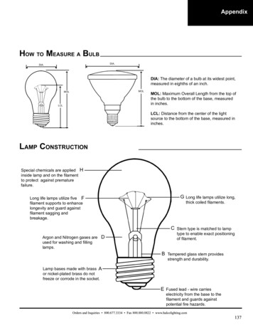
5 Putting into Operation5 Putting into OperationHints: The DMA 4500/5000 does not require any special installation conditions.The installation conditions should correspond to conditions in a typicallaboratory. However, to guarantee temperature stability, do not place theDMA 4500/5000- near a heater- near an air conditioner- in direct sunlight.Important:A strong built-in cooling fan dissipates heat through the bottom and the rear ofthe DMA 4500/5000. Ensure that the airflow is not blocked.Preparing the DMA 4500/5000 for the first start-up1. Take 2# injection adapters Luer from the accessory box.21Fig. 5 - 13Mounting the injection adapters Luer2. Carefully insert the injection adapters Luer (1) into the openings (2) of thefilling device until the tips of the adapters reach the openings of themeasuring cell.3. With moderate force, push the adapters towards the measuring cell.XDLIB0713
5 Putting into Operation4. Insert the screws (3) into the bore holes of the adapters and tighten thescrews until some resistance against further turning can be felt.Important:Do not screw in the screws (3) too tightly. The gap between the holding plateand the adapter (1) where the thread of the screw (3) becomes visible has tobe 3 to 4 mm (approx. 1/8"). If the screws are screwed in too tightly, themeasuring cell may be damaged.5. Check the connection of the adapters to the measuring cell for leaktightness: Close one adapter tightly with a finger.Fill air under moderate pressure through the other adapter using a 2 mlplastic syringe from the accessory box.Release the plunger of the syringe.If the connections are leak tight, the plunger of the syringe will be slowlypushed back by the pressure in the measuring cell.If the connections are leaking, no pressure was built up in the measuringcell and the plunger will not move. Repeat step 2 to 5.6. Cut a piece of approx. 250 mm length from the silicone hose contained in theaccessory box.7. Attach the silicone hose to the air pump outlet (see Fig. 5 - 2).Fig. 5 - 2Attaching the hose to the air pump8. Attach an adapter Luer cone (from the accessory box) to the other end of thesilicone hose (see Fig. 5 - 3).Fig. 5 - 314Attaching the adapter Luer cone to the hoseXDLIB07
5 Putting into Operation9. If a printer will be used, plug the interface cable into the COM 2 connector atthe rear of the DMA 4500/5000.10. Check the operating voltage.Important: Before switching the DMA 4500/5000 on, make sure that the correct linevoltage is available (AC 85 to 260 V, 48 to 62 Hz). If large voltagefluctuations are to be expected, the use of a constant voltage source(UPS) is recommended. The non fused earth conductor of the power cord (or power inlet) has tobe connected to earth.11. Connect the power inlet of the DMA 4500/5000 to the mains using the powercord.12. Turn on the DMA 4500/5000 using the "POWER" switch at the rear of theinstrument. The green light on the front indicates that the power is on. Afterthe start-up procedure the cell light is on continuously.Hints: After turning on the power, the DMA 4500/5000 needs approx. 20 minutesfor attemperating and additionally 5 to 10 minutes for internal temperatureadjustments. During this time "attemperating" is displayed. If the desiredmeasuring temperature is already set, do not touch any key during thistime as this will considerably increase the waiting period. In case of high air humidity or low measuring temperatures seeappendix A.13. As soon as the attemperating of the DMA 4500/5000 to 20 C is finished,perform a density check measurement, as described below.Important:The DMA 4500/5000 is factory adjusted and this control measurement shouldbe performed to check if the adjustment is still valid after transport.14. Press the menu" soft key and select "adjustment" in the main menu. Selectdensity check" and activate "density check settings".15. Enter the appropriate density value according to the water table in appendixD.16. Place the supplied waste vessel below the rear adapter (see Fig. 5 - 4) andconnect the adapter to the waste vessel with an appropriate hose (from theaccessory box).XDLIB0715
5 Putting into OperationFig. 5 - 4Placing of the waste vessel17. Open one bottle of the supplied liquid density standards (ultra pure water)and immediately introduce the liquid into the measuring cell of the DMA4500/5000. Use the supplied syringes and ensure there are no air bubbles inthe substance. Press OK.18. When the measurement is finished, either "density check: OK" or "densitycheck: not OK" appears on the display; additionally the measured densityand the deviation from the set value are displayed. If "density check: OK" is displayed, the instrument is ready for routinemeasurements.If "density check: not OK" is displayed, clean the measuring cell thoroughly(see chapter 10) and repeat the density check.Hint:The density of (ultra pure) water is 0.99820 g/cm3 at 20 C.19. If the result is still "density check: not OK", perform an air/water adjustmentat 20 C.Hint:The "density check" function can also be used when performing routinemeasurements in order to check the validity of the adjustment. Other densitycalibration liquids or standardized samples can be used.16XDLIB07
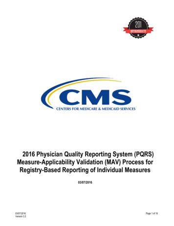
6 Functional Components6 Functional Components6.1Display and KeypadAfter turning on the DMA 4500/5000, the instrument carries out a self-test andinitialisation procedure (approx. 2 minutes) and then the following display isshown:Hint:It may be necessary to adjust the contrast of the display using the "UP" and"DOWN" keys (see Fig. 6 - 2). Save the contrast setting in the instrumentsettings" menu.AabBcdCFig. 6 - 1The display of the DMA 5000 at the first start-upA HeadlinePump"Pump" blinks, if the air pump is switched on.DensityName of selected method.-Osc-"-Osc-" in the right-hand corner indicates that the density cellis not oscillating. No density or related value will be displayedor printed, the display and printout show "------------".B Measuring window (example)Hint:The size and sequence of the displayed items can be changed in "Menu","method settings", "display configuration". Density and density-dependentvalues are only shown after the measuring temperature has been adjusted.XDLIB0717
6 Functional Componentsa)b)c)d)Date and timeDensity with automatic viscosity correctionSpecific gravity with automatic viscosityMeasuring cell temperature, state of the measurementC Bottom lineThe bottom line specifies the functions of the soft keys positioned on the keypadbelow. The functions change depending on the menu displayed.In the measuring mode the following soft key functions are available:MenuSelects menus for settings and configurations. Access to amenu can be restricted by a password.PrintStarts a printoutSample#For entering a sample text and/or numberMethodSelects a measuring method (see chapter 7.4)Start 18Starts an automatic measuring procedure. Depending onthe settings, the automatic measuring procedure includeswaiting for a stable measurement, printing the results andstoring them in the memory, freezing the display andincreasing the sample number.Starts the temperature scan, if activated (DMA 5000 only).If a sample changer SP-1m or SP-3m is connected andactivated, this soft key is not available. Use the "Start " keyon the sample changer.If an SH-1 or SH-3 sample handling unit is installed andactivated, this soft key is named "S-Start".XDLIB07
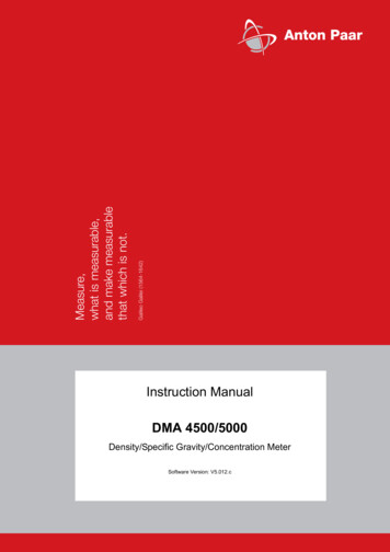
6 Functional Components6.2Front ViewBAHICFig. 6 - 2ABCDEFGHIXDLIB07DEFGFront view and keypadLC displayInspection window for the measuring cellSoft keys"UP" and "DOWN" keys" " key"PUMP" key for switching on the air pump"LIGHT" key for lighting up the display"HELP" keyGreen light indicates power-on19
6 Functional Components6.3Rear ViewMLKJIHGFAFig. 6 - 3BECDRear viewA "DRY AIR PUMP" nozzle for connecting a desiccator (see appendix A)B "DRY AIR INTERNAL" nozzle for supplying the interior of the DMA 4500/5000with dry air in order to prevent condensations on the cell block at lowmeasuring temperatures (see appendix A)C Power inletD Fuse holderE Power switchF Keyboard/bar code reader interfaceG Computer interface (COM 1)H Printer interface (COM 2)I Memory card drive (PCMCIA) for software updatesJ S-BUS interfaces for connecting a sample changer SP-1m or SP-3m or adensity measuring cell DMA HPK Type plateL Technical data shieldM Cooling fins20XDLIB07
7 General Settings7 General Settings7.1Display Contrast Make sure that the instrument is set to the measuring mode. The display contrast is adjusted by pressing the "UP" or "DOWN" keys. Save the setting of the display contrast permanently in the "instrumentsettings", "save display contrast" menu (see chapter 11.2.6).7.2Setting Date and TimeDate and time are set in the "instrument settings", "date & time" menu. Differentformats can be selected.7.3Setting the LanguageSelect the language (English or German) in the menu "instrument settings","language" (see chapter 11.2.6).7.4XDLIB07Defining a Method A method consists of the following settings: measuring temperature, displaysettings, printer and memory configuration, measurement settings andcontrol settings for the optional sample changer. These are all stored under aunique method name. By defining and storing a method you can set all parameters according toyour requirements. 10 different methods can be assigned. The 10 methods are factory preset, covering the most common measuringtasks. However, every method can be individually changed, adapted orrenamed. To activate a method, press the "Method" soft key and select a method fromthe list. To rename the method select "method settings", "edit method name". The factory setting for each method can be recalled by selecting "resetmethod" in the menu "method settings" (see chapter 11.2.7). To change or adapt the method, follow chapter 7.5 to chapter 7.11 in thegiven order.21
7 General Settings7.5Setting the TemperatureSet the temperature to degrees Celsius or Fahrenheit in "temperature setting"(see chapter 11.2.3).7.6 Selecting the Output Data for Display, Printerand MemorySelect the output data for the display, printer and memory from 7 generaldomains in the "method settings", "output selection" menu.Fig. 7 - 1 Select items by highlighting them and switching to "Y" ( Yes, activated). Use" " to toggle between "Y" and "N" ( No, not activated).Fig. 7 - 222Screen: Output selectionScreen: System Temperature Items set to "N" in the left-hand column are not assigned for output and willnot appear in the configuration lists for the display, printer and memory. Each method has its own output data selection.XDLIB07
7 General Settings7.7 Defining the Display Contents and LayoutSelect the items to be displayed and their size in "method settings", "displayconfiguration", "edit configuration".Fig. 7 - 3 Determine the size of the information on the display using the " " key totoggle between "S" (small), "M" (medium) "L" (large), and "N" (not selected).Example for the "edit display configuration" menu (depends on the "outputselection" settings):Fig. 7 - 4XDLIB07Screen: Display configurationScreen: Edit display configuration23
7 General Settings To list the selected items in your preferred order, highlight an item and moveit up or down using the "Mov Up" and "Mov Dn" soft keys.The above selection leads to the following display:Fig. 7 - 57.8 Defining the Printout Conte
Jul 1, 2021