Transcription
CAUTIONPLEASE READ THIS ESD USERHANDBOOK COMPLETELY BEFOREASSEMBLY.THESE PRODUCTSONLY HAVE THE ELECTROSTATICDISSIPATINGCHARACTERISTICSSPECIFIED IF PROPERLY USED ANDGROUNDED.Avoid damaging the ESD laminates and paintsin any way with sharp objects. Damaged, orirregularly maintained ESD protected worksurfaces can lead to loss of ESD protection.Keep non-conductors and unnecessary materials away from an ESD protected environment.Ensure that all users of the ESD working environment are aware of the necessity to observethe company’s ESD control standards.Correct assembly, operation, care, and maintenance of the ESD workstation are essential forESD compatibility. The customer is responsible for the ESD compatibility of all installations.Do not store, transport, or handle static sensitive components unless in an ESD safe environment.Always wear a wrist strap or other personalgrounding device when working at an ESD protected area.If you are missing any of the assembly instructions listed in this guide, please visit our websiteat: www.listaintl.com and search for “assemblyinstructions”.ESDUser Handbook
Table of ContentsIntroduction.2Definition of Symbols.3Definition of Terms.3Specifications.4Care and Use.4Testing Methods.5Isolation FAQ’s.6Cabinet Grounding.7Workbench Grounding.8Workbench Accessories.9What is ESD?Electrostatic Discharge (ESD) is a naturaloccurrence in which electricity is passedthrough our body, or other conductor, and discharges onto some object. For example, theshock we feel when we touch a doorknob is anESD. This natural occurrence is becoming avery hot topic in the field of electronics assembly due to the costly damage ESDs can causeto sensitive electronic equipment.What can a company do to preventESD Damage?A priority for any company with ESD concernsshould be to implement an ESD program andappoint an ESD Coordinator. For assistancewith the development of an ESD ControlProgram, refer to the ANSI/ESD standards20.20. It would be the objective of this program to reduce the potential for ESD relateddamage. One of the ways to do this is to carefully select and maintain the workstation. Thecosts associated with ESD damage far outweigh the capital investment needed to providean ESD protected workstation.What are the Resistivity Ranges?Conductive: Low resistance; carries electriccharge quickly. 105 Ω / squareDissipative: The increased resistance slowsthe transfer of charge from one point to another, offering increased protection during ESDevents. 105 and 1012 Ω / squareInsulative: High resistance; does not conduct electric charges well. 1012 Ω / squarePage 2
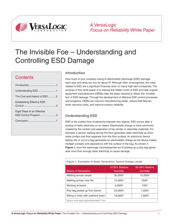
Definition of SymbolsEarth Ground:Connection to earth toestablish zero potential(voltage) using groundcord part number GCT.Common Ground Point:Point on the worksurfacethat is connected to earthground.Definition of TermsWrist straps (WS): Provides an electrical connection between the wearer’s skin andthe ground. Wrist straps keep the wearer at a low electrical potential at all times. Wriststraps are one of the most important steps in ESD control, solving 75-80% of all staticcontrol problems.Ground Cord Top (GCT): This is the main ground cord for workbench applications.This hardware connects a common ground point (Static Dissipative Top) to the earthground. Kit includes a brass stud with hardware, and a 9 foot cord with a 1M Ω resistor.Ground Cord Shelf (GCS): This hardware connects accessories (shelves, cabinets)to the established common ground point. Kit includes a brass stud with hardware, anda 9 foot cord without resistor.Resistor:Located on the Ground Cord Top (GCT) and the Wrist Strap (WS), acts asa fuse between the operator and ground. ONLY USE THE GROUND CORD WITHRESISTOR (GCT) BETWEEN THE EARTH GROUND AND THE COMMON GROUNDPOINT.Ground Loop: This occurs when there are more than one ground attached to an ESDprotected workbench. The primary ground cord (GCT) has a 106 Ω resistor in line toground. If a ground cord (similar to the third wire on most electrical components) isused, there is no resistor, and this is an easier path to ground. This is not desired, andshould be avoided.Page 3
SpecificationsESD Paint: Entirely covers workbench accessories, the cabinet housing and drawersof a cabinet if specified. The ESD painted drawers will transmit the chargethrough bearings and the drawer track to the grounded cabinet.Surface Resistance:105 - 109Ω (measured at 100V)Static Dissipative (SD) Tops and Shelves: Contain a “carbon scrim” dissipativelayer which conducts the charge away from the workbench.Point to Point Resistance, per EOS/ESD - S4.1:At 40-60% RH*:106 - 107 ΩAt 20-40% RH*:107 - 108 ΩAt 10-20% RH*:108 - 109 ΩPoint to Ground Resistance, per EOS/ESD - S4.1:At 40-60% RH*:106 - 107 ΩAt 20-40% RH*:107 - 108 ΩAt 10-40% RH*:108 - 109 ΩStatic Decay Rate: per FMTS 101C, method 4046:At 50% RH*:0.01 secondsAt 10% RH*:0.02 seconds(* Relative Humidity)Conductive Plastic Insert Boxes and Slotted Grooved Trays: Conductive boxes aremolded from a permanantly conductive high impact polystyrene compound (PS-723), toprovide protection from electrostatic discharge.Surface Resistivity:200 Ω/squareCare and Use Avoid damaging ESD laminates and paint with sharp objects. This can affect the ESDprotective properties. All ESD protected areas require regular care and maintenance, as well as checks andinspections. These are on going user responsibilities. Damaged ESD work surfaces can lead to loss of ESD protection. Check all ESD installations regularly for damage, wear and tear. Failure to do so mayresult in loss of ESD protection. Check the ESD workstation’s protection characteristics frequently. See your ESDCoordinator for further information. Clean all surfaces periodically, using a plain cotton rag with a good ammoniated detergent. Dust and dirt may cause conditions that cause electrostatic discharge. Do not use cleaning materials containing wax or aggressive solvents that may modifythe electrical properties of the worksurface. Do not use brushes or other abrasive cleaning implements.Page 4
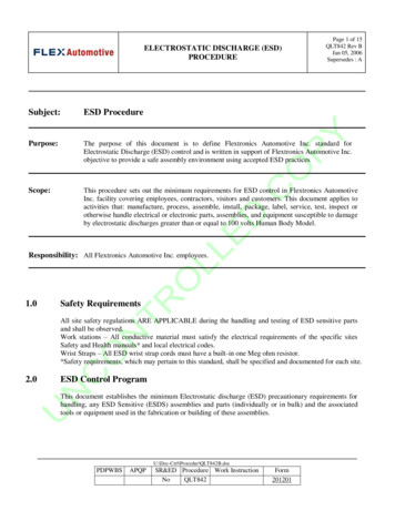
Testing MethodsElectrostatic dissipative workstation resistance properties are measured using aMegohmmeter. ESD Association standard S4.1 recommends using a measuringapparatus capable of delivering 10 ( 1) volts and 100 ( 10) volts using two 5 poundelectrodes.ResistancetoGround(orGroundable Point) measures thetotal resistance between the surfacethrough the ground cord. According toEOS/ESD - S4.1, resistance to groundshould be measured using the apparatus listed above with one electrodeplaced on the surface and the other terminal connected to a groundable point.The resistance shouldmeasure69between 10 and 10 ohms.Point to Point Resistance (or SurfaceResistance) is the resistance measuredbetween two points on a static controlsurface. According to EOS/ESD - S4.1,using the apparatus listed above, theelectrodes should be spaced ten inchesapart and at least two inches from theedge of the surface. The resistanceshould measure 1MΩ. SurfaceResistivity is a test used to measurehow freely charges flow through a material (measured in Ω / square). It is generally used to measure items that arenot typically grounded directly.For additional information, or to get copies of the ESD standards or test methods, visitthe ESD Association website at http://www.esda.org.Page 5
Isolation FAQIf your workbench includes electrical components, you must isolate those componentsfrom the workbench to ensure proper grounding.What is the benefit?Isolation of electrical components helps ensure that the electric charge dissipated fromthe worksurface goes through the correct path to ground (through the ground cord withthe 1 M-Ω resistor). Electrical components (with third wire ground) do not have thisresistor, making it a quicker path to ground, unless this path is isolated from thecharge.How is this done?Electrical charges look for the quickest path to ground. Since the electrical grounddoes not have any resistance, this path is quicker than the primary worksurfaceground. Adding insulative hardware or pads between the electrical products and theproduct they attach to prevent this path from occuring.How do we make sure it works?Testing the overall bench:Using a Megohmmeter, the workbench resistance to ground should measure at least106 ohms. Perform this test by measuring the resistance between the brass commonground stud (which you installed on the bench) and the earth ground. If the resistanceis less than 106 ohms, then there is a ground loop, and it must be isolated from thebench.Testing individual components to ensureisolation:Using a Megohmmeter, measure thepoint to point resistance between allconnection points of an electrical connection (power strip, light, etc), and theelectrical outlet ground wire. The resistance should be greater than 106 ohmsor this will be a path to ground.Page 6
Grounding Instructions for ESD Painted CabinetsStand Alone Cabinets Determine where you want to install the ground cord;this location should be installed in the top or bottomcovers of the cabinet and should be at least 5 inchesfrom the front/rear of the cabinet. Using a center punch, create an indentation in the cabinet housing. Use a drill with a #19 (.166 inch) drill bit to drill the holeinto the cabinet. Insert the 10-24 x ½” self threading screw through theeye of the ground cord and screw into cabinet. The endof the ground cord closest to the inline resistor shouldbe connected to this point. This is your commonground point. Drawers do not need to be grounded, as the charge istransferred through the metal components connectingthe drawer to the cabinet housing. Always test yourcabinet to ensure proper grounding.Multiple In-line Cabinets Ground your first cabinet as per the stand alone cabinet instructions. The row of cabinets should be bolted together, if they aren’t already, for proper grounding. One of the bolts should include a metal lock washer on both the nut side and thebolt side of the cabinets. This will ensure that you are getting a clean connection to thecabinet ground. Always test your cabinet configuration to ensure proper grounding.Stand Alone Cabinet with Static Dissipative Counter Top Remove the top drawers of the cabinet. The Brass Ground Stud will be used to connect the static dissipative top to the cabinet. Determine a location for the brass groundstud, keeping in mind that the counter top is connected to the cabinet using lag screwsinside the cabinet. This location should be at least 2 inches from the edge of thecounter top. Using a drill with a 5.5mm (7/32") drill bit, drill into the static dissipative top, through thecabinet housing. It is important to use the correct sized drill bit to ensure propercontact with the conductive "scrim" layer of the counter top. Place the ground stud in hole and use a hammer to tap the "knurled" end of the studinto the top. Fasten the ground stud using the brass nut, with the brass washer in between, thenfollow the instructions for the Stand Alone Cabinets.Always test your workstation to ensure proper grounding.Page 7
Workbench Grounding InstructionsWorkbenches with Static Dissipative tops Using a drill with a 5.5mm (7/32”) drill bit, drill into the Static Dissipative top. It is important to use the correct sized drill bit to ensure proper contact with the conductive“scrim” layer of the counter top. Place the ground stud in hole and use a hammer to lightly tap the “knurled” end into thetop. Fasten the ground stud using the brass nut, with the brass washer in between. This isyour common ground point. Attach the primary ground cord from the common ground point to an approved grounding location. The end of the ground cord closest to the inline resistor should be connected to this point.All electrical equipment used at an ESD workstation should be connected to GroundFault Circuit Interrupt (GFCI) outlets.*Note: Cabinets and other accessories may also be connected to the workbench common ground point using the cabinet grounding instructions. If you are connecting to acommon ground point, you should not use a ground cord with a 1 M-Ω resistor. ONLYUSE THE GROUND CORD WITH RESISTOR (GCT) BETWEEN THE EARTHGROUND AND THE COMMON GROUND POINT.Once your workbench is assembled, it is important to test the overall benchgrounding system to the common ground point .Page 8
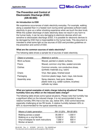
Workbench Accessory Grounding InstructionsGCSRiser Support with GFCIOutletsScrewNylon ShoulderWasherStatic Dissipative Shelves Similar to the instructions for the StaticDissipative top, determine the location of theground stud, drill and then tap the ground stud intoyour shelf. Using the ground cord without the resistor (GCS),connect your shelf to the common ground point.Shelves should not be connected directly toground.Instrument Riser Shelf Supports (IRSS)To isolate powered instrument riser shelves, follow the instructions shown in the WorkbenchAssembly Instructions. Please incorporate thefollowing steps into these instructions: After drilling the pilot holes and before fasteningthe IRSS to the bench top, place the isolationpad between the IRSS and the Static DissipativeTop, making sure the holes line up. Insert four ؼ" x 1/16" long nylon shoulder washers into the holes at the bottom of the IRSS. Fasten IRSS with the screws provided and finish the installation using the WorkbenchAssembly Instructions.Isolation PadOnce your bench is assembled, it is important to test the overall bench grounding system to ensure proper grounding and isolationfrom ground loops.Note: Isolation is not required between theunderside of the upper shelf (the core of theshelf) and the IRSS, unless there is a bullnose(radius) front or rear edge and the laminate is incontact with the IRSS.Page 9
FlexworksShelves painted with static dissipative paint,used in conjunction with static dissipative tops,are grounded using the workbench groundsystem (through the common ground point).When the Flexworks system is screwed intothe static dissipative laminate, the screw conducts the charge to the top, which carries thecharge to the workbench ground point, wherethe charge is brought to ground through the 1M-Ω resistor.Isolation is necessary to ensure that thischarge does not go directly to ground throughany of the attached electrical components.The following instructions cover the standardelectrical components Lista offers in Flexworksapplications. Other applications, outside thescope of Lista's standard product application,will require similar consideration.Nylon ShoulderWasherOverhead LightSupport BracketFront ProfilePage 10Overhead LightAssemble the Flexworks starter and addersections according to the Assembly and UseInstructions for Flexworks Accessory System,included with your shipment. Please incorporate the following instructions into your installation:While mounting the pivot bracket to theFlexworks Light bracket, insert a ؼ" x 1/8"long nylon shoulder washer into the Flexworkslight support bracket. Make sure that theshoulder goes into the crescent moon shapeof the light bracket and the flat part of thewasher goes between the pivot bracket andthe light support bracket, as shown in the figure below.Note: Other utility lights (FLF-18, for example)should be attached using the magnetic stripsprovided, and not using nuts and bolts or tekscrews. The magnetic strip acts as an insulator. In some cases, the weight of the lightmay be more than the magnet can support.Screws may be used, but must be isolatedfrom metal objects accordingly.
Horizontal Power RailFlexworks PostFW Isolation PadNylon ScrewFollow the instructions included with your shipment for installation of the Flexworks HorizontalPower Rail, shown in the Assembly and UseInstructions for Flexworks Accessory System.Include the following steps in your installation toensure proper isolation.Remove the adhesive backing from the isolationpad and attach it to the bracket at both ends ofthe power rail. Following the FlexworksAccessory Installation Instructions, substitute thefour ؼ-20 x ½" Nylon Screws for the metalhardware.Vertical Power StripShoulder WasherWhile following the Flexworks AccessoryInstructions included with your shipment, pleaseinclude the following steps:Bracket“Mushroomed”shoulder washerBefore attaching the power strip to the bracket,use a ؼ" x ¼" nylon shoulder washer betweenthe power stip and the bracket. Make sure theflat part of the washer is between the two andthe shoulder sticks through the bracket. Pleaserefer to the figures to the left for more detail.As you fasten the power strip using the hardwareprovided, the shoulder should "mushroom"around the head of the screw. This will isolatethe power strip from the bracket.Outlet StripBracketOnce your bench is assembled, it is important to test the overall bench grounding system to ensure proper grounding and isolationfrom ground loops.Page 11
Wrist Strap (WS)Ground Block (GB)Wrist Strap (WS) & Ground Block (GB) Choose a location under your workstation to placethe Ground Block. Using the 2 #8 self-tapping screws, screw the GroundBlock into the underside of the workbench top. Connect the ground block directly to the earthground. There is a 1 Mega-ohm resistor alreadyincorporated into the wrist strap. Connecting theground block to the common ground point wouldincrease the resistance to ground, causing a resistance that may be outside acceptable limits. Cableclips are included for wire management. Connect up to two Wrist Straps to the Ground blockusing the banana jacks built into the front of theGround Block. Always test your wrist strap/groundblock to ensure proper grounding.Lista International Corp.106 Lowland StreetHolliston, MA 01746-2094 USACustomer Service: (800)722-3020Telephone: (508) 429-1350Fax: (508) 626-0353E-mail: sales@listaintl.comwww.listaintl.comDocument Number: MD023A3, Rev 2, 10/2001 2001 Lista International, all rights reservedISO 9001 Certified
ESD Damage? A priority for any company with ESD concerns should be to implement an ESD program and appoint an ESD Coordinator. For assistance with the development of an ESD Control Program, refer to the ANSI/ESD standard s20.20. It would be the objective of this pro-gram to reduce the potential for ES