Transcription
General Electric Systems Technology ManualChapter 2.6Condensate and Feedwater Systems
TABLE OF CONTENTS2.6 CONDENSATE AND FEEDWATER SYSTEMS . 12.6.1 Introduction . 22.6.2 System Description . 22.6.3 Component Descriptions . 32.6.3.1 Main Condenser . 32.6.3.2 Condenser Hotwell . 52.6.3.3 Condensate Pumps . 52.6.3.4 Steam Jet Air Ejector Condensers . 62.6.3.5 Steam Packing Exhauster . 62.6.3.6 Condensate Demineralizers . 62.6.3.7 Exhaust Hood Spray. 72.6.3.8 Exhaust Hood Spray Line Flow Paths . 72.6.3.9 Condensate Booster Pumps. 82.6.3.10 Drain Coolers . 82.6.3.11 Low Pressure Feedwater Heaters . 82.6.3.12 Heater String Isolation Valves . 102.6.3.13 Non-Return Check Valves . 102.6.3.14 Reactor Feedwater Pumps . 112.6.3.15 High Pressure Feedwater Heaters . 122.6.3.16 Feedwater Discharge Piping . 122.6.3.17 Feedwater Heater Drains . 122.6.3.18 Condensate and Demineralized Makeup Water System . 132.6.4 System Features and Interfaces . 142.6.4.1 Normal Operation . 142.6.4.2 System Startup . 152.6.4.3 Condensate and Demineralized Makeup Water System . 162.6.4.4 System Interfaces . 162.6.5 Summary . 18Rev 09/112.6-iUSNRC HRTD
LIST OF -92.6-102.6-112.6-122.6-132.6-142.6-15Rev 09/11Condensate SystemFeedwater SystemCondenser Flow PathsTypical Horizontal Feedwater HeaterTypical Vertical Feedwater HeaterReactor Feed Pump TurbineReactor Feed Pump Oil SystemMoisture Separator ReheaterExtraction SteamHeater Drain FlowsCondensate and Demineralized Makeup Water SystemNon-Return Check ValveExhaust Hood FlowCondensate DemineralizerCondensate Demineralizer Process System2.6-iiUSNRC HRTD
2.6 CONDENSATE AND FEEDWATER SYSTEMSLearning Objectives:1. Recognize the purposes of the Condensate and Feedwater system.2. Recognize the purpose, function and operation of the following Condensate andFeedwater system major components:a. Condensate Storage Tankb. Main Condenserc. Main Condenser Hotwelld. Condensate Pumpse. Steam Jet Air Ejector Condenserf. Steam Packing Exhausterg. Condensate Demineralizersh. Condensate Booster Pumpsi. Low Pressure Heatersj. Feedwater Pumpsk. High Pressure Heatersl. Feedwater Flow Detectors3. Recognize the following flow paths of the Condensate and Feedwater system :a. Normal full power operationb. Hotwell Level Controlc. Startup level controld. Long Cycle Cleanupe. Short Cycle Cleanup4. Recognize how the system will respond to Condensate Booster Pump Low SuctionPressure and Feedwater Pump Low Suction Pressure5. Recognize how the Condensate and Feedwater system interfaces with the followingsystems:a. Circulating Water System (Section 11.1)b. Control Rod Drive System (Section 2.3)c. Feedwater Control System (Section 3.3)d. Reactor Water Cleanup System (Section 2.8)e. High Pressure Coolant Injection System (Section 10.1)f. Reactor Core Isolation Cooling System (Section 2.7)g. Main Steam System (Section 2.5)h. Offgas System (Section 8.1)Rev 09/112.6-1USNRC HRTD
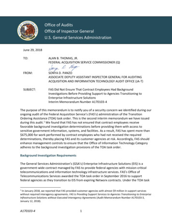
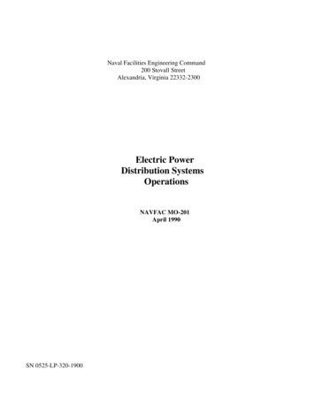
2.6.1 IntroductionThe Condensate and Feedwater chapter includes information relating to the processingand preparing water for use in reactor systems, and the movement of water from themain condenser to the reactor vessel.The purposes of the Condensate and Feedwater system are to: condense steam from the main and feed pump turbines and collect steam drains viathe main condenser, remove non-condensible gases from the main condenser, purify and preheat water prior to injection into the reactor vessel, supply the driving head to pump water from the main condenser to the reactorvessel, provide injection path for High Pressure Coolant Injection system to the reactorvessel, provide injection path for Reactor Core Isolation Cooling system to the reactorvessel, provide a path for returning Reactor Water Cleanup system to the reactor vessel.The Condensate and Demineralized Makeup Water System stores and distributesreactor quality water for the main steam cycle and for numerous auxiliary systems. Italso maintains a minimum of 150,000 gallons for the Reactor Core Isolation Cooling andHigh Pressure Coolant Injection systems.The functional classification of the Condensate and Feedwater System, andCondensate and Demineralized Makeup Water system is that of a power generationsystem.2.6.2 System DescriptionThe Condensate and Feedwater System shown in Figures 2.6-1 and 2.6-2, is anintegral part of the reactor plant regenerative steam cycle. The steam exhausted fromthe low pressure turbines is condensed in the main condenser and collected in the maincondenser hotwell. The main condenser also receives drainage from various systemand equipment drains. The condensate that is collected in the hotwell is removed bythe condensate pumps. The condensate pumps provide the driving force for thecondensate flow through the steam jet air ejector (SJAE) condensers and steampacking exhauster. The SJAE condensers and the steam packing exhauster heat thecondensate flow while cooling their respective process flows. Condensate flow is nextdirected to the condensate deep-bed demineralizers which purify the condensate waterthrough ion exchange and filtration. Condensate booster pumps take suction from thedemineralizers and maintain the driving force of the condensate flow through strings oflow pressure feedwater heaters. The feedwater heaters take extraction steam and hotwater from the main turbine and moisture separator reheaters to further raise thecondensate temperature. The feedwater pumps take suction from the low pressureRev 09/112.6-2USNRC HRTD
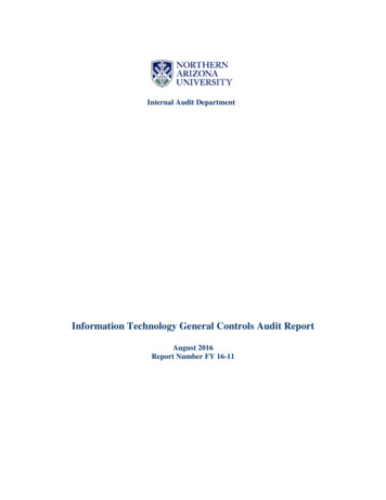
feedwater heaters and develop system pressure high enough to inject into the reactorpressure vessel. The amount of feedwater flowing to the reactor pressure vessel duringnormal operations is controlled by varying the speed of the turbine driven reactor feedpumps. During very low power operations the feedwater flow rate is maintained by RFPStart-up Level Control throttle valves. The discharge of the feedwater pumps is directedto the two high pressure feedwater heaters. This final stage of feedwater heating isprovided by extraction steam from the high pressure turbine. High temperature andpressure feedwater is directed to two feedwater lines that penetrate the primarycontainment. These feedwater lines further divide into a total of four reactor pressurevessel feedwater spargers. The feedwater spargers distribute feedwater within thereactor pressure vessel annulus where it is mixed with water rejected by the steamseparators and steam dryers.The Condensate and Demineralized Makeup Water system, (Figure 2.6-11) consists ofa series of storage tanks, transfer pumps, and demineralizers providing reactor grademakeup water to a variety of balance of plant systems. Demineralized water isproduced by a series of Demineralized Makeup Water Demineralizers and transferpumps to maintain the Demineralized Water Storage Tank (DWST) full of water. Shouldthe Condensate Storage Tank (CST) level drop below predetermined water levelsdemineralized water is automatically transferred from the DWST using theDemineralized Water Transfer pumps. The CST supplies water to the condensatetransfer pumps, the Control Rod Drive Hydraulic System pumps, and the condensermakeup. A separate connection to the CST is used to supply water for the HighPressure Coolant Injection (HPCI) system, Reactor Core Isolation Cooling (RCIC)system, and Core Spray system pumps. The Core Spray system pump connection isprimarily used for system testing.2.6.3 Component Descriptions2.6.3.1 Main CondenserThe main condenser, shown in Figure 2.6-3, consist of two deaerating, single pass,single pressure, radial flow type surface condensers with divided water boxes. Each ofthe condensers is located beneath one of the two low pressure turbines with thecondenser tubes running perpendicular to the turbine-generator axis. The maincondenser receives cooling water from the Circulating Water System. Circulating waterflows through the condenser tubes, condensing the low pressure turbine exhaust steamsurrounding the tubes.During normal operation, steam from the low pressure turbine is exhausted directlydownward into the condenser shells through exhaust openings in the turbine casing.As turbine exhaust flows downward the area increases, reducing the velocity of theexhaust steam. By lowering the exhaust steam velocity, the vibration and erosionexperienced by the upper rows of tubes is minimized.Rev 09/112.6-3USNRC HRTD
The condenser neck section of each condenser directs low pressure turbine exhauststeam to the condenser tube section. In addition to directing steam, the condenserneck houses two low pressure feedwater heaters, a drain cooler, and extraction steampiping. The low pressure feedwater heaters, drain cooler, and extraction steam pipingthat are located in the condenser neck are lagged with stainless steel insulating panels.The insulating panels minimize heat loss to the condenser.A rubber belt type expansion joint is installed between the low pressure turbine and thecondenser neck to permit differential expansion.The condenser section internals establish circumfluent flow from the low pressureturbine exhaust to the condenser tube section. The remaining mixture ofnoncondensible gases and water vapor are then directed to the air cooler section.The air cooler section consists of a vent duct and tube bundle enclosed by the air coolerbaffle. The air cooler baffle is open at the bottom to direct all the remainingnoncondensible gases and water vapor upward through the tube bundle. In passingthrough the tube bundle the mixture of noncondensible gases and water vapor iscooled, reducing its volume. The remaining mixture flows toward the colder end of theair cooler and the vent duct outlet.The vent duct directs the steam mixture to the offgas penetrations where it will befurther processed (Offgas System, Section 8.1).The condenser units also serve as a heat sink for other systems, including: exhaust steam from the reactor feed pump turbines turbine bypass steam cascading low pressure heater drains air ejector condenser drains steam packing exhauster condenser drains feedwater heater shell operating vents moisture separator reheater (Figure 2.6-8).Other systems periodically exhaust/drain to the main condenser sections, such as: startup vents of the condensate pumps, condensate booster pumps, reactor feedpumps return lines of the condensate pumps, condensate booster pumps, reactor feedpumps low pressure feedwater heater shell and minimum recirculation flowRev 09/112.6-4USNRC HRTD
Most of these return lines to the condenser contain steam or a mixture of steam andwater vapor and exhaust to the main condenser below the tube bundle to prevent: Overheating the condenser tubes Disturbing the main turbine exhaust flow Overheating the turbine shellTurbine bypass steam enters the condenser above the bundles due to the large steamflow which may be up to 25% of rated steam flow.To ensure equal pressure between the condenser shells, cross-connect pipes areprovided between the upper portions of the condenser tube nest.2.6.3.2 Condenser HotwellThe condenser hotwells are incorporated in the bottom of each condenser shell andserve as collection points for all condensate. The hotwell for each shell is integral with,and a continuation of, the condenser shell side plates. The hotwells are tied togetherwith 24 inch equalizing lines to ensure equal level in both hotwells.Each hotwell is designed to store a sufficient quantity of condensate to provide aminimum of 2 minutes effective retention of all condensate entering the hotwell forradioactive decay of N16 (t1/2 7.11 seconds). Retention time is ensured from normalwater level to minimum operating level by use of a horizontal collector plate under thetube bundles. The plate directs the condensate to the end of the hotwell opposite thecondensate pump suction pipe. Additional storage volume, over and above the
Rev 09/11 2.6-2 USNRC HRTD 2.6.1 Introduction The Condensate and Feedwater chapter includes information relating to the processing and preparing water for use in