Transcription
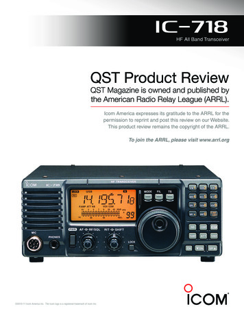
PRODUCT REVIEWICOM IC-718 HF TransceiverReviewed by Steve Ford, WB8IMYQST Managing EditorAnticipating a larger number of HF operators in the wake of license restructuring, manymanufacturers are eager to introduce newlower-priced HF transceivers. ICOM’s entryin the race is among the first out of the gate:the IC-718.At approximately 4 9 9 inches, the IC718 is a compact desktop rig with a functional“military” appearance. The front panel is dominated by a sizeable amber LCD display, largeVFO tuning knob and forward-firing speaker.Concentric AF and RF/SQL gain pots are positioned immediately below the display alongwith concentric RIT and IF SHIFT controls. Buttons you are likely to use most often—MODE,FILTER and TS (tuning step)—are prominentand easily accessible above the VFO knob.Most of the remaining buttons, includingthe direct-entry frequency keypad, occupythe right side of the front panel. Althoughthe trend during the past several years hasbeen to use modular microphone jacks and1/8-inch headphone jacks, the IC-718 reverts tothe more traditional 8-pin conventional mikeconnector and 1/4-inch headphone jack.The rear panel lineup is refreshinglyspartan. There is an SO-239 antenna port,a “standard” 6-pin Molex dc power jack, anantenna tuner control jack (for use withICOM’s external autotuners), and a 13-pinaccessory jack. Jacks are also provided forcomputer control (using ICOM’s optionalCT-17 CI-V level converter), external speakerand CW key or paddle. There are separateRCA-type ALC and SEND jacks for controllinglinear amplifiers.The IC-718 provides 100 W on SSB, RTTYand CW and 40 W on AM. The RF poweroutput is continuously variable betweenapproximately 5 and 100 W (from 2 to 40W on AM).The No-Manual TestLike any kid with a new toy, I tend to bemore than a little impatient. When I popopen the box and catch the first whiffs ofthat new-radio fragrance, the last thing Iwant to do is read documentation. I want touse the radio now!In the time-honored tradition of redefining one’s own personality defects as anaptitude for creativity, I’ve devised the“no-manual” test. Not only is it an expedientway to determine the user friendliness ofa radio, the no-manual test satisfies my inability to defer gratification.The concept is simple: use the manual tohook up the various cables, then toss it aside.The idea is to see how long it takes to get theradio on the air using your own intuition.I’m an IC-706MKII user, so hooking up theIC-718 was particularly easy. I just unpluggedthe IC-706MKII cables and swapped them ontothe ’718. This included the control cable for myICOM AH-4 remote-controlled antenna tuner.I use this device to feed a 90-foot length ofwire strung between my tool shed and a treein my backyard.Pressing the front-panel PWR button,the IC-718 awoke with a metallic ka-thunk.Let’s see if the IC-718 is anything like myIC-706 the front panel DN/UP buttons shouldstep me through the band selections. Bingo.I jumped to 10 meters, selected USB, setthe RF/SQL control to fully clockwise andturned up the audio.Nothing!The S meter was twitching madly, butthe speaker was utterly dead. Was theBottom LineThe ICOM IC-718 offers a nice collection of the more desirable features that aretypically absent from transceivers in its priceclass.control set for maximum squelch? I spun thering full counterclockwise, which I assumedwould be the open-squelch position. Stillnothing.Now what? Was it time to admit defeat andread the manual? After a few more minutesof futile experimentation I decided to resortto the manual.Sure enough, the answer to the mysteryappeared on page 15. I discovered thatthe default configuration of the ring is tofunction as an RF gain control betweenthe 7 o’clock and 12 o’clock positions, anda squelch from the 12 o’clock to 5 o’clockpositions. I followed the instructions in themanual, set the contol to 12 o’clock and wasrewarded with a flood of audioSubsequent manual reading revealedthat you can access the IC-718’s menu systemand redefine the dual-function ring configuration, choosing to have the ring act strictlyas an RF gain or squelch control. I used aset-mode menu to set the ring to functionsolely as an RF gain adjustment and livedhappily ever after.The IC-718 makes use of two menus—a“quick set” and an “initial set” menu. There are13 quick set menu selections that include theRF power output level, a three-step displaydimmer (high, low or off), mike gain and VOXsettings, and a handful of choices related toCW and RTTY operation.Joe Bottiglieri, AA1GW Assistant Technical EditorJuly 200063
The initial set menu includes selectionsfor controlling a peak-hold function for themeter, a mode lockout feature, key beep, CWsidetone level, scan speed and resume condition, RF/SQL control behavior, key type andpaddle sense, and some additional settingsassociated with the optional accessories.The various menu selections are identified with alphanumeric character strings upto 8 characters long, so it’s easy to find thespecific setting you’re looking to change.Once the mystery of the ring was solved,the rest was easy. I punched the TUNERbutton and my AH-4 dutifully responded,tuning my end-fed wire for a 1.3:1 match on10 meters. I answered a CQ and received afine signal report from a station in Spain. Onthe-air reports indicated that the suppliedhand mike produced clear transmit audio,even when I activated the ’718’s fixed-levelspeech compressor.Table 1ICOM IC-718, serial number 001069Manufacturer’s Claimed SpecificationsFrequency coverage: Receive, 0.03-30 MHz;transmit, 1.8-2, 3.5-4, 7-7.3, 10.1-10.15,14-14.35,18.068-18.168, 21-21.45,24.89-24.99, 28-29.7 MHz.Power requirement: Receive, 2.0 A; transmit, 20 A (maximum).Modes of operation: SSB, CW, AM, AFSK, FSK.Measured in the ARRL LabReceive, as specified1; transmit, 1.8-2, 3.4-4,7.0-7.5, 9.9-10.5, 13.9-14.5. 17.9-18.5,20.9-21.5, 24.4-25.1, 28-30 MHz.Receive, 1.7 A; transmit, 18 A. Tested at 13.8 V.As specified.ReceiverReceiver Dynamic TestingSSB/CW sensitivity, bandwidth not specified,Noise Floor (mds), 500 Hz filter:10 dB S/N: 1.8-30 MHz, 0.16 µV.Preamp offPreamp on1.0 MHz–120 dBm–129 dBm3.5 MHz–129 dBm–137 dBm14 MHz–130 dBm–139 dBmAM sensitivity, 10 dB S/N: 0.5-1.8 MHz,10 dB (S N)/N, 1-kHz tone, 30% modulation: 13 µV; 1.8-30 MHz, 2 µV.Preamp offPreamp on1.0 MHz5.4 µV1.8 µV3.8 MHz1.8 µV0.7 µVBlocking dynamic range: Not specified.Blocking dynamic range, 500 Hz filter:Preamp offPreamp on3.5 MHz123 dB*121 dB*14 MHz120 dB*119 dB*Two-tone, third-order IMD dynamic range: Not specified.Two-tone, third-order IMD dynamic range, 500 Hz filter:Preamp offPreamp on3.5 MHz88 dB87 dB14 MHz87 dB85 dBThird-order intercept: Not specified.Preamp offPreamp on3.5 MHz 10.4 dBm–2.3 dBm14 MHz 6.8 dBm–9.3 dBmSecond-order intercept: Not specified.Preamp off, 54 dBm; preamp on, 55 dBm.S-meter sensitivity: Not specified.S9 signal at 14.2 MHz: preamp off, 149 µV2; preamp on, 38 µV.Squelch sensitivity: SSB, CW, RTTY, 5.6 µV.At threshold, preamp on: SSB, 6.4 µV.Receiver audio output: 2 W into 8 Ω at 10% THD.2.3 W at 10% THD into 8 Ω.IF/audio response: Not specified.Range at –6 dB points, (bandwidth):CW-N (500 Hz filter): 324-849 Hz (525 Hz);CW-W: 182-1980 Hz (1798 Hz);USB-W: 136-2315 Hz (2179 Hz);LSB-W: 178-1988 Hz (1810 Hz);AM: 27-2069 Hz (2042 Hz).Spurious and image rejection: 70 dB.First IF rejection, 14 MHz, 92 dB; image rejection, 14 MHz, 93 dB.TransmitterTransmitter Dynamic TestingPower output: SSB, CW, FM, FSK, 5-100 W; AM, 2-40 W.Spurious-signal and harmonic suppression: 50 dB.SSB carrier suppression: 40 dB.Undesired sideband suppression: 50 dB.Third-order intermodulation distortion (IMD)products: Not specified.CW keyer speed range: Not specified.CW keying characteristics: Not specified.Transmit-receive turn-around time (PTT release to50% audio output): Not specified.Receive-transmit turn-around time (tx delay): Not specified.Composite transmitted noise: Not specified.CW, SSB, FM, typically , 1-113 W; AM, typically 1-38 W.54 dB. Meets FCC requirements for spectral purity.As specified. 60 dB.As specified. 64 dB.See Figure 1.6 to 48 WPM.See Figure 3.S9 signal, 290 ms.SSB, 12 ms. Unit is not suitable for use on AMTOR.See Figure 2.Size (hwd): 3.8 9.4 9.3 inches; weight, 8.4 pounds.Note: Unless otherwise noted, all dynamic range measurements are taken at the ARRL Lab standard spacing of 20 kHz.*Measurement was noise-limited at the value shown.Third-order intercept points were determined using S5 reference.1Sensitivity degrades below 100 kHz. Noise floor at 30 kHz is –53 dBm.2S-meter has a rather narrow range between S1 (7.8 µV) and S7 (17 µV) with a much larger change from S7 to S9 (preamp off figures given).An expanded test result report for this transceiver is available on the ARRL Members Only Web site. Printed copies are also available for those withoutWeb access.64July 2000
–600Reference Level: 0 dB –50–120–60–130–70–80–10Reference Level: - 60 dBc/HzVertical Scale: dBc/Hz–8–6–4–2024Frequency Offset (kHz)6810Figure 1—Worst-case spectral display of the IC-718 transmitterduring two-tone intermodulation distortion (IMD) testing. Theworst-case third-order product is approximately 25 dB belowPEP output, and the worst-case fifth-order is approximately 39dB down. The transmitter was being operated at 100 W output at7.200 MHz (see text).–1402468101214161820Frequency Sweep: 2 to 22 kHz from CarrierFigure 2—Worst-case spectral display of the IC-718 transmitteroutput during composite-noise testing at14 MHz. Power output is 100 W. The carrier, off the left edge ofthe plot, is not shown. This plot shows composite transmittednoise 2 to 22 kHz from the carrier.I found that the IC-718 was very easyto operate with a minimum of “manual”intervention.Those of you who actually do spend timereading manuals will be very pleased withthe provided documentation. It is complete,well organized and easy to follow. Separatefoldout sheets with detailed schematic andblock diagrams are included.Familiar Features and CharacteristicsAs an IC-706 user, I found much that wasfamiliar in the IC-718. Other than the fact thatthe ’718 lacks FM capability, or 6 and 2 meters,it performed much like my ’706—and sharedmany of the same features. I found myselfwondering if the IC-718 was a direct designdescendant of the ’706.Receive performance was very similar,right down to a similar tendency to becomeoverwhelmed when too many signals populate the band. Before you interpret this as acriticism of the ’718, bear in mind that thisradio, like the IC-706, was never intended tohave high-end “competitive” receive characteristics. The selectivity and dynamic rangeare more than adequate though—just whatyou would reasonably expect from a radioselling at well under 1000.The ARRL Lab measurement data presented in Table 1 confirms that the IC-718’sreceiver performance numbers are veryclose to those that we reported for theIC-706MKIIG that we reviewed in the July1999 Product Review column. These numbers compare favorably with—and in somecases slightly surpass—those of the othercurrently available transceivers in the ’718’sprice class.Another—less desirable—’706-likebehavior that is evident in the IC-718 is the22Figure 3—CW keying waveform for the IC718 showing the first two dits in full-breakin (QSK) mode. The equivalent keyingspeed is 60 WPM. The upper trace is theactual key closure; the lower trace is theRF envelope. Horizontal divisions are 10ms. The transceiver was being operatedat 100 W output at 14.2 MHz. Note thatboth dits are somewhat shortened. Onlythe first dit is shortened in semi-break-inmode. Also note the higher-power “spike”on the leading edge of the CW waveform(see text).existence of a leading-edge high-power“spike” in CW or continuous carrier modes(see Figure 3). A brief power surge mighttrip protective circuitry or possibly causedamage to some amplifiers. Even with thetransceiver’s RF power output level throttledback to 25 W, a spike on the order of 50 Wwas observed.Our IC-718 had the UT-106 DSP optioninstalled—this is the same accessory unitthat’s applicable to a number of differentICOM transceiver and receiver models. TheDSP board adds an automatic notch filterand a noise reduction feature.The adjustable noise reduction workedextremely well, doing an outstanding jobof cleaning up noise. The automatic notchfilter was a pleasure. When you’re operatingSSB and the inevitable “tune-up” interferenceappears, you jab the front-panel ANF buttononce and—poof—it’s gone.It may have been my imagination, butthe IC-718’s IF shift seemed to be particularlysharp. With both CW and SSB signals, I wasable to manipulate the IF shift to eliminateor reduce interference successfully in manyinstances.Getting Around the BandsAs I’ve already mentioned, selecting aband is as easy as punching the front panelUP or DN buttons. You can use this methodto hop from 160 through 10 meters in notime.If spinning the VFO is more to your liking,the IC-718 makes it easy with the TS function,which allows you to vary the tuning increments to cover a lot of spectrum very quickly.In addition, as you spin the VFO knob faster,the tuning speed increases automatically.If you know exactly at which frequencyyou wish to operate, just press the F-INP/ENT button on the IC-718 keypad, punch inthe frequency digits, then press the buttonagain. That’s all there is to it.Of course, the IC-718 has frequency/mode memories—101 of them, in fact. Youcan store all of your favorite frequencies intomemory, then use the CH button in combination with the UP/DN buttons to step throughthe channels. Alternatively, you can simplyenter a desired memory channel numberinto the keypad. Spinning the VFO knob allows you to tune above or below the selectedmemory channel frequency.July 2000 65
The IC-718 supports two VFOs for splitfrequency operation and the splits can bestored in memory as well.Two scanning modes are offered in theIC-718. The memory scan steps through thedesignated memory channels. There areno provisions however, for locking specificmemory channels out of a memory scanoperation.The programmed scan seeks signalsbetween two specific frequencies. With thewide variation between signal strengthsand the random noises encountered on theHF bands, programmed scanning can beproblematic and, frankly, doesn’t work allthat well in most HF transceivers.Digital OperationOperating RTTY or PSK31 with theIC-718 was a breeze. The audio inputs andoutputs, along with the transmit keyinglines, are available at the 13-pin accessory jack. The pin designations matched myIC-706 closely enough that I was able tomerely plug in my existing cable and go.Although wiring up a 13-pin connectorcan be a considerable test of your solderingskills, at least you’ll find clear descriptions ofthe connector pin outs for all of the jacks inthe documentation. (Incidentally—a plugfor this accessory jack is not packed withthe transceiver.)The fixed-level audio from the ’718’s accessory output was robust (somewhat stronger than what is available with my ’706) andvery clean. Working RTTY, the IC-718 kept itscool at full output during long ragchews. Thecooling fan vents through the bottom of theenclosure. The noise level produced by thefan was not excessive.Frequency stability was excellent aswell—and there’s even an optional highstability crystal unit available. If you preferFSK to AFSK RTTY, the IC-718 does providean FSK keying pin at the accessory jack—FSKoperation is not offered on the majority ofthe other low-end transceivers.The IC-718 performed equally well onPSK31. Using my sound card interface I hadno RFI or ground loop problems. Accordingto the reports I received on the air, my signalwas clean and stable.I have some concerns about the performance of the IC-718 on the “burst modes”(PACTOR,G-TOR,AMTOR,Clover).WhileIwasusing the transceiver on SSB, I noticed thatit seemed to take a while for the receiver tofully recover after releasing the PTT switchon the microphone. While this has little effect on SSB, RTTY or PSK31 operation, fasttransmit/receive recovery is critical for theburst modes. The transceiver must be ableto transmit a signal burst and switch backto full receive sensitivity within a very shortamount of time (measured in milliseconds).If it cannot, it may not receive the beginning66July 2000of the return burst from the other station andthe link will eventually fail.Lab measurements, taken using thekeying connections available at the 13-pinaccessory jack, confirmed my suspicions. Thetransmit/receive turnaround time measuredon our review unit was about 290 ms. Forproper ’TOR operation, the transmit/receiveturnaround time should be less than 35 ms.ICOM reports that they have developed amodification that reduces the turnaroundtime to 25 ms, which meets the ’TOR requirements. Contact them for details.CW OperationThe IC-718 will win the hearts of someCW operators with its built-in electronickeyer. The speed is adjustable from about 6to 60 WPM and you can fudge the weighting as well. The CW pitch is adjustable from300 to 900 Hz and the sidetone level is continuously variable. ICOM has even includeda CW-reverse mode—often a very usefultool for reducing interference from nearbyband activity.You can plug your paddle or straightkey into the rear-panel jack, or wire it intoan 8-pin microphone plug if you prefer (themanual describes how to do this). You caneven use a menu setting to assign paddlefunctions to the UP/DN keys on the handmike—though effectively using these keysfor generating readable code is probablygoing to take some practice!Full break-in CW is available and itseemed to work reasonably well—althoughthere is a bit of a racket from the transmit/receive relay. Again, it helps to rememberthat the IC-718 is designed primarily forcasual CW operating.Several Points Worth NotingThe IC-718 allows you to install one optional IF filter. We installed the 500-Hz filterin our unit and found that it performed wellin crowded CW and RTTY conditions. If you’regoing to be using the transceiver primarilyfor CW and RTTY, the 500-Hz filter is a worthwhile investment. Alternative optional filtersinclude a 250 Hz CW/RTTY filter and 3.3 kHz,2.8 kHz and 1.8 kHz SSB filters. An optionalAM filter (a desirable item for shortwave andutility listening) is not available.Although the IC-718 shares many of thesame filter choices as their ’706 series transceivers, an optional filter installed in the ’718must be soldered into place—push-in sockets are used in the ’706s. While the solder-ininstallation procedure is not particularly difficult, some ’706 owners have expressed thatthey enjoy the flexibility offered by the plug-inarrangement. With the ’706 it’s a pretty simpleoperation to pop off the cover and swap in thedesired filter for a specific application—SSB,CW, RTTY, etc.Yes, the IC-718 offers a noise blanker, butthis one is continuously adjustable—something you don’t often see even in the high-endradios. To vary the level you press and holdthe NB button for one second, then turn theVFO knob to select the desired level of noisereduction. In my brief experiments the noiseblanker did a good job of suppressing pulsenoise—ignition noise in particular.As is the case with the comparableeconomy-class HF transceivers by the othermanufacturers, the ’718 does not includea built-in automatic antenna tuner—twooptional external tuners are available.Unlike some of the others however, thistransceiver does include built-in SWR metering capability—a very welcome featurein any HF transceiver—and especially inone with dimensions that make it ideal forportable operation.Phone operators will be pleased to hearthat ICOM has included VOX in the ’718. This isanother example of a feature that is typicallyabsent in HF radios in this price class.Finally, a voice-synthesizer option isavailable. We didn’t test this feature, but it isworth mentioning for the interest of visuallyimpaired operators. The UT-102 synthesizerannounces the operating frequency, modeand the S meter reading.A Couple of Nits to PickThe first nit focuses on FM—the lackof it, that is. Ten-meter FM is a more active mode than many believe. Listen to29.600 MHz or any of the 10-meter repeateroutput frequencies when the band is openand you’ll always hear signals. The IC-718covers this frequency range, but without FMcapability you can’t take part in the fun. (Thebest you can do is switch to the AM modeand slope-detect the signals.) This featurewould also be attractive to those that mightwant to connect the ’718 to a trans-verter.While including FM in the IC-718 would haveundoubtedly added to the final cost, it wouldhave been nice if ICOM had at least made itavailable as an optional.The second nit concerns the automaticgain control (AGC). You cannot vary the AGCsetting in the IC-718. The AGC is fixed; thereis no way to select fast or slow AGC. This isunfortunate because the ability to choose afast or slow AGC response can make a substantial difference in received signal quality.You wouldn’t expect a continuously variableAGC control in a rig of this type, but the lackof even a fast/slow AGC menu selection ispuzzling.ConclusionFor casual HF operating you don’t need tospend thousands of dollars on a transceiver.Those multi-kilobuck rigs are outstandingfor hard-core DXing and contesting, but thecasual operator will never use or need mostof their advanced features and specs. Instead,
all you really need is a radio that is easy tooperate and gets the job done at a reasonableprice. The IC-718 meets all of those criteria andincludes several useful features that are notfound in some of the alternative economyclass transceivers.Manufacturer: ICOM America, 2380116th Ave NE, Bellevue, WA 98004; 425454-8155; fax 425-454-1509; 75540.525@compuserve.com; http://www.icomamerica.com. Manufacturer’s suggested retail price: 899. Typical currentstreet price, 750. Suggested list pricingon accessories: UT-106 DSP Receive Unit, 166; UT-102 Voice Synthesizer Unit, 74; CR-338 High Stability Crystal Unit, 81;FL-52A 500-Hz CW/RTTY filter, 245 (alternative filters range in price from 190 to 245).July 200067
the default configuration of the ring is to function as an RF gain control between the 7 o'clock and 12 o'clock positions, and . (mds), 500 Hz filter: 10 dB S/N: 1.8-30 MHz, 0.16 µV. Preamp off Preamp on 1.0 MHz -120 dBm -129 dBm 3.5 MHz -129 dBm -137 dBm 14 MHz -130 dBm -139 dBm . radio, like the IC-706, was never intended to
