Transcription
View metadata, citation and similar papers at core.ac.ukbrought to you byCOREprovided by Elsevier - Publisher ConnectorAvailable online at www.sciencedirect.comScienceDirectProcedia Engineering 133 (2015) 320 – 3476th Fatigue Design conference, Fatigue Design 2015Fatigue Assessment for In-Service Components – A New Part forAPI 579-1/ASME FFS-1 Fitness-For-ServiceDavid A. Osage *0FE2G The Equity Engineering Group, Inc., 20600 Chagrin Blvd., Suite 1200, Shaker Heights, 44122, USAAbstractThe third edition of API 579-1/ASME FFS-1 Fitness-For-Service will include a new Part covering fatigue assessment proceduresfor in-service components. Fitness-For-Service (FFS) assessments are quantitative engineering evaluations that are performed todemonstrate the structural integrity of an in-service component that may contain a flaw or damage, or that may be operatingunder a specific condition that might cause a failure. The API 579-1/ASME FFS-1 Standard was specifically written to cover inservice pressurized equipment typically found in the refining and petrochemical industries as well as the fossil utility industry.The new Part will cover methods used to estimate the time to crack initiation using a strain-life approach and will be written as amulti-tiered approach covering screening, current design code methods, and advanced methods that take into account the latest intechnology. The screening and design code assessment methods in the new Part will be based on an updated version of theprocedures in the ASME B&PV Code, Section VIII, Division 2. The advanced methods will include next generation versions forthe fatigue assessment of welded joints, the Master S-N Curve Method as described in WRC 523, and the Verity FatigueAssessment Method developed by Battelle. The advanced methods will also include a new smooth-bar fatigue assessmentmethod that incorporates a multi-axial fatigue criterion with a critical plane approach. Cycle counting methods for both weldedjoint and smooth-bar fatigue methods will be provided. Methods to evaluate fatigue in the subcritical crack-growth regime inAPI 579-1/ASME FFS-1 using a fracture mechanics approach are also covered. by ElsevierLtd. Thisis an openaccess article under the CC BY-NC-ND license 20152015PublishedThe Authors.Publishedby f CETIM.Peer-reviewresponsibilityof CETIMKeywords: Fatigue; Crack Growth;Crack Initiation; Cycles to Failure; Time to Failure; API 579-1/ASME FFS-1.* Corresponding author. Tel.: 1-216-658-4789E-mail address: daosage@equityeng.com1877-7058 2015 Published by Elsevier Ltd. This is an open access article under the CC BY-NC-ND nd/4.0/).Peer-review under responsibility of CETIMdoi:10.1016/j.proeng.2015.12.673
321David A. Osage / Procedia Engineering 133 (2015) 320 – 3471. IntroductionThe ASME and API design codes and standards for pressurized equipment provide rules for the design,fabrication, inspection, and testing of new pressure vessels, piping systems, and storage tanks. These codes typicallydo not provide assessment procedures to evaluate degradation due to in-service, environmentally-induced damage, orflaws from original fabrication that may be found during subsequent inspections. Fitness-For-Service (FFS)assessments are quantitative engineering evaluations that are performed to demonstrate the structural integrity of anin-service component containing a flaw or damage. The API 579-1/ASME FFS-1 Standard was developed toprovide guidance for conducting FFS assessments of flaws commonly encountered in the refining and petrochemicalindustry that occur in pressure vessels, piping, and tankage. However, the assessment procedures in API 5791/ASME FFS-1 have been used to evaluate flaws encountered in other industries such as the pulp and paper industry,fossil electric power industry, and nuclear industry. The results from a FFS assessment may be used to make, run,rerate, repair, or replace decisions to ensure that pressurized equipment containing flaws that have been identifiedduring an inspection can continue to operate safely.In the second edition of API 579-1/ASME FFS-1, two forms of fatigue are addressed, crack initiation using astrain-life equation and subcritical crack-growth based on fracture mechanics. The strain-life approach to fatiguewas addressed in an annex to support the assessment of other damage mechanics, while subcritical crack-growth wasaddressed in Part 9 covering crack-like flaws. The third edition of API 579-1/ASME FFS-1 includes a majorreorganization whereby annexes were re-deployed to the Parts with a similar topic. During the reorganization it wasdecided that fatigue using a strain-life approach should be removed from an annex and included in a new Part. Thiswas a significant decision as each Part in API 579-1/ASME FFS-1 not only includes assessment techniques but alsoprovides recommendations for in-service monitoring and remediation methods.In this paper a review of fatigue assessment methods based on subcritical crack-growth is provided first. Thefracture mechanics methods used for subcritical crack-growth that are described are based on the well-known FailureAssessment Diagram (FAD) described in reference [1]. The FAD utilizes an engineering approach that extendselastic fracture mechanics concepts to cover elastic-plastic fracture mechanics and plastic collapse. The second partof the paper is devoted to the new Part 14 covering strain-life approaches for fatigue. Four methods are describedthat utilize strain-like concepts based on smooth bar and welded joint fatigue curves. These methods include legacyASME techniques that have been updated to include more modern cycle counting techniques, and a new criticalplane approach based on the Brown-Miller strain-life equation, a rainflow cycle counting method with multiplechannels, and an incremental multiaxial Neuber plasticity correction using the nonlinear kinematic-hardening modelof Chaboche.Nomenclaturebkexponent in Brown-Miller strain-life equation.ckexponent in Brown-Miller strain-life equation.Cfatigue crack-growth coefficient.Dtime-dependent crack-growth coefficient.da dNcrack-growth as a function of cycles.da dtcrack-growth as a function of time.'eij , kchange in elastic strain range at the point under evaluation for the k'H klocal nonlinear structural strain range at the point under evaluation for the kthcycle.thcycle.'H peq , kequivalent plastic strain range for the k'Helastically calculated structural strain range at the point under evaluation for the kekthloading condition or cycle.thcycle.
322David A. Osage / Procedia Engineering 133 (2015) 320 – 347'H eff , keffective strain range for the k'H e , kequivalent elastic strain range for the kthloading condition or cycle.'H peq , kequivalent plastic strain range for the kthloading condition or cycle.'H N , knormal strain range on the critical plane for the kthcycle.thcycle.'J kshear strain range on the critical plane for the k'Kapplied stress intensity factor range.'pij , kchange in plastic strain range at the point under evaluation for the k'S P , kthcycle.thrange of primary plus secondary plus peak equivalent stress for the k'Sess , krange of equivalent structural stress for the k'V kstructural stress range at the point under evaluation for the kthcycle.thcycle.cycle.thcycle.'V ij , kstress tensor range at the point under evaluation for the k'V keelastically calculated structural stress range at the point under evaluation for the k'Veb,kelastically calculated structural bending stress range at the point under evaluation for the k'Vem,kelastically calculated structural membrane stress range at the point under evaluation for the kthcycle.E yfvalue of modulus of elasticity on the fatigue curve being utilized.E ya , kvalue of modulus of elasticity evaluated at the mean temperature of the kH'f ,kstrain-life equation parameter for the kthcycle.Fpeak equivalent stress.f M ,kmean stress correction factor for the kIcorrection factor used in the structural stress evaluation.Kapplied stress intensity factor.K cssparameter for the cyclic stress-strain curve.K e,kfatigue penalty factor for the kPKISRththcycle.cyclestress intensity factor based on primary stresses.KIstress intensity factor based on secondary and residual stresses.K matvalue of the material fracture toughness used in the assessment.Krtoughness ratio.Lrload ratio based on primary stress.mtime-dependent crack-growth coefficient.mssexponent used in a fatigue analysis based on the structural stress.N f ,knumber of cycles to failure for the knfatigue crack-growth exponent for fatigue.ncssmaterial parameter for the cyclic stress-strain curve model.Pbprimary bending equivalent stress.thcycle.thcycle.thcycle.thcycle.thcycle.
323David A. Osage / Procedia Engineering 133 (2015) 320 – 347PLlocal primary membrane equivalent stress.Pmgeneral primary membrane equivalent stress.Qsecondary equivalent stress.Rkstress ratio for the kRb , kratio of the bending stress to the membrane plus bending stress for the kSallowable primary stress.Saallowable cyclic stress established from a fatigue curve.S alt , kalternating equivalent stress for the kS psallowable primary plus secondary stress.S y ,kyield strength of the material evaluated at the mean temperature of the kV'f ,kV max,kthcycle.thstrain-life equation parameter for the kmaximum stress for the kththcycle.thcycle.cycle.thcycle.cycle.V min,kminimum stress for the k cycle.V N mean,k normal mean stress on the critical plane in the k th cycle.V ysyield strength at the assessment temperature.thV refPreference stress based on the primary stress.SRV refreference stress based on the secondary and residual stress.tessequivalent structural stress effective thickness.)plasticity corrector factor.2. Overview of the API 579-1/ASME FFS-1 StandardThe first edition of API 579 Recommended Practice for Fitness-For-Service [2] published in 2000 (API 5792000) was developed to provide guidance for conducting FFS assessments of flaws commonly encountered in therefining and petrochemical industry that occur in pressure vessels, piping, and tankage. This recommended practicequickly became the de facto international FFS Standard for pressure containing equipment in the refining andpetrochemical industries. The assessment procedures in API 579 2000 were used to evaluate flaws encountered inother industries such as the pulp and paper industry, fossil electric power industry, and the non-commercial nuclearindustry. Because of the general interest and applicability of FFS technology to multiple industries, API and ASMEcombined resources and created the API/ASME Joint committee on Fitness-For-Service (FFSJC) in 2002. In 2007,the FFSJC produced a new FFS standard entitled API 579-1/ASME FFS-1 2007 Fitness-For-Service [3]. The API579-1/ASME FFS-1 2007 standard included all topics contained in API 579 2000 and also included new partscovering FFS assessment procedures that address unique damage mechanisms experienced by other industries. API579-1/ASME FFS-1 2007 superseded the API 579-2000 that was subsequently withdrawn.The FFSJC is currently working on the next release of API 579-1/ASME FFS-1 that will be issued at the end of2015. The new release will include many planned technical improvements to further address industry needs. Theseimprovements include the addition of a new part on fatigue evaluation, updates to the assessment procedures forcrack-like flaws, remaining life assessments for components operating at elevated temperatures, and a rewrite ofresidual stress solutions for use in the evaluation of crack-like flaws based on the latest state-of-the-art approaches.
324David A. Osage / Procedia Engineering 133 (2015) 320 – 3472.1. OrganizationAPI 579-1/ASME FFS-1 is a highly structured document designed to facilitate use by practitioners and tofacilitate future enhancements and modifications by the FFSJC. Part 1 of the document covers: introduction andscope; responsibilities of the Owner-User, Inspector, and Engineer; qualification requirements for the Inspector andEngineer; and references to other codes and standards. An outline of the overall FFS assessment methodology thatis common to all assessment procedures included in API 579-1/ASME FFS-1 is provided in Part 2 of the document.The organization of Part 2 and all subsequent parts that contain FFS assessment procedures is shown in Table 1.Table 1 – Organization of Each Part in API 579-1/ASME FFS-1SectionDescriptionGeneralThe scope and overall requirements for an FFS assessment are provided.Applicability and Limitations ofthe FFS Assessment ProceduresThe applicability and limitations for each FFS assessment procedure are indicated; these limitations arestated in the front of each part for quick reference.Data RequirementsThe data requirements for the FFS assessment are outlined; these data requirements include; Originalequipment design data, Maintenance and operational history, Data/measurements for a FFS assessment,Recommendations for inspection technique and sizing requirements.Assessment Techniques andAcceptance CriteriaDetailed assessment rules are provided for three levels of assessment: Level 1, Level 2, and Level 3. Adiscussion of these assessment levels is covered in the body of this paper.Remaining Life EvaluationGuidelines for performing a remaining life estimate are provided for the purpose of establishing aninspection interval in conjunction with the equipment’s governing inspection code.RemediationGuidelines are presented on methods to mitigate and/or control future damage. In many cases, changescan be made to the component or to the operating conditions to mitigate damage progression.In-Service MonitoringGuidelines for monitoring damage while the component is in-service are provided. These guidelines areuseful if a future damage rate cannot be estimated easily or the estimated remaining life is short. Inservice monitoring is one method whereby future damage or conditions leading to future damage can beassessed or confidence in the remaining life estimate can be increased.DocumentationGuidelines for documentation for an assessment are provided. The general rule is that a practitionershould be able to repeat the analysis from the documentation without consulting an individual originallyinvolved in the FFS assessment.ReferencesA comprehensive list of technical references used in the development of the FFS assessment proceduresis provided. References to codes and standards are also provided.Tables and FiguresTables and figures including logic diagrams are used extensively in each part to clarify assessment rulesand procedures.Note, that in the organization shown in Table 2, sections covering remaining life evaluation, remediation, and inservice monitoring are key aspects to a FFS standard because it is recognized that not all forms of damage can bemodeled, and a combination of approaches is typically required to assure continued safe operation of pressurizedequipment with known flaws or damage. The remaining life evaluation is used to establish a safe operating periodand also an inspection interval. This represents the union between a FFS standard and in-service inspectionstandards mandated many jurisdictions.Starting with Part 3, a catalogue of FFS assessment procedures organized by damage mechanism is provided inAPI 579-1/ASME FFS-1. A complete listing of the flaw and damage assessment procedures is shown in Table 2.Table 2 – Parts and Damage Mechanisms in API 579-1/ASME FFS-1PartPart 1Part 2OverviewIntroductionAnnex 1A – Glossary of Terms and DefinitionsFitness-For-Service Engineering Assessment ProcedureAnnex 2A – Technical Basis and Validation
David A. Osage / Procedia Engineering 133 (2015) 320 – 347Table 2 – Parts and Damage Mechanisms in API 579-1/ASME FFS-1PartOverviewAnnex 2B – Damage MechanismsAnnex 2C – Thickness, MAWP and Stress Equations for a FFS AssessmentAnnex 2D – Stress Analysis Overview for a FFS AssessmentAnnex 2E – Material Properties for Stress AnalysisAnnex 2F – Recommendations for Setting an Allowable RSFPart 3Part 4Part 5Part 6Brittle Fracture.Annex 3A – Technical Basis and Validation: Assessment of Existing Equipment for Brittle FractureGeneral Metal LossAnnex 4A – Technical Basis and Validation: Assessment of General Metal LossLocal Metal LossAnnex 5A – Technical Basis and Validation: Assessment of Local Metal LossPitting CorrosionAnnex 6A – Technical Basis and Validation: Assessment of Pitting CorrosionHydrogen Blisters, HIC and SOHIC DamagePart 7Part 8Annex 7A – Technical Basis and Validation: Assessment of Hydrogen Blisters and Hydrogen Damage Associated withHIC and SOHICWeld Misalignment and Shell DistortionsAnnex 8A – Technical Basis and Validation: Assessment of Weld Misalignment and Shell DistortionsCrack-Like FlawsPart 9Annex 9A – Technical Basis and Validation: Assessment of Crack-Like FlawsAnnex 9B – Compendium of Stress Intensity Factor SolutionsAnnex 9C – Compendium of Reference Stress SolutionsAnnex 9D – Residual Stresses in a Fitness-For-Service EvaluationAnnex 9E – Crack Opening AreasAnnex 9F – Fracture ToughnessAnnex 9G – Stress Analysis Overview for Crack-Like FlawsPart 10High Temperature Operation and CreepAnnex 10A – Technical Basis and Validation: Assessment of Components Operating in the Creep RangeAnnex 10B – Material Data for Creep AnalysisPart 11Fire DamageAnnex 11A – Technical Basis and Validation: Assessment of Fire DamageAnnex 11B – Metallurgical Investigation and Evaluation of Mechanical Properties in Fire Damage AssessmentPart 12Part 13Part 14Dent And Dent-Gouge CombinationsAnnex 12A – Technical Basis and Validation: Assessment of Dents, Gouges, and Dent-Gouge CombinationsLaminationsAnnex 13A – Technical Basis and Validation: Assessment of LaminationsFatigueAnnex 14A – Technical Basis and Validation: Assessment of Fatigue DamageAnnex 14B – Material Data for Fatigue AnalysisAnnex 14C – Plasticity Correction and Cycle Counting325
326David A. Osage / Procedia Engineering 133 (2015) 320 – 3472.2. FFS Eight-Step Assessment ProcedureThe FFS Eight-Step Assessment Procedure used in API 579-1/ASME FFS-for all damage mechanisms isprovided in Part 2 and is summarized in Table 3. Note that the first STEP in the assessment procedure is theidentification of damage mechanisms; this will be discussed in paragraph 2.3.Table 3 – Eight STEP Assessment Procedures in API 579-1/ASME FFS-1STEPDescription1Flaw and Damage Mechanism Identification: The first STEP in a Fitness-For-Service assessment is to identify the flaw type andcause of damage. The original design and fabrication practices, the material of construction, and the service history andenvironmental conditions can be used to ascertain the likely cause of the damage. Once the flaw type and cause of damage areidentified, the appropriate Part of this Standard can be selected for the assessment.2Applicability and Limitations of the FFS Assessment Procedures: The applicability and limitations of the assessment procedureare described in each Part, and a decision on whether to proceed with an assessment can be made.3Data Requirements: The data required for a FFS assessment depend on the flaw type or damage mechanism being evaluated.Data requirements may include; original equipment design data, information pertaining to maintenance and operational history,expected future service, and data specific to the FFS assessment such as flaw size, state of stress in the component at thelocation of the flaw, and material properties. Data requirements common to all FFS assessment procedures are covered in thisPart. Data requirements specific to a damage mechanism or flaw type are covered in the Part containing the correspondingassessment procedures.4Assessment Techniques and Acceptance Criteria: Assessment techniques and acceptance criteria are provided in each Part. Ifmultiple damage mechanisms are present, more than one Part may have to be used for the evaluation.5Remaining Life Evaluation: An estimate of the remaining life should be made for establishing an inspection interval. Theremaining life is established using the FFS assessment procedures with an estimate of future damage. The remaining life can beused in conjunction with an inspection code to establish an inspection interval.6Remediation: Remediation methods are provided in each Part based on the damage mechanism or flaw type. In some cases,remediation techniques may be used to control future damage associated with flaw growth and/or material deterioration.7In-Service Monitoring: Methods for in-service monitoring are provided in each Part based on the damage mechanism or flawtype. In-service monitoring may be used for those cases where a remaining life and inspection interval cannot adequately beestablished because of the complexities associated with the service environment. In-service monitoring may also be used alongwith a limiting flaw size to assure continued safe operation.8Documentation: Documentation should include a record of all information and decisions made in each of the previous steps toqualify the component for continued operation. Documentation requirements common to all FFS assessment procedures arecovered in Part 2. Documentation requirements specific to a damage mechanism or flaw are provided in subsequent Parts.2.3. Identifying Damage MechanismsAs identified in Table 3, the first STEP in a FFS assessment performed in accordance with API 579-1/ASMEFFS-1 is to identify the flaw type and cause of damage. When conducting a FFS assessment it is important todetermine the cause of the damage or deterioration observed and the likelihood and degree of further damage thatmight occur in the future. In order to assist the practitioner in identifying damage mechanisms, WRC Bulletins 488[4], 489 [5], and 490 [6] have been published to cover damage mechanisms in the pulp and paper industry, therefining and petrochemical industry, and the fossil electric power industry, respectively. These WRC Bulletinsprovide guidance to the practitioner for the combined considerations of:x Practical information on damage mechanisms that can affect process equipment,x Assistance in determining the type, extent, and time-dependency of damage that can be expected, andx How this knowledge can be applied to the selection of effective inspection methods to detect, size, andcharacterize the damage.
David A. Osage / Procedia Engineering 133 (2015) 320 – 347WRC Bulletin 489 has also been published as API 571 [7]. The contents of API 571 are currently being updatedto provide guidelines for NDE, both detection and flaw sizing, for each damage mechanism. These guidelines areintended to supplement the NDE provisions in API 579-1/ASME FFS-1.2.4. Assessment LevelsThree levels of assessment are provided in API 579-1/ASME FFS-1 for each flaw and damage type. In general,each assessment level provides a balance between conservatism, the amount of information required for theevaluation, the skill of the practitioner performing the assessment, and the complexity of analysis being performed.Level 1 is the most conservative and the easiest to use. Practitioners usually proceed sequentially from a Level 1 toa Level 3 assessment (unless otherwise directed by the assessment techniques), particularly if the current assessmentlevel does not provide an acceptable result or a clear course of action cannot be determined.It should be noted that the definitions of assessment levels in API 579-1/ASME FFS-1 are significantly differentthan those used in other standards. A general overview of each assessment level and its intended use is describedbelow:x Level 1 – The assessment procedures included in this level are intended to provide conservative screening criteriathat can be utilized with a minimum amount of inspection or component information. The Level 1 assessmentprocedures may be used by either plant inspection or engineering personnel.x Level 2 – The assessment procedures included in this level are intended to provide a more detailed evaluationthat produces results that are less conservative than those from a Level 1 assessment. A Level 2 assessmentrequires inspection information similar to that needed for a Level 1 assessment; however, more detailedcalculations are used in the evaluation. Level 2 assessments are typically conducted by plant engineers orengineering specialists’ experienced and knowledgeable in performing FFS assessments.x Level 3 – The assessment procedures included in this level are intended to provide the most detailed evaluationand produce results that are less conservative than those from a Level 2 assessment. In a Level 3 assessment, themost detailed inspection and component information is typically required. The recommended analysis is usuallybased on numerical techniques such as the finite element method. The Level 3 assessment procedures areprimarily intended to be used by engineering specialists experienced and knowledgeable in performing FFSevaluations.2.5. Remaining Life and ReratingThe FFS assessment procedures in API 579-1/ASME FFS-1 cover both the present integrity of the componentgiven a current state of damage and the projected remaining life. If the results of a FFS assessment indicate that theequipment is suitable for the expected operating conditions, the equipment can continue to be operated at theseconditions, as long as a suitable inspection program is established. If the results of the FFS assessment indicate thatthe equipment is not suitable for the expected operating conditions, calculation methods are provided in API 5791/ASME FFS-1 to rerate the component. For pressurized components (e.g., pressure vessels and piping) thesecalculation methods can be used to find a reduced maximum allowable working pressure and/or coincidenttemperature. For tank components (i.e., shell courses) the calculation methods can be used to determine a reducedmaximum fill height.In API 579-1/ASME FFS-1, the remaining life calculation is used to establish an appropriate inspection intervalin conjunction with the applicable in-service inspection code, provide information for an in-service monitoring plan,or to establish the need for remediation. API 579-1/ASME FFS-1 emphasizes the need for remediation where theremaining life cannot be established. Remediation can be in the form of altering the process stream, or isolating theprocess stream from the pressurized component by installation of a coating or lining, or the application of weldoverlay. API 579-1/ASME FFS-1 also emphasizes the need for monitoring and inspection to validate theassumptions made about continuing damage.327
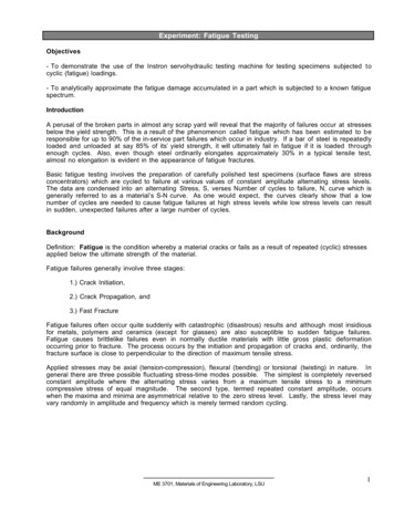
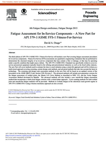
328David A. Osage / Procedia Engineering 133 (2015) 320 – 3472.6. Technical BasisThe technical basis and experimental validation of the FFS assessment procedures are summarized in Annex H ofAPI 579-1/ASME FFS-1, and are published in a series of WRC Bulletins, see references [8, 19]. The API CRE FFSCommittee is committed to publishing in the public domain the technical background to all FFS assessmentprocedures utilized in API 579-1/ASME FFS-1.3. Part 9 – Crack-Like flawsFFS assessment procedures for evaluating crack-like flaws in components are covered in API 579-1/ASME FFS1, Part 9. Assessment procedures are provided to evaluate stationary cracks and subcritical crack-growth. There isspecial emphasis in the assessment procedures in this Part for evaluating subcritical crack-growth in pressurecontaining components. There are a wide variety of process environments and material degradation mechanismsthat increase the occurrence of environmentally and service induced cracking, see API 571.3.1. FAD DiagramThe Failure Assessment Diagram (FAD) is used for the evaluation of crack-like flaws in components. The FADapproach was adopted because it provides a convenient, technically based method to provide a measure for theacceptability of a component with a crack-like flaw when the failure mechanism is measured by two distinct criteria:unstable fracture and plastic collapse. Unstable fracture usually controls failure for flaws in components when thematerial of construction is in a brittle state, i.e. low toughness, and plastic collapse typically controls failure for largeflaws if the material of construction is in a ductile state, i.e., high toughness. In a FFS analysis of crack-like flaws,the results from a stress analysis, stress intensity factor and reference stress solutions, the material strength, andfracture toughness are combined to calculate a toughness ratio, K r , and load ratio, Lr . These two quantitiesrepresent the coordinates of a point that is plotted on a two-dimensional FAD to determine acceptability. If theassessment point is on or below the FAD curve, the component is suitable for continued operation. A schematic thatillustrates the procedure for evaluating a crack-like flaw using the Failure Assessment Diagram is shown in Figure 1.3.2. Subcritical Crack-GrowthIn API 579-1/ASME FFS-1, in-service crack-growth may be categorized into five main types: crack-growth byfatigue, crack-growth by stress corrosion cracking, crack-growth by hydrogen assisted cracking, crack-growth bycorrosion fatigue and combined cyclic and time dependent crack-growth, which are shown below:dadNC 'K nFatigue(1)dadtD KmStress Corrosion, Corrosion Fatigue, Hydrogen Assisted(2)dadN³ dt dNdada(Combined Cyclic & Time-dependent )(3)Other cyclic and time dependent subcritical growth equations such as Walker, Modified Forman, NASGRO,Collipriest, ASME Section XI, and tri-linear equations may be used. An overview of these equations and applicabledata is provided in API 579-1/ASME FFS-1, Annex 9F.
David A. Osage / Procedia Engineering 133 (2015) 320 – 347Flaw DimensionsStress AnalysisStress Intensity FactorPSRSolutions, K I & K IKr329Material ToughnessK matFailureAssessm
2. Overview of the API 579-1/ASME FFS-1 Standard The first edition of API 579 Recommended Practice for Fitness-For-Service [2] published in 2000 (API 579 2000) was developed to provide guidance for conducting FFS assessments of flaws commonly encountered in the refining and petrochemical indu