Transcription
Printed Circuit BoardDesign, Prototyping, ProductionTurning Ideas Into Reality
The Company MHA-Integrated Electronic Services Ltd is a total solutions companyproviding a time critical range of design, prototype, software andproduction solutions. One of these services is the supply of prototype and medium volumebare Printed Circuit Boards (PCBs). We specialise in single anddouble sided, multilayer, flexible, flexi-rigid, HDI and buried passiverequirements. We utilise a range of UK based and offshoreapproved partners to offer a dynamic process for supplying you: Time-critical prototype Premium fast track and standard service medium volume and costsensitive higher volume PCBs We can supply product to mainland Europe within 24 hours andworld-wide within 48 hours. We offer ourselves as a long-term partner to companies who viewus as an extension of their own business who outsource engineeringand manufacturing operations to us that enable them to concentrateon their own core skills.
Quality Approvals We only use certified producers of PCB’s– Underwriters Laboratories V0 rating for FR4V0 rating for High Tg FR4V0 rating for FlexV0 rating for Flex-rigid using FR4 BS EN ISO 9001:2000 IECQ to BS 123000 (CECC) (Cert. no. 022/QCA)––––Rigid S/S, D/S, M/LFlexFlexi-rigidAll above with through, blind and buried holes (mechanically and laserdrilled) Future Quality Approvals– Underwriters Laboratories V1 approval for reinforced polyimide
Capabilities & Design Guidelines (1) Current TechnologyMaximum number of layers36Controlled ImpedanceMinimum track75µm (3mil)Vias in S/M padsMinimum gap75 µ m (3mil)Planar transformersSmallest mechanically drilled holes150 µ m (6mil)Chip on-board and component in-boardSmallest mechanically drilled blindholes150µm (6mil)Edge platingSmallest laser drilled holes25 µ m (1mil)Smallest laser drilled blind holes50 µ m (2mil)Smallest buried holes25 µ m (1mil)Aspect ratio max – through holes16:1 (FHS)Aspect ratio max – blind holes1:1 (FHS)Drilled hole edge to copper (M/L rigids)175 µ m (7mil)Drilled hole edge to copper (F/Rs)225 µ m (9mil) /- 10%Edge plated half holesEdge plated fingersBuried resistorSolder resist laser ablationResin filled viasCopper filled blind vias /- 15%
Capabilities & Design Guidelines (2) Future TechnologyMinimum track:50µm (2mil)Minimum gap:50µm (2mil)Drilled hole edge to copper150µm (6mil)Buried CapacitanceLaser structuing (copper pattern and solder resist) Maximum PCB Dimensions– More than 4 layers : 26.2” x 19.2”– 4 or less layers: 27.2” x 19.2”– Thickness 25µm to 4.8mm (6mm if sub-contractedprocess used)
Capabilities & Design Guidelines (3) PCB types––––––––––––Single sidedDouble sidedMultilayer (including sequential build)Stepped multilayerHigh Density Interconnect (HDI)FlexibleFlex-rigidControlled impedanceSurface mounted and buried heat sinksBlind and buried viasBuried resistorsFibre Optics in board
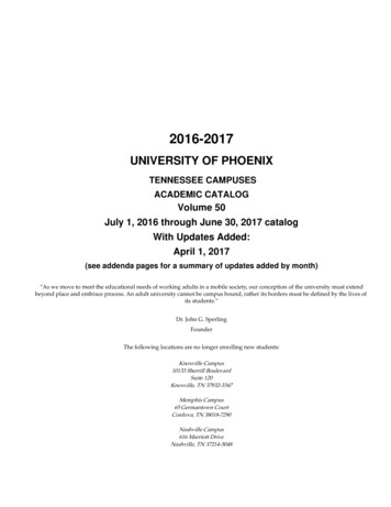
Popular Designs & Guidelines (8 layer) Standard plated through holeCopper feature to be at least0.175mm away from drilled hole (0.225mm if F/R)Track (75 micron)Layer 1Layer 2Layer 3Layer 4Layer 5Layer 6Layer 7Layer 8Pad size at least 0.2mm bigger thanDrilled hole (0.3mm if F/R)Drilled hole diameter is 0.15mm minimum(Finished Hole Size (FHS) is 0.1mm less than drilled size)Aspect ratio (thickness : FHS) is 16:1 maximumFor 1.6mm thick PCB, minimum drill size is 0.2mm
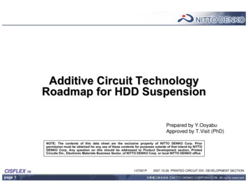
Popular Designs & Guidelines (8 layer) Laser drilled blind viasPTHLaser drilled blind microvia 1-2, 7-8Capture pad to be at least 0.2mmlarger in diameter than drilled holeTarget pads can be 0.2mmdiameter for 0.1mm holeLayer 1Layer 2Layer 3Layer 4Layer 5Layer 6Layer 7Layer 8Laser via can exit to surfacemount pads on outer layers,with very little solder loss onassemblyRecommendation between layers 1 and 2: 1x10⁶ pre-preg (0.050mm) and blind drill at 0.1mm 2x10⁶ pre-preg (0.100mm) and blind drill at 0.15mmTarget pad to be at least0.1mm larger in diameterthan drilled holeDrill diameter 0.025mm—0.2mm(FHS 0.050mm less)Aspect ration 1:1 max after plating
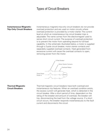
Popular Designs & Guidelines (8 layer) Buried viasPTHBuried vias 2-3, 6-7Pad size to be at least 0.2mmbigger than drilled holeLayer 1Layer 2Layer 3Layer 4Layer 5Layer 6Layer 7Layer 8Drilled hole diameter 0.025mm—0.2mm.Can be laser drilled.Aspect ratio 16:1 max
Popular Designs & Guidelines (8 layer) Laser blind sequential bondBuried PTH(resin filled)Laser drilled blind hole 1-2, 7-8as described earlierLayer 1Layer 2Layer 3Layer 4Layer 5Layer 6Layer 7Layer 8PTHs from 1-8 are optional.If not required, outer layers can contain only surface mount pads.All vias must exit to pads, so 2-7 holes must have pads on 2 and 7.
Popular Designs & Guidelines (8 layer) Blind sequential bondLayer 1Layer 2Layer 3Layer 4Layer 5Layer 6Layer 7Layer 8“Double multilayer” with blind holes filling and plating over.All vias must exit to pads, so 1-4 and 5-8 holes must have pads on 4 & 5.
Popular Designs & Guidelines (8 layer) Double laser blind sequential (2 bonds)Buried PTHLayer 1Layer 2Layer 3Layer 4Layer 5Layer 6Layer 7Layer 8Laser drilled blind holes1-2, 2-3, 6-7, 7-8
Popular Designs & Guidelines (8 layer) Double laser blind sequential (3 bonds)Buried PTHLayer 1Layer 2Layer 3Layer 4Layer 5Layer 6Layer 7Layer 8Laser drilled blind holes1-2, 2-3, 6-7, 7-8
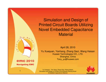
Annular Ring & Feature ClearanceTrack to Feature ClearanceCross-section after platingLayer 1Layer 2CORECORECORECORELayer 3Layer 4Minimum of 0.075mm (3mil)clearance between pad andtrackLayer 5Layer 6Clearance0.175mm (7mil)clearance overdrilled holeAnnular Ring0.10mm (4mil)annular ring overdrilled hole sizeMinimum of 0.175mm (7mil)clearance between hole and track
Solder Resist and Legend (1) Solder resist– Rigid circuits – Colour matt green. Other finishes and coloursavailable including red, black and blue.– Flexible circuits Nippon Polytech NPR-80/ID 100T (screenprinted). Colour brown.– Nominal Thickness 25µm (min 12.5µm)– We can plug through via holes using solder resist with a drill sizeof 0.3mm Legend– Photo-imagable or silkscreen– Minimum line width of 150µm (6mil)– Standard colour White or Yellow. Peel Mask– Nominal Thickness 250µm (10mil), min 200µm (8mil)
Solder Resist and Legend (2) Solder resist features:Minimum resist dam: 75 µm (3mil)Minimum resist clearance (to ensure no encroachment): 50µm (2mil)Solder resist registration: /-50µm (2mil)
Profiling Copper to Edge– 0.25mm (10mil) Rout Diameters– 0.6, 0.8, 1.6, 2.4mm standard. Others please enquire Route Tolerance– /- 0.1mm Chamfer AnglesCopper to edge of PCB:0.4mm (16mil) minimum– 20 , 45 standardResidue: 0.2mm weak, 0.3mmmedium, 0.4mm strong Scoring cut angle 30 Scoring tolerance: /- 0.1mm (4mil) Knife edge tooling for flexible circuit technology ( /-0.2mmedge to pattern). Laser profiling with 20µm "cut" ( /-25µm edgeto pattern)
Maximum Panel SizesProcessMaximum (“)AdditionalExposure21 x 24Outer layer21 x 26Inner layerPlating24 wideMachining21 x 30Drilling18 x 24RoutingBonding21 x 28Surface finish18 x 24Nickel/Gold24 x 24HASL24 wideImmersion Tin24 wideSilverPlasma desmear18 x 24Test25.6 x 26.4Silkscreen21 x 26Conveyorised24 wideFlying Probe and Bed of Nails testerDesmear, Resist, Etch, Bond Trest DirectMetalisation Usable circuit area is 1.8” less in each axis Our standard panel sizes are 12x18 12x21 16x18 16x21 18x21 18x24 21x26 (limited processes) 21x28 (limited processes)
Controlled Impedance Test Equipment– Polar CITS500 Differential Impedance Dielectric Constant– Tester 3.85 or 4.3 after bonding standard Tolerance– 10% standard– 5% tstriplineEdge-coupledsurface microstripBroadside-coupledstripline
Electrical TestMachine type:Flying probe and dedicated (bed of nails) testTest type:Double sided, simultaneous test to supplied dataPitch:100µm (4mil) minimumPad size:80µm (3mil) minimumActive test area:23.6”x24.4” maximumPanel size:25.6”x26.4” maximumBoard thickness:0.025mm – 10mm (0.001” – 0.4”)Insulation test:Pass 10MΩ standard (can test 0.5MΩ to 150MΩ)Continuity test:Pass 10Ω standard (can test 0.05Ω to 8kΩ)Test voltage:10V (can test up to 250V)
Rigid materials (1)MaterialTg( C)DkDfTCE(z)(%)Application/Comments50-260 CMultifunctional FR41353.8 – 4.60.0254.5Popular PCB material used in computer and telecommunicationapplications etc. Can also have specific CTI. Higer Tg than DifunctionalLaser drillable pre-preg1354.60.0254.5Easier to laser drill giving smoother hole wallsGetek1803.90.0123.9Improved thermal and electrical propertiesHigh Tg FR41804.60.0254.1Withstands higher temperaturesBT/Epoxy1854.10.0153.5Withstands higher temperatures. Better electrical properties - lower Dkand DfCyanate Ester2503.70.0092.5Withstands extremely high temperatures and has excellent ands extremely high temperatures due to high Tg and low TCE(z) . Low Df.PTFE Alternatives2803.43.50.0020.004Properties approaching PTFE but can be processed like FR4. Optimumfrequency range 100MHz to 15GHzPTFE2602.30.001Optimum frequency range 1-90GHz.Metal backed PTFE280Can be thick Aluminium, Brass or Copper backedSI glassResin Coated Copper(RCC)Halogen Free0.0261603.4Better signal integrityIdeal for outer layers with laser micro-drilling down to penultimatelayers, bonded to rigid core. No reinforcement.Environmentally friendly
Rigid materials (2) Higher Glass Transition Temperature (Tg) giveslower Z axis TCE, giving better reliability atextreme temperatures, better in-service repaircapability and the ability to produce thickerboards with higher aspect ratio holes enduringhigher temperatures Lower Dielectric Constant (Dk) gives increasedsignal speeds Lower Dissipation Factor (Df) minimises signalattenuation Copper from 5µm to 140µm
Flexible materials (1)MaterialManufacturerAdhesivetypeThicknessBase (mil)ThicknessAd. (mil)ThicknessCu. (µm)Copper cladextruded polyimideEspanex SB seriesAdhesiveless1,2-Du Pont AP seriesAdhesiveless1,2,3TorayAdhesivelessDu Pont LF seriesDkDfFlamabilityRating12, 18, 35,703.50.004V0-12, 18, 35,703.20.002V02-2, 40.025V0Acrylic1, 2, 3, 4, 5*118, 35, 703.70.03NoneDu Pont FNC seriesEpoxy1,2*0.818, 35, 703.70.01V0Espanex SPC seriesModifiedPolyimide11.4-803.4V0Du Pont LF0 seriesAcrylic1, 2, 3, 51,2,3-40 Adh360 base3.7NoneDu Pont FNCC seriesEpoxy11.5-V0Bond ply(ad. /base/ad.)Du Pont LF0 seriesAcrylic1, 2, 31,2,3-NoneBond ply (pureadhesive)Espanex SPB seriesModifiedPolyimide-1.4,2-Du Pont FNCA seriesEpoxy-1.6-V01 approx--V0CoverlayFlex photoimageable solderresistNippon PolytechNPR-80/ID100T* Thicknesses exclude adhesive on both sidesTg( C)40 Adh360 base1703.30.01V0
Flexible materials (2) Our preferred flex material is the Espanex range,which is manufactured by the Nippon SteelChemical company (NSC). Seewww.holders.co.uk for details. We can also use and hold reasonable stocks ofDuPont and Toray adhesiveless materials andDuPont LF-series. We hold UL rating (V0) for flex and flex-rigidsthat use Espanex flex and FR4 rigid materials. Other materials available on request. Polyester based materials can also be obtainedfor low temperature applications.
Copper Weight ConversionsOz/sqftµmmil .71351.42702.831054.241405.6Mixed copper weights are available
FinishesFinishElectroless Nickel/Immersion GoldElectroless Nickel/Electroless Palladium/Immersion Gold (“Super” or “Universal” finish)Thickness3-5 µm Ni0.1µm max Au3-5 µm Ni, 0.6 – 0.8 µmPb, 0.05-0.1µm AuTypical usesSoldering, Aluminium wire bond, Touch padsSoldering, Aluminium wire bond, Gold wire bond, Touchpads, Pogo pin contactsElectroplated Hard (Tab) Gold2.5µm pore free AuEdge friction contacts, All over friction contactsElectroplated Soft Gold2.5µm pore free AuSoldering, Aluminium wire bond, Gold wire bond, Touchpads, Pogo pin contactsHASL (63:37)15 µmElectroplated Tin/Lead Immersion TinOrganic Solderability PreservativeSoldering0.3 µmElectroless Nickel/Electroplated Hard Gold3-5 µm Ni, 0.8 µm min AuElectroless Nickel/Electroplated Soft Gold3-5 µm Ni1 µm min soft AuImmersion Sterling SilverImmersion TinSoldering0.2-0.3 µm Ag 1 µmSolderingEdge friction contacts All over friction contactsSoldering, Aluminium wire bond, Gold wire bond, Touchpads, Pogo pin contactsSoldering, Aluminium wire bond, Touch Pads.SolderingCarbon Key PadsPalladium (with or without Silver or Nickelundercoat)Mixed Finishes (enquire)4 µm pore free(1 µm if undercoated)Soldering, Aluminium wire bond
Turnaround time (working days)StandardFastDouble sided102Multilayer153 (depending on layercount)Flexible155Flexi-rigid2010Faster turnaround times are available dependant on product type
CONTACT DETAILSHead Office: MHAInt-ElectLowton Business Park, Newton Road,Newton, WA3 2AP, EnglandTelephone: 44 (0)1942 604191REG.: GB 3522631sales@mhaintelect.com
bare Printed Circuit Boards (PCBs). We specialise in single and double sided, multilayer, flexible, flexi-rigid, HDI and buried passive requirements. We utilise a range of UK based and offshore approved partners to offer a dynamic process for supplying you: Time-critical prototype Premium fast track and standard service medium volume .