Transcription
Using Oscilloscopes in Serial BusDecoding and Analysis1/9www.gwinstek.comGOOD WILL INSTRUMENT CO., LTD.
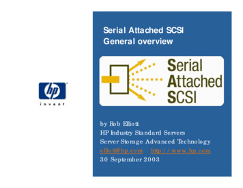
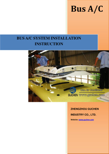
PrefaceThe communication quality of low cost, high speed transmission and high reliability is always demanded in theindustrial control applications. Currently predominant protocol generally adapts serial or parallel mode. Especially theserial protocol is widely used in embedded products. The typical integration of the serial bus includes universalasynchronous receiver transmitter bus (UART), synchronous peripheral interface (SPI) and the internal integrated circuit(I2C). The GW Instek GDS-3000 Series oscilloscope is an oscilloscope with optional serial bus analysis. Users simply setthe trigger conditions to perform the UART, I2C and SPI decoding and analysis.As shown in Fig.1, the user can use the GW Instek GDS-3000 serial bus analysis function to quickly configure andobtain measurement results.Fig. 1 Illustration for the GDS-3000 serial bus analysisFig 1 is explained as below:Start BitThe Start bit is shown as a green bracket.Stop BitThe Stop bit is shown as an orange bracket.DataData packets can be shown in Hex or Binary. The color of the packet is the same asthe channel color.Error IndicatorIf there is an error in decoding the serial data, an error indicator will be shown.2/9www.gwinstek.comGOOD WILL INSTRUMENT CO., LTD.
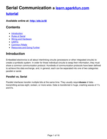
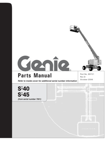
Bus IndicatorThe Bus indicator shows the bus position. The active bus is shown with a solidcolor. The Variable knob can be used to horizontally position the Bus indicatorwhen it is active.Activated bus (B1)Active bus (B1)Trigger ConfigurationShows the bus trigger (B1/B2) and the Trigger On settings.Introducing UART, I2C and SPI and related applications on oscilloscopesUARTUART, standing for the Universal Asynchronous Receiver / Transmitter short, is an asynchronous receivertransmitter. The Hardware is used to converse transmission of data between the serial communication and the parallelcommunication. UART is usually used in link with other protocols (such as EIA RS-232).UART includes interface standard specifications such as RS232, RS449, RS423, RS422 and RS485 and bus standardspecifications, which is the standard corresponding to variety of asynchronous serial communication interface standardsand bus standard. It provides the electrical characteristics, transmission rate and connection characteristics of thecommunication. Actually it belongs to the physical layer (bottom) concept of communication network. It has no directrelationship with the communication protocol. The communication diagram is shown as in figure 2. The UART test anddecoding in the GDS-3000 is shown in Figure 3 and Figure 4.Fig.2 Illustration of UART control3/9www.gwinstek.comGOOD WILL INSTRUMENT CO., LTD.
Fig. 3 Illustration of the GDS-3000 testing in UARTFig. 4 Illustration of the GDS-3000 UART decodingI2CI2C (Inter-Integrated Circuit) bus was developed by PHILIPS in the early 1980s. The original purpose for this bus is toallow the CPU chip and chip in the TV set to connect more easily. At First, it was widely used in development of theaudio and video. Now it is mainly used in server management, temperature sensing, voltage level conversion, EEPROM,general IO interface, A/D and D/A conversion, voice coding (CODEC), micro-controller. It contains the communicationof the individual components status. The administrator can query for each individual component to manage the systemconfiguration or control the functional state of each component such as power supplies and system fans. It can alwaysmonitor various parameters such as memory, hard drive, network, system temperature, etc. to increase the security ofthe system for easily management.The data rate is selectable from 7bit addressing 100kbits/s or high-speed 10bit addressing 3.4Mbits/s.4/9www.gwinstek.comGOOD WILL INSTRUMENT CO., LTD.
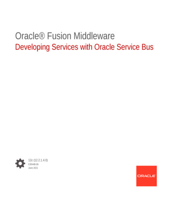
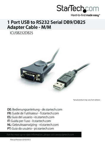
I2C’s features include:zHalf duplex bus. Only two signal cords are needed: Serial Data cord (SDA) and serial clock line (SCL)zEach connected component in the bas has an independent and unique addressing. The addressing for complexsystem is controlled by software and need not to use hardware circuit for carrying out the address decoding.zSupports multi-master bus.zCollision detection is controlled by the software.Illustration is shown as Fig. 5.Fig. 5 Illustration of I2C controlThrough the I2C decoding function of the GDS-3000, I2Csignals can be analyzed in real time. The testing illustrationand decoding result are shown in Fig. 6 and 7.Fig. 6 Illustration of the GDS-3000 testing in I2C5/9www.gwinstek.comGOOD WILL INSTRUMENT CO., LTD.
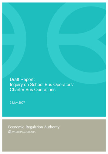
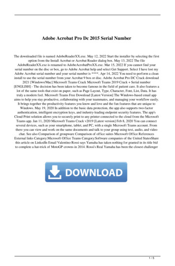
Fig. 7 Illustration of the GDS-3000 I2C decodingSPISerial peripheral interface, similar to I2C, is a 4-wire synchronous serial data protocol, which is suitable for use inportable device platform devices, but it is not as common used as I2C. Serial peripheral interface is generally in form of4-wire, but sometimes 3-wire too. Therefore, 4-channel oscilloscope is needed for completing the SPI test requirements.The full name for the standard signal are as follows:SCLK - Serial Clock (output from the control terminal)MOSI - Master Output Slave Input (output from the control side)MISO - Master Input Slave Output t (output from the terminal been controlled)SS - Slave Select (Low Level action, output from the control terminal)Users can control the SPI Slave through the SPI Master, wiring diagram is in Fig. 8. The illustration of theGDS-3000 is shown in fig. 9.Fig. 8 Illustration for SPI control6/9www.gwinstek.comGOOD WILL INSTRUMENT CO., LTD.
Fig. 9 Illustration of the GDS-3000 testing in SPIGDS-3000 also equips with SPI decoding. Its decoding and analysis result is shown as Fig. 10.Fig. 10 Illustration for the GDS-3000 SPI decodingSummaryBy using serial bus decoding and analysis function in theGW Instek GDS-3000, users can select UART, I2C and SPIdecode function easily through the buttons on the front panel.Speedy decoding and analysis capabilities can quickly reduce themeasurement time.With its diverse functionality, the GDS-3000 is the best C/Psolution for waveform analysis and decoding among 150MHz 350MHz oscilloscope.7/9www.gwinstek.comGOOD WILL INSTRUMENT CO., LTD.
GDS-3000 Series IntroductionGDS-3000 series is an innovative testing platform providing up to 350 MHz bandwidth, 4 analogue input channels,5GSa/s, and VPO technology (Visual Persistence Oscilloscope). Beside these, it also equips an innovative split screensystem with independent horizontal settings, vertical settings and triggers. This is a new function which can be used intesting, research, and manufacturing. With power analysis and serial bus analysis software, GDS-3000 series alsoenables engineers to expedite product testing, developing, and manufacturing.Features* 350/250/150MHz with 2/4 Channels* 5GSa/s RT or 100GSa/s ET Sampling Rate* Independent Memory for Each Channel* VPO Technology* Large 8-inch 800x600 Display* Split Screen Function* 3 Built-in Impedances (50Ω/75Ω/1MΩ)* Power Analysis Software (Optional)* Serial Bus Analysis Software for I2C, SPI and UART (Optional)GDS-3000 seriesChannelsBandwidthsampling 542Ch Ext4Ch Ext2Ch Ext4Ch Ext2Ch Ext4Ch ExtDC 150MHz (-3dB)2.5GSa/s5GSa/sDC 250MHz (-3dB)2.5GSa/smemorylength5GSa/sDC 350MHz (-3dB)5GSa/s5GSa/s25k pointsFor more information about product, power analysis software, and its corresponding accessories, please visitour detail.aspx?pid 3&mid 7&id 12908/9www.gwinstek.comGOOD WILL INSTRUMENT CO., LTD.
9/9www.gwinstek.comGOOD WILL INSTRUMENT CO., LTD.
UART includes interface standard specifications such as RS232, RS449, RS423, RS422 and RS485 and bus standard specifications, which is the standard corresponding to variety of asynchronous serial communication interface standards and bus standard. It provides the electrical characteristics, transmission rate and connection characteristics of the