Transcription
Power System Security:Contingency AnalysisECG 7401
Background Power System Security involves practices designed tokeep the system operating when components fail. Most power systems are operated such that any singleinitial failure event will not leave other componentsheavily overloaded. The above is referred to as the NERC (n-1) rule!, i.e., nosingle outage will result in flow or voltage violations. System security can be broken down into 3 majorfunctions: a) system monitoring – Chap. 9, b)contingency analysis, Chap. 7, c) security-constrainedOPF – Chap. 8.2
Difference between reliability and securityReliability of a power system refers to the probability ofsatisfactory operation over the long run. It denotes theability to supply adequate electric service on a nearlycontinuous basis, with few interruptions over an extendedtime period. (IEEE Paper on Terms & Definitions, 2004)Security is a time-varying attribute which can be judged bystudying the performance of the power system under aparticular set of conditions. Reliability, on the other hand, isa function of the time-average performance of the powersystem; it can only be judged by consideration of thesystem’s behavior over an appreciable period of time.3
Requirements of Reliable Electric Power Service Steady-state and transient voltages and frequency must be heldwithin close tolerances Steady-state flows must be within circuit limits Synchronous generators must be kept running in parallel withadequate capacity to meet the load demand Maintain “integrity” of bulk power network: avoid cascadingoutagesNERC, North American Electric Reliability Corporation:Mission is to ensure reliability of the bulk power system in NorthAmerica. They develop/enforce reliability standards; assessreliability annually via seasonal forecasts; monitor the bulkpower system; evaluate users, owners, and operators forpreparedness; and educate, train, and certify industrypersonnel. NERC is a self-regulated organization, subject tooversight by the U.S. Federal Energy Regulatory Commission4
5
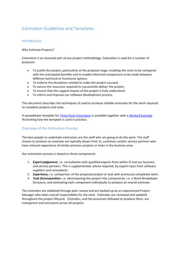
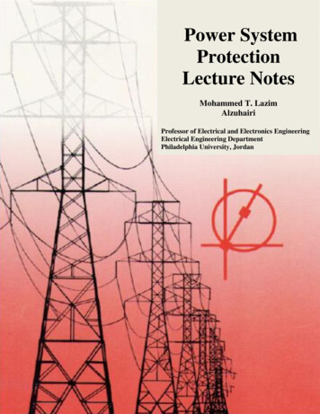
An operator’s view of out of limitsStatic security (our quencyinstabilityRotor angleinstabilityDynamic security6
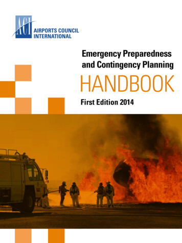
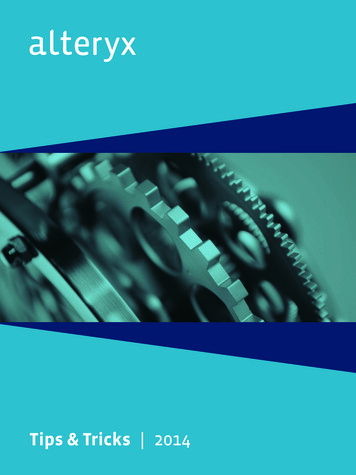
Power system operational “States” & actionsNormal (secure)Other actions(e.g. switching)Off-economicdispatchRestorativeExtreme emergency.Separation, cascadingdelivery pointinterruption,load sheddingAlert,Not secureEmergencyControlled loadcurtailment7
Power system operational “States” & actions For all credible contingencies, the system will, at worsttransit from the normal state to the alert state, rather thanto a more severe state such as the emergency state. If a system is operated according to a criteria, the systemcan transition from normal state to emergency state onlyfor a non-credible (extreme) contingency. When the alert state is entered following a contingency,operators can take actions to return the system to thenormal state, but such actions should not include loadshedding. Load shedding should only be performed underemergencies.8
Contingency Analysis(Detection of Network Problems) Generation outages: The initial imbalance will result in frequency drop whichmust be restored (Chap. 10). Other generators must make up the loss of power fromthe outaged generator – must have sufficient spinningreserve. Line flows and bus voltages will be altered – check forviolations. Transmission Outages: All flows in nearby lines and bus voltages will beaffected. The result can be line flow limit and/or voltage limitviolations. Other outages Bus outages Loss of load9
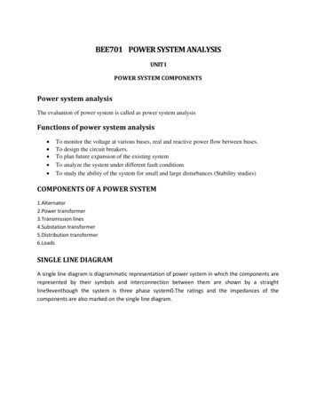
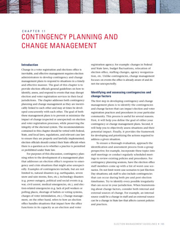
AC Power Flow ContingencyAnalysis Procedure (Fig. 7.2)10
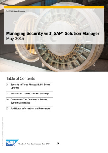
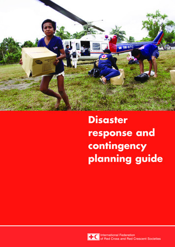
Example: Security analysis on 6-bus network usingPowerWorld Base Case: (modified V1 to 1.05pu)11
Example: Security analysis on 6-bus network usingPowerWorld Loss of Generator at Bus 2:12
Example: Security analysis on 6-bus network usingPowerWorld Loss of line 3-6:13
Example: Security analysis on 6-bus network usingPowerWorld Increase load at bus 4 by 50%:14
“DC” power flow in parallel paths300 MWBus 2x23 .2y23 5x12 .1y12 10900 MWBus 1x13 .4y13 2.5Bus 3Let Sbase 1000 MVA[B]1200MW[X] [B]-115
“DC” power flow in parallel pathsTreat power injections as currents sources and use superposition.(a) 900 MW source acting alone:Bus 2514.3514.3x23 .2x12 .1x13 .4900 MWBus 1900 MW385.7Bus 316
“DC” power flow in parallel paths(b) 300 MW source acting alone:300 MWBus 285.7x23 .2x12 .1214.3x13 .4Bus 185.7Bus 3300 MW17
“DC” power flow in parallel paths(c) Use Superposition300 MWBus 2Total 728.6Total 428.6900 MWTotal 471.4Bus 1Bus 31200 MW18
Generator loss @ Bus 2Using Current Division:Bus 2685.7685.7x23 .2x12 .11200 MWx13 .4Bus 1514.3Bus 31200MW19
Quick but Approximate Line Flows Using LinearSensitivity factorsIf one of the buses happens to be a reference bus, set thecorresponding X elements in the equation above to zero.20
Generator loss @ Bus 2Bus 2685.7685.7x23 .2x12 .11200 MWx13 .4Bus 1514.3Bus 31200MWLine 2-3: l321
Quick but Approximate Line Flows Using LinearSensitivity factors22
Line loss300 MWBus 2Lose line 2-3300900 MW1200Bus 1Bus 31200 MW23
Assignment: See PowerWorld video on contingency training/contingency-analysis Then conduct a full contingency analysis usingPowerWorld on the 6-bus power system you modeled inChapter 6.24
Example: Security analysis on 6-bus network using PowerWorld Loss of Generator at Bus 2: 12 . Example: Security analysis on 6-bus network using PowerWorld Loss of line 3-6: 13 . Example: Security analysis on 6-bus network using PowerWorld Increase load at bus 4 by 50%: 14 . 15 "DC" power flow in parallel paths