Transcription
H12SST-PSUSER’S MANUALRevision 1.0
The information in this User’s Manual has been carefully reviewed and is believed to be accurate. The vendor assumesno responsibility for any inaccuracies that may be contained in this document, and makes no commitment to updateor to keep current the information in this manual, or to notify any person or organization of the updates. Please Note:For the most up-to-date version of this manual, please see our website at www.supermicro.com.Super Micro Computer, Inc. ("Supermicro") reserves the right to make changes to the product described in this manualat any time and without notice. This product, including software and documentation, is the property of Supermicro and/or its licensors, and is supplied only under a license. Any use or reproduction of this product is not allowed, exceptas expressly permitted by the terms of said license.IN NO EVENT WILL Super Micro Computer, Inc. BE LIABLE FOR DIRECT, INDIRECT, SPECIAL, INCIDENTAL,SPECULATIVE OR CONSEQUENTIAL DAMAGES ARISING FROM THE USE OR INABILITY TO USE THIS PRODUCTOR DOCUMENTATION, EVEN IF ADVISED OF THE POSSIBILITY OF SUCH DAMAGES. IN PARTICULAR, SUPERMICRO COMPUTER, INC. SHALL NOT HAVE LIABILITY FOR ANY HARDWARE, SOFTWARE, OR DATA STOREDOR USED WITH THE PRODUCT, INCLUDING THE COSTS OF REPAIRING, REPLACING, INTEGRATING,INSTALLING OR RECOVERING SUCH HARDWARE, SOFTWARE, OR DATA.Any disputes arising between manufacturer and customer shall be governed by the laws of Santa Clara County in theState of California, USA. The State of California, County of Santa Clara shall be the exclusive venue for the resolutionof any such disputes. Supermicro's total liability for all claims will not exceed the price paid for the hardware product.FCC Statement: This equipment has been tested and found to comply with the limits for a Class A digital devicepursuant to Part 15 of the FCC Rules. These limits are designed to provide reasonable protection against harmfulinterference when the equipment is operated in a commercial environment. This equipment generates, uses, and canradiate radio frequency energy and, if not installed and used in accordance with the manufacturer’s instruction manual,may cause harmful interference with radio communications. Operation of this equipment in a residential area is likelyto cause harmful interference, in which case you will be required to correct the interference at your own expense.California Best Management Practices Regulations for Perchlorate Materials: This Perchlorate warning applies onlyto products containing CR (Manganese Dioxide) Lithium coin cells. “Perchlorate Material-special handling may apply.See ING: Handling of lead solder materials used in this product may expose you to lead, achemical known to the State of California to cause birth defects and other reproductive harm.The products sold by Supermicro are not intended for and will not be used in life support systems, medical equipment,nuclear facilities or systems, aircraft, aircraft devices, aircraft/emergency communication devices or other criticalsystems whose failure to perform be reasonably expected to result in significant injury or loss of life or catastrophicproperty damage. Accordingly, Supermicro disclaims any and all liability, and should buyer use or sell such productsfor use in such ultra-hazardous applications, it does so entirely at its own risk. Furthermore, buyer agrees to fullyindemnify, defend and hold Supermicro harmless for and against any and all claims, demands, actions, litigation, andproceedings of any kind arising out of or related to such ultra-hazardous use or sale.Manual Revision 1.0Release Date: August 22, 2019Unless you request and receive written permission from Super Micro Computer, Inc., you may not copy any part of thisdocument. Information in this document is subject to change without notice. Other products and companies referredto herein are trademarks or registered trademarks of their respective companies or mark holders.Copyright 2019 by Super Micro Computer, Inc.All rights reserved.Printed in the United States of America
PrefacePrefaceAbout This ManualThis manual is written for system integrators, IT technicians and knowledgeable end users.It provides information for the installation and use of the H12SST-PS motherboard.About This MotherboardBuilt upon the functionality and capability of the AMD EPYC 7002 series processor, theH12SST-PS motherboard provides superior graphics capability and system performancewhile consuming little power. Please note that this motherboard is intended to be installedand serviced by professional technicians only. For processor/memory updates, please referto our website at http://www.supermicro.com/products/.Conventions Used in the ManualSpecial attention should be given to the following symbols for proper installation and to preventdamage done to the components or injury to yourself:Warning! Indicates important information given to prevent equipment/property damageor personal injury.Warning! Indicates high voltage may be encountered when performing a procedure.3
H12SST-PS User's ManualContacting SupermicroHeadquartersAddress:Super Micro Computer, Inc.980 Rock Ave.San Jose, CA 95131 U.S.A.Tel: 1 (408) 503-8000Fax: 1 (408) 503-8008Email:marketing@supermicro.com (General Information)support@supermicro.com (Technical per Micro Computer B.V.Het Sterrenbeeld 28, 5215 ML's-Hertogenbosch, The NetherlandsTel: 31 (0) 73-6400390Fax: 31 (0) 73-6416525Email:sales@supermicro.nl (General Information)support@supermicro.nl (Technical Support)rma@supermicro.nl (Customer ss:Super Micro Computer, Inc.3F, No. 150, Jian 1st Rd.Zhonghe Dist., New Taipei City 235Taiwan (R.O.C)Tel: 886-(2) 8226-3990Fax: 886-(2) w.supermicro.com.tw4
PrefaceTable of ContentsChapter 1 Introduction1.1 Quick Reference.11Quick Reference Table.13Motherboard Features.141.2 Processor and Chipset Overview.171.3 Special Features.17Recovery from AC Power Loss.171.4 System Health Monitoring.18Onboard Voltage Monitors.18Fan Status Monitor with Firmware Control.18Environmental Temperature Control.18System Resource Alert.181.5 ACPI Features.191.6 Power Supply.191.7 Super I/O.19Chapter 2 Installation2.1 Static-Sensitive Devices.20Precautions.20Unpacking.202.2 Motherboard Installation.21Location of Mounting Holes.21Installing the Motherboard.232.3 Processor and Heatsink Installation.242.4 Memory Support and Installation.31Memory Support.31DIMM Module Population.32DIMM Installation.33DIMM Removal.332.5 Rear I/O Ports.342.6 Front Control Panel.352.7 Connectors.365
H12SST-PS User's Manual2.8 Jumper Settings.39How Jumpers Work.392.9 LED Indicators.412.10 PCI-E 4.0 Slots.43Chapter 3 Troubleshooting3.1 Troubleshooting Procedures.44Before Power On.44No Power.44No Video.45System Boot Failure.45Memory Errors.45When the System Loses its Setup Configuration.45When the System Becomes Unstable.463.2 Technical Support Procedures.473.3 Frequently Asked Questions.473.4 Returning Merchandise for Service.493.5 Battery Removal and Installation.50Battery Removal and Installation.50Chapter 4 UEFI BIOS4.1 Introduction.51Starting the Setup Utility.514.2 Main Setup.524.3 Advanced.544.4 IPMI.694.5 Event Logs.724.6 Security.744.7 Boot.754.8 Save & Exit.77Appendix A SoftwareA.1 OS Installation.79Installing the Windows OS for a RAID System.79Installing Windows to a Non-RAID System.79A.2 Driver Installation.806
PrefaceA.3 SuperDoctor 5.81A.4 IPMI.82Appendix B Standardized Warning StatementsB.1 Battery Handling.83B.2 Product Disposal.85Appendix C UEFI BIOS RecoveryC.1 Overview.86C.2 Recovering the UEFI BIOS Image.86C.3 Recovering the BIOS Block with a USB Device.867
H12SST-PS User's ManualChapter 1IntroductionCongratulations on purchasing your computer motherboard from an industry leader. Supermicroboards are designed to provide you with the highest standards in quality and performance.In addition to the motherboard, several important parts that are included with the system arelisted below. If anything listed is damaged or missing, please contact your retailer.Important LinksFor your system to work properly, please follow the links below to download all necessarydrivers/utilities and the user’s manual for your server. Supermicro product manuals: http://www.supermicro.com/support/manuals/ Product drivers and utilities: https://www.supermicro.com/wftp/driver/AMD/SP3 Product safety info: http://www.supermicro.com/about/policies/safety information.cfm If you have any questions, please contact our support team at: support@supermicro.comThis manual may be periodically updated without notice. Please check the Supermicro websitefor possible updates to the manual revision level.8
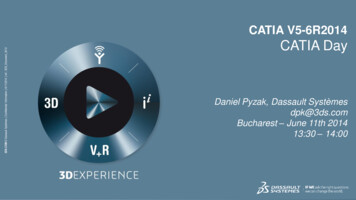
Chapter 1: IntroductionFigure 1-1. H12SST-PS Motherboard ImageNote: All graphics shown in this manual were based upon the latest PCB revision availableat the time of publication of the manual. The motherboard you received may or may not lookexactly the same as the graphics shown in this manual.9
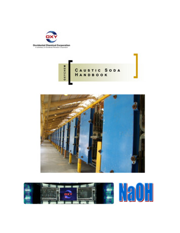
H12SST-PS User's ManualPWROK1 2 3JVGA1 FAN3BMCLED1 UID LED2VGA2IPMI LANJLAN11COM1JUIDB1UID SW89FB1 JCOM1JUSB1MH1USB1/2(3.0)MH2SXB3A1B1BMCJCPLD1CPU SLOT1 PCI-E 4.0 X161JSIOM1SIOM:CPU PCI-E 4.0 X16 X1NCSISXB4 CPU SLOT2 PCI-E 4.0 X16H12SST-PSMH4REV:1.00DESIGNED IN USAUM5UM7BMCIPMI SD1/2:SATA DOM ATA7BIOS LICENSECPUJTPM1SXB2CPU PCI-E 4.0 X16SXB1MH7SATA0 5M.2-HC4 SATA34 37CPU PCI-E 4.0X4M.2-HC1 SATA20 23CPU PCI-E 4.0X4SATA24 27CPU PCI-E 4.0X4M.2-HC2M.2-HC3 SATA30 33R41875 R4201ACLED8ACLED5R425AC AR429AC ALED6R428LED77426874274JUSBA1CPU PCI-E 4.0 X8USB3(2.0)JVRM1JDBG21-2:NORMAL MODE2-3:DEBUG MODEJUART1 FR2JRST1 JPFR1JPWR1JPFR3BAR CODEMH8CMOS CLEARBATTERY4FAN41FAN4MH23JF1MH25Figure 1-2. H12SST-PS Motherboard Layout10
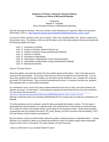
Chapter 1: Introduction1.1 Quick ReferenceCOM1PWROKPWROKVGA2IPMI LANCOM1JUIDB1UID SW81JLAN1UID SW9FB1 JCOM1JUSB1MH1USB1/2(3.0)FAN3USB 1/2 (3.0)BMCLED1 UID LED2JVGA1 FAN31 2 3IPMI LANBMC LED1UID LED2VGAMH2SXB3A1B1BMCJCPLD1CPU SLOT1 PCI-E 4.0 X16SXB3NCSI1SIOMJSIOM1SIOM:CPU PCI-E 4.0 X16 X1NCSIREV:1.00DESIGNED IN USAUM5UM7BMCIPMI CODEBIOSBIOS D1/2:SATA DOM ATA7SATA7SATA6SXB4SXB4 CPU SLOT2 PCI-E 4.0 M1CPUCPU PCI-E 4.0 X16DIMMA1DIMMB1DIMMC1DIMMD1SXB2SXB2SXB1MH7SATA0 5SXB1M.2-HC4 SATA34 37CPU PCI-E 4.0X4M.2-HC1 SATA20 23CPU PCI-E 4.0X4SATA24 27CPU PCI-E 4.0X4M.2-HC2M.2-HC3 SATA30 33R41875 R4201ACA6874274JUSBA1USB3(2.0)JVRM1JUART1 ST1 JPFR1JPWR1JPFR3BAR CODEMH8CMOS CLEARJDBG1Battery (BT1)JDBG21-2:NORMAL MODE2-3:DEBUG 2511LED8ACLED5R425C AR429AC ALED6R428LED72M.2-HC4 M.2-HC3 M.2-HC2CPU PCI-E 4.0 X8USB3 (2.0)74M.2-HC1
H12SST-PS User's ManualNotes: See Chapter 2 for detailed information on jumpers and I/O ports. Jumpers/LED indicators not indicated are used for testing only. Use only the correct type of onboard CMOS battery as specified by the manufacturer. Toavoid possible explosion, do not install the battery upside down.12
Chapter 1: IntroductionQuick Reference TableJumperDescriptionDefault SettingUID SWUnit ID switch (push-button toggle switch ON/OFF)OffJBT1Clear CMOSOpen (Normal)JDBG1Debug mode controlPins 1-2: Normal modeJWD1Watch Dog controlPins 1-2: ResetLEDDescriptionStatusUID LED2Rear unit ID LEDSolid blue: UID switched to ON, unit identifiedBMC LED1BMC Heartbeat LEDGreen: Blinking (BMC normal), Green: Fast blinking (BMC initializing)PWROKPower OK LEDGreen: System power OKConnectorDescriptionBattery (BT1)Onboard CMOS batteryCOM 1Front panel COM port #1FAN 3/4System fan headersIPMI LANDedicated IPMI LAN portJF1Front control panelJTPM1Trusted Platform Module (TPM)/Port 80 connectorSIOMPCI-E 4.0 x16 x1 slot for proprietary add-on moduleSXB1PCI-E 4.0 x8 slot and SATA 0 5SXB2PCI-E 4.0 x16 slotSXB3PCI-E 4.0 x16 left hand riser slotSXB4PCI-E 4.0 x16 right hand riser slotM.2 HC1-4M.2 connector PCI-E 4.0 x4 and SATA connectionNCSINCSI headerUSB 1/2 (3.0)Back panel USB 3.0 portsUSB 3 (2.0)Internal USB 2.0 portVGABack panel VGA portNote: Jumpers, connectors, switches, and LED indicators that are not described in thepreceding tables are for manufacturing testing purposes only, and are not covered in thismanual.13
H12SST-PS User's ManualMotherboard FeaturesFeaturesCPU Single AMD EPYC 7002 series processors, SoC, in SP3 socketsMemory Up to 2 TB of ECC DDR4 3200MHz speed, RDIMM/LRDIMM/3DS/NVDIMM memory in eight slotsDIMM Size Up to 256GB size at 1.2VChipset System on ChipExpansion Slots Two PCI-E 4.0 x16 on Riser Cards (SXB3, SXB4)One PCI-E 4.0 x8 and SATA 0 5 (SXB1)One PCI-E 4.0 x16 (SXB2)One PCI-E 4.0 x16 x1 Slot for Proprietary Add-on Module (SIOM)M.2 Interface: 4 SATA/PCI-E 4.0 x4M.2 Form Factor: 2242, 2260, 2280, 22110M.2 Key: M-KeyNetwork ATEN IPMI from ASPEED AST 2500 BMC for gigabit RJ45 portGraphics ASPEED AST2500 BMC chip with one VGA portI/O Devices Six SATA 3.0 ports (via SXB1)Two SATA DOMOne SIOM (PCI-E 4.0 x16 x1) networking slotOne COM connectorFour SATA port via M.2 SlotPeripheral Devices Two USB 3.1 “Type A” ports on the rear I/O panel (USB 1/2)One USB 2.0 internal "Type A" connection (USB 3)Note: The table above is continued on the next page.14
Chapter 1: IntroductionFeaturesBIOS 256Mb SPI AMI BIOS ACPI 6.2, SMBIOS 3.1.1, Plug-and-Play (PnP), RTC (Real Time Clock) wake up, Riser Card Auto-Detection SupportPower Management ACPI power management (S5)Power button override mechanismPower-on mode for AC power recoverySystem Health Monitoring Onboard voltage monitoring for 3.3V, 5V, 12V, 3.3V Standby, 5V Standby, VBAT, Vcore, Vsoc, and memoryOnboard monitoring for CPU, system, and memory temperatureCPU switching phase voltage regulatorCPU Thermal Trip supportFan Control Single cooling zoneLow-noise fan speed controlPulse Width Modulation (PWM) fan controlSystem Management Trusted Platform Module (TPM) supportSystem resource alert via SuperDoctor 5SuperDoctor 5, Watch DogNon-Maskable Interrupt (NMI)SUM-InBand, SUM-OOB, IPMICFG, IPMIVIew, SMCIPMITOOLLED Indicators Power State IndicatorCPU/OverheatingFan FailureLAN activityUID / Remote UIDDimensions 18.86" (L) x 6.8." (W) (479.04 mm x 172.72 mm)15
H12SST-PS User's ManualFigure 1-3.System Block DiagramNote: This is a general block diagram and may not exactly represent the features on yourmotherboard. See the previous pages for the actual specifications of your motherboard.16
Chapter 1: Introduction1.2 Processor and Chipset OverviewThe H12SST-PS motherboard offers maximum I/O expandability, energy efficiency, and datareliability in a 7-nm process architecture, and is optimized for high performance computing,and ideal for High Density Data Center applications.The H12SST-PS supports the new microarchitecture 7-nm process technology, whichdrastically increases system performance for a multitude of server applications.The AMD EPYC 7002 series processor supports the following features: ACPI Power Management Logic Support Rev. 6.2 Adaptive Thermal Management/Monitoring PCI-E 4.0 w/transfer rates of up to 16 Gb/s SATA 3.0 w/transfer rates of up to 6 Gb/s System Management Bus (SMBus) Specification Version 2.01.3 Special FeaturesThis section describes the health monitoring features of the H12SST-PS motherboard. Themotherboard has an onboard System Hardware Monitor chip that supports system healthmonitoring.Recovery from AC Power LossThe Basic I/O System (BIOS) provides a setting that determines how the system will respondwhen AC power is lost and then restored to the system. You can choose for the system toremain powered off (in which case you must press the power switch to turn it back on), orfor it to automatically return to the power-on state. See the Advanced BIOS Setup sectionfor this setting. The default setting is Last State.17
H12SST-PS User's Manual1.4 System Health MonitoringThis section describes the health monitoring features of the H12SST-PS motherboard. Themotherboard has an onboard Baseboard Management Controller (BMC) chip that supportssystem health monitoring. Once a voltage becomes unstable, a warning is given or an errormessage is sent to the screen. The user can adjust the voltage thresholds to define thesensitivity of the voltage monitor.Onboard Voltage MonitorsThe onboard voltage monitor will continuously scan crucial voltage levels. Once a voltagebecomes unstable, it will give a warning or send an error message to the screen. Users canadjust the voltage thresholds to define the sensitivity of the voltage monitor. Real time readingsof these voltage levels are all displayed in BMC.Fan Status Monitor with Firmware ControlUsers can check the RPM status of the cooling fans through the IPMI Web interface. Thechassis fans are controlled by Thermal Management.Environmental Temperature ControlThe thermal control sensor monitors the CPU temperature in real time and will turn on thethermal control fan whenever the CPU temperature exceeds a user-defined threshold. Theoverheat circuitry runs independently from the CPU. Once the thermal sensor detects thatthe CPU temperature is too high, it will automatically turn on the thermal fans to prevent theCPU from overheating. The onboard chassis thermal circuitry can monitor the overall systemtemperature and alert the user when the chassis temperature is too high.Note: To avoid possible system overheating, please be sure to provide adequate airflow toyour system.System Resource AlertThis feature is available when used with SuperDoctor 5 . SuperDoctor 5 is used to notify theuser of certain system events. For example, you can configure SuperDoctor 5 to provide youwith warnings when the system temperature, CPU temperatures, voltages and fan speedsgo beyond a predefined range.18
Chapter 1: Introduction1.5 ACPI FeaturesACPI stands for Advanced Configuration and Power Interface. The ACPI specification definesa flexible and abstract hardware interface that provides a standard way to integrate powermanagement features throughout a computer system including its hardware, operating systemand application software. This enables the system to automatically turn on and off peripheralssuch as network cards, hard disk drives and printers.In addition to enabling operating system-directed power management, ACPI also provides ageneric system event mechanism for Plug and Play and an operating system-independentinterface for configuration control. ACPI leverages the Plug and Play BIOS data structureswhile providing a processor architecture-independent implementation that is compatible withWindows 2016 and Windows 2019 operating systems.1.6 Power SupplyAs with all computer products, a stable power source is necessary for proper and reliableoperation. It is even more important for processors that have high CPU clock rates. In areaswhere noisy power transmission is present, you may choose to install a line filter to shieldthe computer from noise. It is recommended that you also install a power surge protector tohelp avoid problems caused by power surges.1.7 Super I/OThe ASpeed AST2500 Super I/O provides one high-speed, 16550 compatible UniversalAsynchronous Receiver/Transmitter (UART), which support serial infrared communications.This UART includes a send/receive FIFO, a programmable baud rate generator, completemodem control capability and a processor interrupt system. This UART provides legacy speedwith baud rate of up to 115.2 Kbps as well as an advanced speed with baud rates of 250 K,500 K, or 1 Mb/s, which support higher speed modems.The Super I/O provides functions that comply with ACPI (Advanced Configuration and PowerInterface), which includes support of legacy and ACPI power management through the SystemManagement Interrupt (SMI) or System Control Interrupt (SCI). It also features auto powermanagement to reduce power consumption.19
H12SST-PS User's ManualChapter 2Installation2.1 Static-Sensitive DevicesElectrostatic Discharge (ESD) can damage electronic com ponents. To prevent damage to yourmotherboard, it is important to handle it very carefully. The following measures are generallysufficient to protect your equipment from ESD.Precautions Use a grounded wrist strap designed to prevent static discharge. Touch a grounded metal object before removing the board from the antistatic bag. Handle the board by its edges only; do not touch its components, peripheral chips, memorymodules or gold contacts. When handling chips or modules, avoid touching their pins. Put the motherboard and peripherals back into their antistatic bags when not in use. For grounding purposes, make sure that your chassis provides excellent conductivity between the power supply, the case, the mounting fasteners and the motherboard. Use only the correct type of CMOS onboard battery as specified by the manufacturer. Donot install the CMOS battery upside down, which may result in a possible explosion.UnpackingThe motherboard is shipped in antistatic packaging to avoid static damage. When unpackingthe motherboard, make sure that the person handling it is static protected.20
Chapter 2: Installation2.2 Motherboard InstallationAll motherboards have standard mounting holes to fit different types of chassis. Make surethat the locations of all the mounting holes for both the motherboard and the chassis match.Although a chassis may have both plastic and metal mounting fasteners, metal ones arehighly recommended because they ground the motherboard to the chassis. Make sure thatthe metal standoffs click in or are screwed in tightly.PhillipsScrewdriver (1)Phillips ScrewsStandoffs (11)Only if NeededTools NeededLocation of Mounting HolesNotes:1. To avoid damaging the motherboard and its components, please do not use a forcegreater than 8 lb/inch on each mounting screw during motherboard installation.2. Some components are very close to the mounting holes. Please take precautionarymeasures to avoid damaging these components when installing the motherboard to thechassis.21
H12SST-PS User's ManualFigure 2-1. Motherboard Mounting Holes22
Chapter 2: InstallationInstalling the Motherboard1. Install the I/O shield into the back of the chassis.2. Locate the mounting holes on the motherboard. See the previous page for the locations.3. Locate the matching mounting holes on the chassis. Align the mounting holes on themotherboard with the mounting holes on the chassis.4. Install standoffs in the chassis as needed.5. Install the motherboard into the chassis carefully to avoid damaging other motherboardco
support@supermicro.com (Technical Support) Website: www.supermicro.com Europe Address: Super Micro Computer B.V. Het Sterrenbeeld 28, 5215 ML 's-Hertogenbosch, The Netherlands Tel: 31 (0) 73-6400390 Fax: 31 (0) 73-6416525 Email: sales@supermicro.nl (General Information) support@supermicro.nl (Technical Support) rma@supermicro.nl (Customer .