Transcription
Telecommunications Grounding andBonding GenericChandrashekarTechnical Manager (India & SW Asia)9/10/2014
Purpose and scope of TIA-607-BTIA-607-B grounding is normativeand applies to entire building, notjust data centerScope nowincludesgrounding ofITETIA-607-B, “GenericTelecommunicationsBonding andGrounding (Earthing)for CustomerPremises”, is nowapproved!
Scope of TIA‐607‐BWhat is TIA-607-B?Scope: Specifies requirements for ageneric telecommunications bondingand grounding infrastructure, and itsinterconnection to other systems, forlocations where telecommunicationsequipment will be or are installedMajor revision of J‐STD‐607‐A: Includes G&B of telecommunicationsspaces (distributors and computerrooms) Continued harmonization efforts (aspracticable) on terminology andpractices with international standardsDistributorsComputerRoomsTGBTMGBTBB
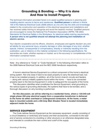
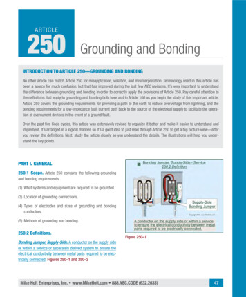
Equipment in Cabinets and RacksTIA-607-B:“Rather than relyingon the ac power cordground wire, it isdesirable thatequipment begrounded in a verifiablemanner as described inthis Standard.”Figure 7—Example of three methods to bondequipment and racks to ground
Telecommunications Bonding Backbone (TBB) Purpose of TBB is to reducepotential differences betweeninterconnectedtelecommunications systems ondifferent floors Originates at TMGB and extendsthroughout building usingtelecom pathways Connects TGBs that exist in eachdistributor
6TIA-607-B TBB sizing
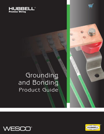
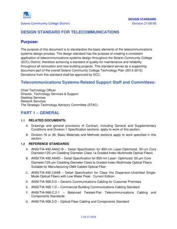
Conductor sizing isn’t only about electrical issues Standards call for a minimum #6AWG for mechanical strengthSize matters!Source: Picture from Internet
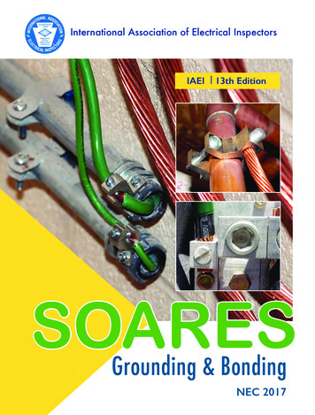
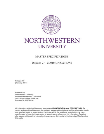
Supplemental bonding grid construction per TIA-607-B #6 AWG round wire or 2”wide copper strips bondedat intersections Minimum grid density is 3m (10 ft) centers Minimum 1/0 bond toTGB/TMGBExample supplemental bonding grid
Example SBG constructionMake aisle groundsconvenient to racksand cabinetsCross aisle groundsevery 10 feet Use #6 AWG wire Use pedestalgrounding clamps atconductorintersections Bond to AC powerground through alocal TGB
TEBC to rack connector – TIA-607-BOnly 2-hole mechanical is allowed for thisapplication. Concerns:(1) Vibration test was done at one amplitude andfrequency, which is different from what datainstallations experience(2) No consideration for temperature fluctuation(3) No consideration for stress relaxation
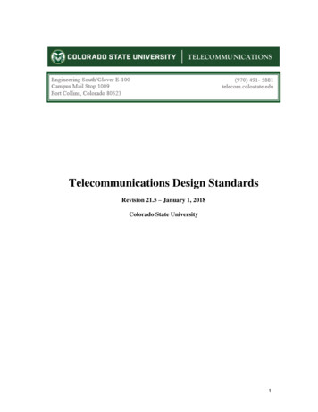
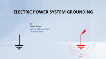
Mesh-BN: a collection of components (As per CENELEC documents, includesTIA-942’s Data Center Grounding Infrastructure as the “SupplementalBonding Network” and IEEE Std 1100 calls the MCBN), per TIA-607-BBuilding steelConduitsCablingpathways(not shown)Informationtechnologyequipment (ITE)Racks andcabinetsSupplementalbonding grid(SBG)Rack bondingconductor(RBC)
12Preventing loose busbar connectionsBICSI-607 stainless steel TGB hardwarestack-up (requires locking washer, andstainless or SiBr hardware)(Parts HDW1/4-KT, HDW3/8-KT)Two-holecompressionlugs requiredon TGB &TMGB(Type LCC-W)
13BICSI Telecommunications Distributions Methods Manual(12th) on the TGB and TMGB The sameconsiderations as arefound in TIA-607-B
14ANSI/NECA/BICSI-607-2011 busbarsPanduitrecommendationon busbar holepatterns: pick apattern and stickwith it. It’sconfusing to havemultiple holepatterns later.Recommend usingthe BICSI/TIA holepattern, as it is welldefined and knownin industry.
What else needs to be bonded? IEEE studies have indicated that the point of diminishing financialreturns with respect to lightning strikes is 2 meters (6 feet) Bond anything that could become charged that a person couldbump while working on a rack/cabinet for safety Therefore, bond any conductive path within six feet of yourracks/cabinets
Bond cable tray and ladder rack sectionsSplit bolts – use tin plated ifoutdoors (SBC & SBCT,respectively)#6 AWG conductor,green w/yellow jacket– OR –Specify systems thatautomatically bond toreduce chances of errorWyr-Grid and GRIDRUNNERhardware automatically bondssections, eliminating the need forjumper wires
17Remote zone enclosures and TIA-607-BTIA‐607‐B“Distributors” need TGB/TMGBReferences TIA‐568‐C.0 for definitionTIA‐568‐C.0, 4.4 Distributors“Distributors provide a location for administration, reconfiguration, connection ofequipment, and for testing. Distributors can be configured as interconnections or cross‐connections ”Figure 3 of the same document shows distributors starting at “Active equipment”My conclusion If it has active equipment, then it needs groundingSizing the conductor A TBB, per TIA‐607‐B, originates at the TMGB. It bonds TGBs to the TMGB (5.2.4) A TEBC connects racks to the TMGB/TGB (7.1) TGB is located “as close as practicable to the panelboard” “The TEBC shall be a continuous copper conductor that is sized not less than a No. 6AWG or as the largest size equipment grounding conductor in he ac branch powercircuit(s) serving the racks/cabinet lineup.
Panduit grounding research Panduit research over the last two years has found the presence of phase imbalance onthe telecommunications grounding system in the steady‐state Frequencies are powerline and the first couple of harmonicsObservations: High buildingsteel currents UPSs are at endof line-up creatingpower imbalancein the groundconductor No noticednetworkdegradation on thepart of networkoperators
Episodic/transient researchCRACPanelRack bonding conductorAH Systems BCP‐512 Probe(high bandwidth)Tektronix TPS 2024 7 MHz transient measured on ACEG at CRAH, but not detectable at closest rack Conclusion so far: mesh bonding and separate circuits from the AC panel are effectivemeans of mitigating issues with transients Flat braids have not been shown to offer a tangible benefit for this application19
20Grounding rules of thumb for optimum surge suppression“Optimum performance of surge protectors is achieved at five Ohms or below. Severalmanufacturers of electronic equipment also require five to ten Ohms as a maximumresistance for their gear to work correctly.”‐ Ditek “Technical White Paper: Grounding 101”
21TIA-607-B-1 - External Grounding* TR 42.16voted to adopt as normative on June 6, 2012Two categoriesof facility:1. Minimum requirements: maintain 25Ω throughout year, recommends at least twoelectrodes2. Enhanced requirements for critical facilities: designed to have 10Ω or less (and“preferably 5Ω or less”)–––––Public safety facilitiesMilitary installationsData centersWeb hosting facilitiesCentral offices“Where telecommunications equipment is distributed throughout a structure andmay be interconnected by metallic links, the minimally required grounding systemmay not be adequate. Facilities with advanced requirements or distributedequipment will benefit from the addition of a building perimeter ground loop.”
22Design specifications, per TIA-607-B-1 Commission a soil resistivity study– The most common method of measuring average soil resistivity is the four‐point method– Require a series of readings in different locations to get a better idea of the soil conditions Require measurements of the ground system resistance as verification of the design– 3‐pole fall‐of‐potential method (if room is available, and the ground is not connected to thepower system)– Clamp‐on meter
23TIA-607-B-1 potential equalization design highlights
Summary
Standards call for a minimum #6 AWG for mechanical strength Source: Picture from Internet. Supplemental bonding grid construction per TIA-607-B . TIA-942's Data Center Grounding Infrastructure as the "Supplemental Bonding Network" and IEEE Std 1100 calls the MCBN), per TIA-607-B