Transcription
APCAPPLICATION NOTE #156StruxureWare Data Center Expert v7.2.0Building Management System IntegrationBy Kevin KoskoAbstractBuilding Management Systems (BMS) are implemented in a building's infrastructure to collect data of assorted manageddevices that comprise this infrastructure. Some examples of the devices that the BMS would monitor could includegenerators, computer room air conditioners (CRAC), uninterruptible power supply (UPS), power distribution units (PDU), firesensors, or building switchgear. The BMS itself is typically a stand-alone computer that contains a software program used tocollect data and a hardware interface used to connect it to the monitored devices. This software program is designedspecifically for each application, as each building infrastructure is unique and the monitoring points may be different for eachdevice. A master-slave type system exists between the BMS and the connected devices. There is one node (the master nodeor BMS) that requests data from one of the "slave" nodes (connected devices) and then translates the responses into readabledata. Slave nodes will not typically transmit data without a request from the master node, and do not communicate with otherslaves.Modbus ProtocolThe Modbus protocol is a standard in the buildings industry and is supported by many BMS vendors. Modbus is an applicationlayer messaging protocol, which provides client/server communication between devices connected on different types of busesor networks, typically within a building's infrastructure. There are a few different types of the Modbus protocols, which includeModbus TCP (TCP/IP binary), Modbus (serial ASCII), and Modbus RTU (serial binary). For the discussion in this applicationnote, StruxureWare Data Center Expert uses the Modbus TCP protocol. Modbus TCP communication is becoming morecommon in the industry, because Modbus TCP/IP simply takes the Modbus instruction set and wraps TCP/IP around it.Implementation costs are exceptionally low and minimum hardware is required, which is why the industry is more and moreadopting Modbus TCP as a standard.Schneider Electric integrates Modbus TCP over an Ethernet connection for StruxureWare Data Center Expert'scommunication with a BMS (e.g. TAC Andover Continuum and TAC Vista , Johnson Controls’ Metasys , Siemens’APOGEE , ALC’s WebCTRL , etc.). This paper explains the integration of the Schneider Electric StruxureWare DataCenter Expert v7.2.0 server appliance with a Building Management System.Note: APC and TAC are subsidiaries of Schneider Electric and have tested and integrated StruxureWare DataCenter Expert’s Modbus TCP with T.A.C. Andover Continuum and Vista . The integration of these managementsystems provides the ability to correlate the physical infrastructure of the data center “white space” with thesupporting building infrastructure.1 2012 Schneider Electric. All rights reserved. The trademark InfraStruxure is owned by Schneider Electric Industries S.A.S., American Power ConversionCorporation, or their affiliated companies. All other trademarks are the property of their respective owners. Rev 2012-3
APCAPPLICATION NOTECommunication InterfaceStruxureWare Data Center Expert uses a RJ-45 Ethernet interface. The RJ-45 Ethernet interface allows for longer cablelengths and faster transmission of data compared to traditional RS-232 or RS-485 data transmission. RS-232 and RS-485 canbe as slow as a baud rate of 2400, have limited communication distance between devices and the BMS, and only supportpoint-to-point connections. By converting the communication to RJ-45, data transmission increases greatly, with the potentialof transferring at 1GB port speeds if your network permits.Modbus TCP communication between the BMS and StruxureWare Data Center Expert occurs on TCP port 502 as an industrystandard.Note: Any data transmission or discovery errors could be a result of incorrect communication settings on the BMS orport 502 not being an open port for data transmission.Communication between StruxureWare Data Center Expert and the BMSAs stated previously, StruxureWare Data Center Expert is connected to the BMS through a RJ-45 port (GB1) located on theserver appliance. StruxureWare Data Center Expert monitors the connected devices on the Public LAN or on the APC LAN,which is a private Ethernet connection. This allows for only one connection between the BMS and StruxureWare Data CenterExpert, instead of multiple connections to each monitored device. StruxureWare Data Center Expert then becomes thegateway for all information the BMS would request. When the BMS add-on module is enabled in StruxureWare Data CenterExpert (this is done with an additional purchased license key), each device on the public and private network is added to a listof devices available for Modbus monitoring. As devices are added to StruxureWare Data Center Expert, the user has theability to add devices, to be monitored up to a maximum of 247. The devices are assigned a slave address (1-247), whichserves as a unique identifier for the individual data points of each device. The BMS would then be configured to add anEthernet gateway (this terminology may vary per BMS vendor) connecting through TCP port 502 in order to discoverStruxureWare Data Center Expert. After the configured device register maps in StruxureWare Data Center Expert have beenimported into the BMS, the BMS can then request data from each of these devices as if it were connected directly to them.2 2012 Schneider Electric. All rights reserved. The trademark InfraStruxure is owned by Schneider Electric Industries S.A.S., American Power ConversionCorporation, or their affiliated companies. All other trademarks are the property of their respective owners. Rev 2012-3
APCAPPLICATION NOTEIn the current integration of StruxureWare Data Center Expert and BMS systems, there is support for Modbus Function Code04 (Read Input Registers) The communication between a BMS and connected devices, involves Read Input Registers,Queries, and Responses. These are explained below:Read Input RegistersReads the binary contents of input registers (3X references) in the slave. Broadcast is not supported. Themaximum parameters supported by various controller models are listed below.QueryThe query message specifies the starting register and quantity of registers to be read. Registers areaddressed starting at zero- registers 1 . 16 are addressed as 0 . 15.3 2012 Schneider Electric. All rights reserved. The trademark InfraStruxure is owned by Schneider Electric Industries S.A.S., American Power ConversionCorporation, or their affiliated companies. All other trademarks are the property of their respective owners. Rev 2012-3
APCAPPLICATION NOTEHere is an example of a request to read register 31000 from slave device 17:Field NameExample (Hex)Slave Address11Function04Starting Address Hi00Starting Address Lo08Number of Points Hi00Number of Points Lo01Error Check (LRC or CRC)--ResponseThe register data in the response message are packed as two bytes per register, with the binary contentsright justified within each byte. For each register, the first byte contains the high-order bits and the secondcontains the low-order bits. The response is returned when the data is completely assembled.Here is an example of a response to the query above:Field NameExample (Hex)Slave Address11Function04Byte Count02Data Hi (Register 30009)00Data Lo (Register 30009)0AError Check (LRC or CRC)--The contents of register 31009 are shown as the two byte values of 00 0A hex, or 10 decimal.Floating point numbersModbus registers contain 16 bits of data. Because Modbus registers do not handle floating point numbers the float isconverted to an integer by multiplying it by 10, 100 or 1000 (depending on the number of decimal places) to preserve theprecision. Thus, in some of the valid responses there will be a note indicating that the response must be divided by 10, 100 or1000 to yield the correct results.4 2012 Schneider Electric. All rights reserved. The trademark InfraStruxure is owned by Schneider Electric Industries S.A.S., American Power ConversionCorporation, or their affiliated companies. All other trademarks are the property of their respective owners. Rev 2012-3
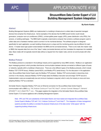
APCAPPLICATION NOTEStruxureWare Data Center Expert Data RegistersStruxureWare Data Center Expert allows the user the flexibility to configure the data registers for each device. The registerrange spans from 31000 – 39999 and the amount of Modbus registers vary per device. First you will select the device youwould like to read data from, chose the Slave address and then generate the register map (Figure 1). Once the register mapis created it can then be exported and imported into the BMS (Figure2).Figure 15 2012 Schneider Electric. All rights reserved. The trademark InfraStruxure is owned by Schneider Electric Industries S.A.S., American Power ConversionCorporation, or their affiliated companies. All other trademarks are the property of their respective owners. Rev 2012-3
APCAPPLICATION NOTEFigure 2StruxureWare Data Center Expert Device Alarm Count RegisterThe device alarm count register will always remain 30999 and will display the maximum number of device alarms per devicethat are active within StruxureWare Data Center Expert. Devices that have unmapped register values will return 0xDEAD asseen below.RegisterDescriptionModbusRegisterRegister Value(s)Active Alarm Count0x309990-MaxMagic Values0xDEADRegister Value DescriptionActive Alarm CountValue refers to an empty or unmappedregister6 2012 Schneider Electric. All rights reserved. The trademark InfraStruxure is owned by Schneider Electric Industries S.A.S., American Power ConversionCorporation, or their affiliated companies. All other trademarks are the property of their respective owners. Rev 2012-3
APCAPPLICATION NOTEStruxureWare Data Center Expert Device Status RegisterThe device status register is common to all discovered devices. The Modbus register for the device status will always remainat 30998 with the register value changing. Below are the following register values for device status:RegisterDescriptionDevice Status D0xFFFE0xFFFFDevice discovery phase is in progressNo Status is available for deviceOk onal stateDevice is in warning stateDevice is in error stateDevice is in critical stateDevice is in failure stateDevice is in maintenance modeRegister Value DescriptionStruxureWare Data Center Expert Device Alarm CodesIn the following table are the Alarm codes common to all devices. Each alarm will have two registers per alarm with theregisters starting prior to 30998 and based on the number of alarms, you would need to poll two registers for each alarm. Forexample: If there are 10 devices sensors in an alarm state each with one alarm, you would need to poll 20 registers prior30998, in order to display the alarm code and the sensor code for the device it corresponds to.RegisterDescriptionEach alarm spans tworegisters with the firstregister representingthe alarm code andthe secondrepresenting thecorresponding sensor.ModbusRegisterRegisterValue(s)0x30998 – (maxalarms reported) vice alarmExclude (test) alarmDevice info alarmCommunication lostThreshold violation: too lowThreshold violation: too low too longThreshold violation: too highThreshold violation: too high too longThreshold violation: increase too fastThreshold violation: decrease too fastThreshold violation: state changeDDF Download FailureCapture drive failureRemote link failedLog on errorGeneral Device Alarm0x?Specific device alarms (see each device alarmtable for the Modbus register value andregister value description)Alarms are read as a negative offset fromthe Device Status Register (0x30998) up toMax alarms reported. Alarms are provided inorder of severity. A single alarm occupiestwo registersRegister Value Description7 2012 Schneider Electric. All rights reserved. The trademark InfraStruxure is owned by Schneider Electric Industries S.A.S., American Power ConversionCorporation, or their affiliated companies. All other trademarks are the property of their respective owners. Rev 2012-3
APCAPPLICATION NOTEStruxureWare Data Center Expert Corresponding Device Sensor CodesIn the following table are the corresponding sensor codes paired with the alarm codes above.Register Value(s)0xFFFF0xFFFESensor register #Register Value DescriptionSensor association unknown.Sensor association known but sensornot mapped to a register.Address of the register mapped to thealarming sensorEnvironmental Management System Device Alarm Codes (EMS)The following table contains Modbus alarm codes specific to the EMS.RegisterValue(s)Register Value DescriptionRegister Value Description0x1A230x1903Sensor disconnectedMaximum temperature thresholdviolationDiscrete input abnormal state with'informational' severityMaximum analog input thresholdviolation0x1A25High analog input threshold violation0x1905High temperature threshold violation0x1A270x19070x1A290x1909Low temperature threshold violationMinimum temperature thresholdviolationLow analog input threshold violationMinimum analog input thresholdviolation0x1A2CBeacon disconnected0x190BMaximum humidity threshold violation0x1A2DBeacon on0x190DHigh humidity threshold violation0x1A31Relay output abnormal state0x031A0x1902Lost communication with themanagement interfaceRegisterValue(s)0x1A210x190FLow humidity threshold violation0x1A33Switched outlet abnormal state0x1911Minimum humidity threshold violation0x1A35Current limit exceeded0x1913Short-term increasing temperature rateof change violation0x1B02Lost communication0x1915Short-term decreasing temperaturerate of change violation0x1B04Sensor disconnected0x1917Long-term increasing temperature rateof change violation0x1B05Maximum temperature thresholdviolation0x1919Long-term decreasing temperature rateof change violation0x1B07High temperature threshold violation0x1A02Lost communication0x1B090x1A04Sensor disconnected0x1B0BLow temperature threshold violationMinimum temperature thresholdviolation8 2012 Schneider Electric. All rights reserved. The trademark InfraStruxure is owned by Schneider Electric Industries S.A.S., American Power ConversionCorporation, or their affiliated companies. All other trademarks are the property of their respective owners. Rev 2012-3
APCRegisterValue(s)APPLICATION NOTERegister Value DescriptionRegisterValue(s)Register Value Description0x1A05Maximum temperature thresholdviolation0x1B0DMaximum humidity threshold violation0x1A07High temperature threshold violation0x1B0FHigh humidity threshold violation0x1A090x1B11Low humidity threshold violation0x1A0BLow temperature threshold violationMinimum temperature thresholdviolation0x1B13Minimum humidity threshold violation0x1A0DMaximum humidity threshold violation0x1B15Short-term increasing temperaturerate of change violation0x1A0FHigh humidity threshold violation0x1B17Short-term decreasing temperaturerate of change violation0x1A11Low humidity threshold violation0x1B19Long-term increasing temperature rateof change violation0x1A13Minimum humidity threshold violation0x1B1BLong-term decreasing temperaturerate of change violation0x1A15Short-term increasing temperature rateof change violation0x1B1DDiscrete input abnormal state with'critical' severity0x1A17Short-term decreasing temperaturerate of change violation0x1B1FDiscrete input abnormal state with'warning' severity0x1A19Long-term increasing temperature rateof change violation0x1B21Discrete input abnormal state with'informational' severity0x1A1BLong-term decreasing temperature rateof change violation0x1B24Beacon disconnected0x1A1DDiscrete input abnormal state with'critical' severity0x1B25Beacon on0x1A1FDiscrete input abnormal state with'warning' severity9 2012 Schneider Electric. All rights reserved. The trademark InfraStruxure is owned by Schneider Electric Industries S.A.S., American Power ConversionCorporation, or their affiliated companies. All other trademarks are the property of their respective owners. Rev 2012-3
APCAPPLICATION NOTEEnvironmental Monitoring Unit Device Alarm Codes (EMU)The following table contains Modbus alarm codes specific to the EMU.RegisterValue(s)0x031ARegister ValueDescription0x0343Lost CommunicationCritical fault on integratedEnvironmental Monitor inputcontactWarning fault on integratedEnvironmental Monitor inputcontact0x0349Lost communication to theintegrated EnvironmentalMonitor input contact0x0323A high humidity thresholdviolation exists for integratedEnvironmental Monitor Sensor0x032BA maximum humidity thresholdviolation exists for integratedEnvironmental Monitor Sensor0x0347Lost Communication0x031BRegisterValue(s)Register ValueDescription0x0327A minimum temperaturethreshold violation exists forintegrated Environmental MonitorSensorA low temperature thresholdviolation exists for integratedEnvironmental Monitor SensorA high temperature thresholdviolation exists for integratedEnvironmental Monitor SensorA maximum temperaturethreshold violation exists forintegrated Environmental MonitorSensor0x032DA minimum humidity thresholdviolation exists for integratedEnvironmental Monitor Sensor0x0321A low humidity threshold violationexists for integratedEnvironmental Monitor Sensor0x03290x031D0x031FNetwork Air FM Device Alarm CodesThe following table contains Modbus alarm codes specific to the Network Air FM.RegisterValue(s)Register ValueDescriptionRegisterValue(s)Register ValueDescription0x1303Module power on0x13B9VFD 1 fault tolerance exceeded0x13050x13070x1309Water detectedFire detectedSmoke detected0x13BB0x13BD0x13BF0x130DHead pressure high0x13C10x130FCondensate pump failed0x13C30x1311Air block interlock open0x13C5VFD 2 fault tolerance exceededCooling coil: No fluid flowCondenser: No fluid flowLost communication withexpansion module 1Lost communication withexpansion module 2Lost communication withexpansion module 310 2012 Schneider Electric. All rights reserved. The trademark InfraStruxure is owned by Schneider Electric Industries S.A.S., American Power ConversionCorporation, or their affiliated companies. All other trademarks are the property of their respective owners. Rev 2012-3
APCRegisterValue(s)APPLICATION NOTERegister ValueDescriptionRegisterValue(s)Register ValueDescription0x131BEnvironmental temperaturehighEnvironmental temperaturelow0x131D0x131FEnvironmental humidity highEnvironmental humidity low0x13CB0x13CDCoil fluid inlet temperature highCoil fluid inlet temperature low0x1325Suction pressure high0x13CFHot water inlet temperature high0x1327Suction pressure low0x13D1Hot water inlet temperature low0x132DSupply temperature high0x13D30x132FSupply temperature lowHumidifier water conductivityhighHumidifier excessive foamHumidifier current highHumidifier without powerHumidifier internal memoryerrorHumidifier water level lowHumidifier water levelreduction excessiveHumidifier drain malfunctionHumidifier cylinder full whenunit offHumidifier replace cylinderAir flow lowCoil fluid valve actuator failedCondenser valve actuatorfailed0x13D5Economizer isolator valve activeCoil fluid inlet temperaturesensor failed0x13D70x13D90x13DB0x13DDReturn sensor failedSupply sensor failedModule enabledInput #1 asserted0x13DF0x13E1Input #2 assertedInput #3 asserted0x13E30x13E5Input #4 assertedInput #5 asserted0x13E70x13E90x13EB0x13EDInput #6 assertedInput #7 assertedInput #8 assertedInput #9 asserted0x13EFInput #10 asserted0x13F1Input #11 asserted0x13F3Input #12 asserted0x13F5Input #13 asserted0x13F7Input #14 asserted0x13F9Input #15 13510x13530x13550x1357Hot water valve actuator failedVFD 1 accelerationovercurrentVFD 2 accelerationovercurrentVFD 1 decelerationovercurrentVFD 2 decelerationovercurrent0x13C7VFD 1 maintenance required0x13C9VFD 2 maintenance required11 2012 Schneider Electric. All rights reserved. The trademark InfraStruxure is owned by Schneider Electric Industries S.A.S., American Power ConversionCorporation, or their affiliated companies. All other trademarks are the property of their respective owners. Rev 2012-3
APCRegisterValue(s)APPLICATION NOTERegister ValueDescriptionRegisterValue(s)0x135FVFD 1 steady operationovercurrentVFD 2 steady operationovercurrentVFD 1 steady operationovervoltageVFD 2 steady operationovervoltage0x1361VFD 1 DC undervoltage0x14050x1363VFD 2 DC undervoltageVFD 1 power supply openphaseVFD 2 power supply x137B0x137D0x137F0x13810x13830x13850x1387VFD 1 output wiring errorVFD 2 output wiring errorVFD 1 heat sink temperaturehighVFD 2 heat sink temperaturehighVFD 1 motor 1 overloadVFD 2 motor 1 overloadVFD 1 overloadVFD 2 overloadVFD 1 accelerationovervoltageVFD 2 accelerationovervoltageVFD 1 decelerationovervoltageVFD 2 decelerationovervoltageVFD 1 external thermalsensor temperature highVFD 2 external thermalsensor temperature highVFD 1 braking resistoroverheatedVFD 2 braking resistortemperature high0x13FBRegister ValueDescription0x140D0x140FInput #16 assertedRemote sensor at address 3removedRemote sensor at address 4removedRemote sensor at address 5removedRemote sensor at address 6removedRemote sensor at address 7removedRemote sensor at address 8removedRemote sensor at address 9removedRemote sensor at address 10removedRemote sensor added0x1411Primary sensors failed0x14130x14150x14170x14190x141BSecondary Sensors failedSecondary sensors activeSystem is offlineSystem failureBackup system online0x141DSystem power off0x141FSystem is load sharing0x1421Backup system unavailable0x1423System smoke detected0x1425System fire detected0x1427Group fatal smoke alarm0x1429Group fatal fire alarm0x142BSystem communication lost0x13FD0x13FF0x14030x14090x140B12 2012 Schneider Electric. All rights reserved. The trademark InfraStruxure is owned by Schneider Electric Industries S.A.S., American Power ConversionCorporation, or their affiliated companies. All other trademarks are the property of their respective owners. Rev 2012-3
3A30x13A50x13A70x13A90x13AB0x13ADAPPLICATION NOTERegister ValueDescriptionVFD 1 motor 2 overloadVFD 2 motor 2 overloadVFD 1 memory errorVFD 2 memory errorVFD 1 keypad transmissionerrorVFD 2 keypad transmissionerrorVFD 1 CPU errorVFD 2 CPU errorVFD 1 option communicationerrorVFD 2 option communicationerrorVFD 1 option errorVFD 2 option errorVFD 1 drive startup errorVFD 2 drive startup errorVFD 1 RS485 communicationerrorVFD 2 RS485 communicationerrorAir filter cloggedCompressor 1 maintenancerequiredCompressor 2 maintenancerequired0x13AFHeater maintenance required0x13B1Humidifier maintenancerequired0x13B30x13B5Blower 1 maintenancerequiredBlower 2 maintenancerequiredRegisterValue(s)Register ValueDescription0x142D0x142F0x14310x1433Group configuration invalidGroup configuration conflictModule firmware mismatchSystem firmware mismatch0x1435Module download failure0x14370x14390x143BVFD 1 mains failureVFD 2 mains failureVFD 1 overvoltage0x143DVFD 2 overvoltage0x143F0x14410x14430x14450x1447VFD 1 inverter overloadVFD 2 inverter overloadVFD 1 motor failureVFD 2 motor failureVFD 1 power card fail0x1449VFD 2 power card fail0x14AF0x14B1Mains A failureMains B failure0x14B3Humidifier RS-485 failure0x14B5Persistent low suction pressure0x14FBThe NMC firmware is older thanthe corresponding devicefirmware0x14FD0x14FF0x13B7The NMC firmware is newerthan the corresponding devicefirmwareThe StruxureWare Data CenterExpert server is still able tocommunicate with the NMC, butthe NMC cannot communicatewith the deviceHumidifier fault toleranceexceeded13 2012 Schneider Electric. All rights reserved. The trademark InfraStruxure is owned by Schneider Electric Industries S.A.S., American Power ConversionCorporation, or their affiliated companies. All other trademarks are the property of their respective owners. Rev 2012-3
APCAPPLICATION NOTEIn Row SC Device Alarm CodesThe following table contains Modbus alarm codes specific to the In Row 3240x23260x23280x232A0x232C0x232ERegister ValueDescriptionAn internal communicationfault existsAn a-link isolation relay faultexistsAn external communicationfault existsA cooling failure existsA rack inlet high temperatureviolation existsAn air filter clogged fault 380x233ARegister ValueDescriptionA fan power supply left faultexistsA fan power supply right faultexistsAn air filter run hours violationexistsA condenser fan 1 fault existsA return air sensor fault existsA condenser inlet air sensorfault existsA supply air sensor fault existsA condenser outlet air sensorfault existsA rack inlet temperaturesensor fault existsA high discharge pressurealarm existsA low suction pressure alarmexists.An evaporator fan 1 faultexists.An evaporator fan 2 faultexists.An evaporator fan 3 faultexists.0x233CA water detection fault exists.A condensate pump faultexists.A condensate pan full faultexists.0x2354A condenser fan 2 fault existsA condenser fan 3 fault existsA supply air high temperatureviolation existsA return air high temperatureviolation existsA filter sensor fault existsA suction temperature sensorfault existsA suction pressure sensor faultexistsA discharge pressure sensorfault existsOn standby an input contact faultexists.A persistent high dischargepressure alarm exists.A persistent low suction pressurealarm exists.A startup low suction pressurealarm exists.A startup line pressureimbalance alarm exists.0x2356Lost group 0x234E0x23500x235214 2012 Schneider Electric. All rights reserved. The trademark InfraStruxure is owned by Schneider Electric Industries S.A.S., American Power ConversionCorporation, or their affiliated companies. All other trademarks are the property of their respective owners. Rev 2012-3
APCAPPLICATION NOTEIn Row RP Device Alarm CodesThe following table contains Modbus alarm codes specific to the In Row ter ValueDescriptionAn internal communicationfault exists.An A-link isolation relay faultexists.An external communicationfault exists.A cooling failure exists.A rack inlet high temperatureviolation exists.An air filter clogged faultexists.An upper return air sensor faultexists.A lower return air sensor faultexists.An upper supply air sensorfault exists.A middle supply air sensorfault exists.A lower supply air sensor faultexists.A rack inlet temperaturesensor fault exists.A condensor fluid actuator faultexists.A high discharge pressurealarm exists.A low suction pressure alarmexists.An evaporator fan 1 faultexists.An evaporator fan 2 faultexists.An evaporator fan 3 faultexists.An evaporator fan 4 faultexists.An evaporator fan 5 faultexists.An evaporator fan 6 x2C3C0x2C3E0x2C400x2C42Register ValueDescriptionA suction temperature sensorfault exists.A suction pressure sensor faultexists.A discharge pressure sensorfault exists.On standby an input contact faultexists.A persistent high dischargepressure alarm exists.A persistent low suction pressurealarm exists.An outside heat exchanger faultexists.A factory configuration notcompleted alarm exists.A liquid refrigerant sensor faultexists.An excessive compressorcycling alarm exists.A no backup units availablealarm exists.A condensate pump fault exists.A condensate pan full faultexists.An upper fan power supply faultexists.A lower fan power supply faultexists.An air filter run hours violationexists.0x2C46Lost group communication.A supply air high temperatureviolation exists.A return air high temperatureviolation exists.0x2C480x2C36A filter sensor fault exists.A water detection fault exists.0x2C4415 2012 Schneider Electric. All rights reserved. The trademark InfraStruxure is owned by Schneider Electric Industries S.A.S., American Power ConversionCorporation, or their affiliated companies. All other trademarks are the property of their respective owners. Rev 2012-3
PPLICATION NOTERegister ValueDescriptionexists.Internal communication faultexists.An A-link isolation relay faultexists.External communication faultexists.Cooling failure exists.Rack inlet 1 high temperatureviolation exists.RegisterValue(s)0x1F5EHumidifier communication faultexists.Compressor run hours violationexists.Heater 1 run hours violationexists.Heater 2 run hours violationexists.Heater 3 run hours violationexists.0x1F60Humidifier run hours 180x1F1ARack inlet 2 high temperatureviolation exists.Rack inlet 3 high temperatureviolation exists.High humidity violation exists.Low humidity violation exists.0x1F620x1F640x1F660x1F1CAir filter clogged fault exists.0x1F680x1F1E0x1F6A0x1F2EReturn air sensor fault exists.Supply air upper sensor faultexists.Rack inlet temperature sensor1 fault exists.Rack inlet temperature sensor2 fault exists.Rack inlet temperature sensor3 fault exists.Coil fluid valve actuator faultexists.High discharge pressure alarmexists.Low suction pressure faultalarm exists.High suction pressure faultalarm exists.0x1F30Frequent Humidifier faults.0x1F800x1F320x1F340x1F360x1F38Fan 1 fault exists.Fan 2 fault exists.Fan 3 fault exists.Water detection fault exists.0x1F820x1F840x1F860x1F880x1F3ACondensate pump fault x1F2A
Communication between StruxureWare Data Center Expert and the BMS . As stated previously, StruxureWare Data Center Expert is connected to the BMS through a RJ-45 port (GB1) located on the server appliance. StruxureWare Data Center Expert monitors the connected devices on the Public LAN or on the APC LAN, which is a private Ethernet connection.