Transcription
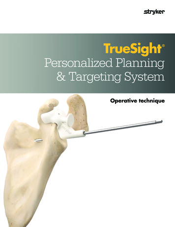
TrueSightPersonalized Planning& Targeting System Operative technique
2
TrueSight personalized planning & targeting system Operative techniqueTrueSightPersonalized Planning & Targeting SystemContentsIntroduction. . . . . . . . . . . . . . . . . . . . . . . . . . . . . . 3Indications and contraindications . . . . . . . . . .4Design rationale . . . . . . . . . . . . . . . . . . . . . . . . . . 5Bone model. . . . . . . . . . . . . . . . . . . . . . . . . . . . . . . 6TrueSight guide . . . . . . . . . . . . . . . . . . . . . . . . . . . 7Glenoid preparation . . . . . . . . . . . . . . . . . . . . . . . 8TrueSight guide placement. . . . . . . . . . . . . . . . . . 9Reverse pilot wire placement. . . . . . . . . . . . . . . 11Total pilot wire placement. . . . . . . . . . . . . . . . . 12IntroductionThis brochure is presented to demonstrate asurgical technique. The manufacturer of thisdevice does not practice medicine and cannotrecommend this or any other surgical techniquefor use on a specific patient. The choice of theappropriate surgical technique is the responsibilityof the surgeon performing the operation.Caution: Federal law in the USA restrictsthis device to sale by or on the order of aphysician.See package insert (Instruction for Use)(TRU-IFO-1) for a complete list of potentialadverse effects, contraindications, warningsand precautions. The surgeon must discuss allrelevant risks including the finite lifetime ofthe device with the patient when necessary.3
TrueSight personalized planning & targeting system Operative techniqueIndications and contraindicationsIndicationsContraindicationsThe TrueSight system is indicated for use as asurgical instrument to assist in the intraoperativepositioning of glenoid components used with totaland reverse shoulder arthroplasty by referencinganatomical landmarks of the shoulder that areidentifiable on preoperative CT- imaging scans.The TrueSight system is contraindicated in patientswith conditions or diseases that affect bonylandmark recognition.The TrueSight system can be used in conjunctionwith Stryker’s following total and reverse shoulderimplant systems and their respective compatiblecomponents: ReUnion TSA Total ShoulderArthroplasty System (K183039), ReUnion RSAReverse Shoulder System (K183039).The TrueSight Guide is single use only.4Any active infection of the surgical area where thesurgery will be performed is a contraindication forthe TrueSight system.The SurgiCase shoulder planner may restrict use forthe TrueSight system when placement of the pilotwire is not optimal for implant placement.To ensure safety and effectiveness of the TrueSightsystem guides, the SurgiCase shoulder plannerrestricts the placement of the pilot wire withinthe intersection of two cones – a 45 cone from theneutral axis and a 60 cone from the normal of theglenoid face.
TrueSight personalized planning & targeting system Operative techniqueDesignrationaleTrueSight design rationaleThe TrueSight system guide is anergonomically designed, glenoidpositioning guide made ofpolyamide that is customized toyour patient’s anatomy based onpreoperative computerizedtomography (CT) scans.The TrueSight system isdesigned to allow you to takeyour patient’s existingpreoperative CT scans, identifyspecific anatomical landmarks,and create a detailed preoperative plan using Stryker’sReUnion total and reverseshoulder implants.The software and guide aredesigned to allow for accurateimplant placement and mayimprove alignment and surgicaloutcomes.Figure 15
TrueSight personalized planning & targeting system Operative techniqueBone (glenoid)modelThe bone model is a 3Dreproduction of your patient’sglenoid. This 3D model isintended to be used as areference tool for implantplacement in conjunction withthe TrueSight guide.The bone model will be markedwith a unique patient identifier,is made of polyamide, and willbe provided non-sterile.TrueSight RSA bone modelTrueSight TSA bone modelYour patient’s TrueSight RSAbone model is provided withtwo separate entry holes. Thefirst hole is for a 1.5mm k-wirethat is intended to help stabilizethe guide when in use and thesecond hole represents the entryhole for the 3.2mm pilot wire.Your patient’s TrueSight TSAbone model is provided withthree separate entry holes. Thefirst hole is for a 1.5mm k-wirethat is intended to help stabilizethe guide when in use and thetwo additional holes representthe entry holes for the 3.2mmpilot wire.1.5mm k-wire entry hole:Aligns with the 1.5mm k-wirehole on the TrueSight guide.TSA onlyCenter 3.2mm pilotwire entry hole:Aligns with center 3.2mmpilot wire cylinder on theTrueSight guide for pilotwire placement.Superior 3.2mmpilot wire entry hole:Aligns with the superior pilotwire cylinder on the TrueSight guide for TSA superiorhole marking.Figure 26
TrueSight personalized planning & targeting system Operative techniqueThe TrueSightguideThe TrueSight guide is createdbased off your pre-operativeplan and will have severalfeatures designed to facilitatethe surgical procedure.The guide will be marked witha unique patient identifier, ismade of polyamide, and will beprovided non-sterile.TrueSight RSA guideTrueSight TSA guideThe TrueSight RSA guide will beprovided with one 1.5mm k-wireentry hole, one 3.2mm pilot wirecylinder, a push/directionalhandle, a coracoid clip, and a2mm labrum offset.The TSA TrueSight Guide guidewill be provided with one1.5mm k-wire entry hole, two3.2mm pilot wire cylinders, apush/directional handle, acoracoid clip, and a 2mmlabrum offset.TrueSight RSA guide1.5mm k-wire hole:A feature to allow the guide to beaffixed to the glenoid using a 1.5mmk-wire for additional stability.Figure 3Push or directional handle:Offers haptic or “sensorial touch”feedback and stability when seatingthe guideCoracoid clip:A feature on the guidedesigned to bepositioned aroundthe base of thecoracoid in orderto ensure properalignment of the guide.2mm labrum offset:Bridges between thecoracoid clip and the lateralbody of the guide designedto prevent soft tissueinterference at the anterosuperior border of theglenoid surface.Center 3.2mm pilot wirecylinder:A feature intended to allowfor accurate placement of the3.2mm pilot wire per yourpre-operative plan.Patient specific guide identifier:A unique alphanumeric identifierspecific to your patient.TrueSight TSA guide onlySuperior 3.2mm pilot wirecylinder:A feature intended to allow foraccurate marking of the superiorperipheral hole to allow executionof planned glenoid rotation. withthe 3.2mm pilot wire per your preoperative plan.7
TrueSight personalized planning & targeting system Operative techniqueGlenoidpreparationThe TrueSight guide wasdesigned to use the base andneck of the coracoid process asan anatomic reference for properplacement of the guide onto yourpatient’s glenoid.Prepare the anatomy bycompletely exposing the glenoidface; performing the necessarysoft tissue dissection to gaincomplete visualization of theglenoid and to ensure optimalguide positioning andplacement.NoteEach guide is designed andmanufactured to fit securelyat the base and neck of thepatient’s coracoid process.8Upon completion of adequateglenoid exposure, prepare thescapula to receive the TrueSightguide by removing all soft tissuearound the neck and lateral faceof the coracoid and obtaininghemostasis.NoteSince the guide fits aroundthe coracoid and anteriorglenoid face, adjustretractors to ensure directcontact with coracoid. Placean anterior glenoid retractorat the lower half of theglenoid so as to not interferewith the access to thecoracoid.Compare the fit and position ofthe guide on the bone model tothe planned fit and position onyour patient’s glenoid.CautionDo not remove osteophytesor alter the glenoid bonyanatomy before securingthe guide.CautionDo not damage the bonysurface where the guide is incontact with your patient’sglenoid anatomy. Do notremove cartilage.
TrueSight personalized planning & targeting system Operative techniqueTrueSight guideplacementThe following applies toboth TSA and RSA TrueSightguides unless otherwisestated.Secure the guide onto yourpatient’s glenoid by seating thecoracoid clip onto the base ofcoracoid and verify that thepilot wire cylinder is fullycontacting or seated on theglenoid face (Figure 4).Check for gaps between theTrueSight guide and the glenoidanatomy to ensure a proper fit(Figure 5).CautionDo not alter the guide beforeuse. Doing so could generatedebris which couldcontaminate the operatingregion. In addition, alteringthe guide could compromiseits fit to the patient’s glenoidanatomy.Figure 4Apply and maintain axialpressure on the directional/pushhandle of the guide to keepcontact between the guide andunderlying glenoid during pilotwire placement (Figure 6).CautionAvoid excessive inferiorpushing of the guide. Makesure critical anatomicstructures are not damagedduring the guide attachment.Figure 59
TrueSight personalized planning & targeting system Operative techniqueVerify full surface contact isachieved between the guide andthe underlying glenoid face withthe exception of the 2mmLabrum Offset over the superiorglenoid rim (Figure 6).NoteThere is approximately1 – 2 mm of clearancebetween the bottom of the2mm labrum offset on theguide and the superiorglenoid rim (Figure 8)Tech TipA 1.5mm k-wire can be usedto affix the guide to theglenoid using the 1.5mmk-wire hole (Figure 7).Figure 6Figure 710Figure 8
TrueSight personalized planning & targeting system Operative techniqueRSA pilot wireplacementOnce the guide is seatedproperly, apply pressure to thedirectional handle and drive thepilot wire into the glenoid usingthe pilot wire cylinder (Figure 9).NoteConfirm the guide fit priorto and after pilot wireplacement for addedmeasure.While driving the pilot wire,irrigate to reduce heat andany debris generated.Make sure the guide maintainsits position on the fitting surfaceduring pilot wire placement.Verify that the correct pilot wirediameter is being used whichcorresponds to the guide’sdiameter.If the guide was initiallypositioned using the 1.5mmstabilizing k-wire, remove thek-wire prior to removing theguide while leaving the 3.2mmpilot wire in place.If the guide cannot be easilyremoved over the pilot wire,first remove the pilot wire,then remove the guide, and thenre-insert the pilot wire carefullyinto the bone.Follow the appropriateReUnion RSA reverse shoulderimplant operative technique tocomplete the steps required tofinalize the glenoid preparationfor the prosthesis.Figure 9CautionDo not modify the pilot wiredirection by driving throughthe pilot wire cylinder’ssurface.CautionDo not use the guide if it isnot possible to place the pilotwire in a stable position onthe patient’s glenoid anatomyas the instability cannegatively impact the guide’sability to transfer the preoperative plan. In the eventthe TrueSight Guide cannotbe used, please follow thestandard surgical technique.Figure 1011
TrueSight personalized planning & targeting system Operative techniqueTSA pilot wireplacementOnce the guide is seatedproperly, apply pressure to thedirectional handle and drive thepilot wire into the glenoid usingthe superior pilot wire cylinder.Drilling is not bi-cortical,instead the pilot wire shouldonly perforate the subchondralplate and not be advanced pastthat point. (Figure 11).Continue to apply pressure tothe directional handle and drivethe pilot wire into the glenoidusing the center pilot wirecylinder without perforating thefar cortex of the scapula.NoteConfirm the guide fit priorto and after pilot wireplacement for addedmeasure.While driving the pilot wire,irrigate to reduce heat andany debris generated.Make sure the guide maintainsits position on the fitting surfaceduring pilot wire placement.Verify that the correct pilot wirediameter is being used whichcorresponds to the guide’sdiameter.Figure 11If the guide was initiallypositioned using the 1.5mmstabilizing k-wire, remove thek-wire prior to removing theguide while leaving the 3.2mmpilot wire in place.If the guide cannot be easilyremoved over the pilot wire,first remove the pilot wire,then remove the guide, and thenre-insert the pilot wire carefullyinto the bone.Superior3.2mmpilot wirecylinderCenter3.2mmpilot wirecylinderFigure 1212
TrueSight personalized planning & targeting system Operative techniqueFollow the appropriateReUnion TSA total shoulderoperative technique to completethe steps required to finalize theglenoid preparation for theprosthesis.When preparing the peripheralpeg holes of the pegged or keeledglenoid implants, ensure that thesuperior peripheral hole isprepared first. Place the Peggedor Keeled Drill Guide onto theglenoid face, taking care to alignthe previously drilled superiorhole with the opening in thedrill guide.CautionDo not modify the pilot wiredirection by driving throughthe pilot wire cylinder’ssurface.CautionDo not use the guide if it isnot possible to place the pilotwire in a stable position onthe patient’s glenoid anatomyas the instability cannegatively impact the guide’sability to transfer the preoperative plan. In the eventthe TrueSight Guide cannotbe used, please follow thestandard surgical technique.Figure 1313
TrueSight personalized planning & targeting system Operative techniqueNotes:14
TrueSight personalized planning & targeting system Operative techniqueNotes:15
This document is intended solely for the use of healthcare professionals. A surgeon must always rely on hisor her own professional clinical judgment when deciding whether to use a particular product when treating aparticular patient. Stryker does not dispense medical advice and recommends that surgeons be trained in theuse of any particular product before using it in surgery.The information presented is intended to demonstrate a Stryker product. A surgeon must always refer tothe package insert, product label and/or instructions for use, including the instructions for Cleaning andSterilization (if applicable), before using any Stryker product. Products may not be available in all marketsbecause product availability is subject to the regulatory and/or medical practices in individual markets.Please contact your Stryker representative if you have questions about the availability of Stryker products inyour area.Stryker Corporation or its divisions or other corporate affiliated entities own, use or have applied for thefollowing trademarks or service marks: Stryker, Howmedica, Osteonics, ReUnion, Stryker, TrueSight. Allother trademarks are trademarks of their respective owners or holders.Content ID: TRU-ST-3 Rev 1, 07-2019Copyright 2019 StrykerManufacturer:Materialise N.V.Technologielaan 153001 LeuvenBelgiumDistributed by:Howmedica Osteonics325 Corporate DriveMahwah, NJ 07430t: 201 831 5000
TrueSight RSA bone model Your patient's TrueSight RSA bone model is provided with two separate entry holes . The first hole is for a 1.5mm k-wire that is intended to help stabilize the guide when in use and the second hole represents the entry hole for the 3 .2mm pilot wire . TrueSight TSA bone model Your patient's TrueSight TSA