Transcription
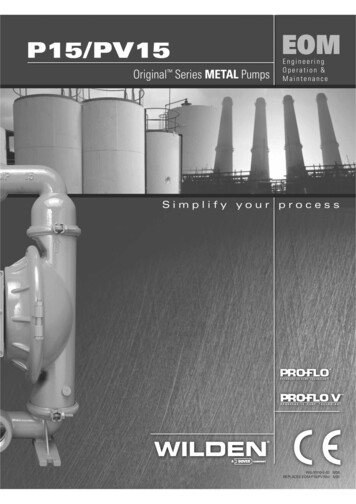
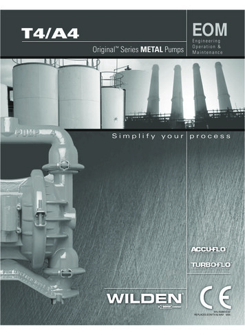
EOMT4/A4Original Series METAL PumpsEngineeringOperation &MaintenanceSimplify your processWIL-10260-E-02REPLACES EOM T4 & A4M 4/05
TABLE OF CONTENTSPAGE #1SECTION 2 — PUMP DESIGNATION SYSTEM .2SECTION 3 — HOW IT WORKS (PUMP & AIR SYSTEMS) .3SECTION 4 — DIMENSIONAL DRAWINGSA. T4 METAL Air-Operated .B. A4 METAL Accu-Flo .C. T4 METAL SANIFLOFDA Air-Operated .D. T4 METAL Stallion .4455SECTION 5 — PERFORMANCE CURVESA. T4 METAL Rubber-Fitted .B. T4 METAL Ultra-Flex -Fitted .C. T4 METAL TPE-Fitted .D. T4 METAL PTFE-Fitted .E.T4 METAL Stallion Ultra-Flex -Fitted .F.A4 METAL Accu-Flo Rubber/TPE-Fitted .G. A4 METAL Accu-Flo Rubber/TPE 70/30 Operating Condition .H. A4 METAL Accu-Flo Ultra-Flex /PTFE-Fitted .I.A4 METAL Accu-Flo Ultra-Flex /PTFE-Fitted 70/30 Operating Condition .66778991010SECTION 6 —SUCTION LIFT CURVES & DATAA. T4 METAL Air-Controlled .B. A4 METAL Accu-Flo .1111SECTION 7 — INSTALLATION & OPERATIONA. Installation — Turbo-Flo Suggested Installation Drawing .B. Operating and Maintenance .C. Principles Behind Accu-Flo Pumps.D. Installation — Accu-Flo .E.Suggested Operation and Maintenance .F.Troubleshooting — Turbo-Flo .G. Troubleshooting — Accu-Flo .12131414151616SECTION 8 — DIRECTIONS FOR DISASSEMBLY/REASSEMBLYA. T4 METAL Wetted Path — Tools Required, Torque Specs, Cautions .B. Turbo-Flo Air Valve/Center Block – Disassembly, Cleaning, Inspection .C. Reassembly Hints & Tips .D. PTFE Gasket Kit Installation .17202223SECTION 9 — EXPLODED VIEW/PARTS LISTINGA. T4 METAL Rubber/TPE-Fitted .B. T4 METAL PTFE-Fitted .C. A4 METAL Accu-Flo .242628SECTION 10 — REFERENCEA. Air-Operated Elastomer Options.B. Stallion Elastomer Options .C. Accu-Flo Electrical Reference .303031ClassSECTION 1 — CAUTIONS .I&II OzoneNNOSEbsDep Uleting Sutancesct 0ir An A 199lea nts ofC.U.S ndmeeAm
SECTION 1MODEL T4 METALCAUTIONS – READ FIRST!TEMPERATURE LIMITS:Polypropylene0 C to 79 CPVDF–12 C to 107 CNeoprene–17.8 C to 93.3 CBuna-N–12.2 C to 82.2 CEPDM–51.1 C to 137.8 CViton –40 C to 176.7 CWil-Flex –40 C to 107.2 CPolyurethane 12.2 C to 65.6 CSaniflex –28.9 C to 104.4 CPTFE4.4 C to 104.4 C32 F10 F0 F10 F–60 F–40 F–40 F10 F–20 F40 FtotototototototototoCAUTION: Blow out air line for 10 to 20 secondsbefore attaching to pump to make sure all pipe linedebris is clear. Use an in-line air filter. A 5µ (micron) airfilter is recommended.175 F225 F200 F180 F280 F350 F225 F150 F220 F220 FNOTE: When installing PTFE diaphragms, it is important to tighten outer pistons simultaneously (turning inopposite directions) to ensure tight fit.NOTE: Tighten clamp bands and retainers prior to installation. Fittings may loosen during transportation.NOTE: Before starting disassembly, mark a line fromeach liquid chamber to its corresponding air chamber.This line will assist in proper alignment during reassembly.CAUTION: When choosing pump materials, be sureto check the temperature limits for all wetted components. Example: Viton has a maximum limit of 176.7 C(350 F) but polypropylene has a maximum limit of only79 C (175 F).CAUTION: Verify the chemical compatibility of theprocess and cleaning fluid to the pump’s componentmaterials in the Chemical Resistance Guide (see E4).CAUTION: Maximum temperature limits are basedupon mechanical stress only. Certain chemicals willsignificantly reduce maximum safe operating temperatures. Consult engineering guide for chemical compatibility and temperature limits.CAUTION: When removing the end cap usingcompressed air, the air valve end cap may come outwith considerable force. Hand protection such as apadded glove or rag should be used to capture theend cap.CAUTION: Always wear safety glasses when operating pump. If diaphragm rupture occurs, material beingpumped may be forced out air exhaust.CAUTION: Only explosion proof (NEMA 7) solenoidvalves should be used in areas where explosion proofequipment is required.WARNING: Prevention of static sparking — If staticsparking occurs, fire or explosion could result. Pump,valves, and containers must be properly grounded whenhandling flammable fluids and whenever discharge ofstatic electricity is a hazard.NOTE: All non lube-free air-operated pumps must belubricated. Wilden suggests an arctic 5 weight oil (ISOgrade 15). Do not over-lubricate pump. Over-lubrication will reduce pump performance.CAUTION: Do not exceed 8.6 bar (125 psig) air supplypressure.NOTE: On cast iron pumps equipped with PTFEdiaphragms, balls and sealing rings, PTFE gasket kitsshould be utilized.CAUTION: Before any maintenance or repair isattempted, the compressed air line to the pump shouldbe disconnected and all air pressure allowed to bleedfrom pump. Disconnect all intake, discharge and airlines. Drain the pump by turning it upside down andallowing any fluid to flow into a suitable container.WIL-10260-E-02NOTE: UL-listed pumps must not exceed 3.4 bar (50psig) air supply pressure.1WILDEN PUMP & ENGINEERING, LLC
SECTION 2WILDEN PUMP DESIGNATION SYSTEMT or A4 X / X X X X X / XXX / XX / X XX / XXXXMODELO-RINGSVALVE SEATVALVE BALLSDIAPHRAGMSAIR VALVECENTER BLOCK OR CENTER SECTIONAIR CHAMBERS OR CENTER SECTIONWETTED PARTS & OUTER PISTONAIR SYSTEM BASE TYPESPECIALTYCODE(if applicable)T4 OR A4 METAL MATERIAL CODESAIR SYSTEM BASE TYPEDIAPHRAGMSVALVE BALLATBNSBNUEPSEPUFSS NESNEUPUSTEU BN BUNA-N (Red Dot)EP EPDM (Blue Dot)FS SANIFLEX [Hytrel (Cream)]NE NEOPRENE (Green Dot)PU POLYURETHANE (Brown)TF PTFE (White)VT VITON (White Dot)WF WIL-FLEX [Santoprene (Orange Dot)] ACCU-FLO TURBO-FLO WETTED PARTS& OUTER PISTONAASSWWWM ALUMINUM / ALUMINUMSTAINLESS STEEL / STAINLESS STEELCAST IRON / CAST IRONCAST IRON / MILD STEELAIR CHAMBER/CENTER SECTIONACMNP ALUMINUMPTFE-COATED ALUMINUMMILD STEELNICKEL-PLATED ALUMINUMPOLYPROPYLENECENTER BLOCK / CENTER SECTIONACNP TNU TSUVTSVTUWFSALUMINUMPTFE COATED ALUMINUMNICKEL PLATED ALUMINUMPOLYPROPYLENE BUNA-N (Red Dot)BUNA-N, ULTRA-FLEX (Red Dot)EPDM (Blue Dot)EPDM, ULTRA-FLEX (Blue Dot)SANIFLEX [Hytrel (Cream)]NEOPRENE (Green Dot)NEOPRENE, ULTRA-FLEX (Green Dot)POLYURETHANE (Clear)PTFE W/EPDMBACK-UP (White)PTFE W/NEOPRENEBACK-UP (White)PTFE W/SANIFLEX BACK-UP (White)VITON (White Dot)VITON , ULTRA-FLEX (White Dot)WIL-FLEX [Santoprene (Orange Dot)]AIR VALVEABCDNS ALUMINUMBRASSPTFE COATEDBRASS W/OIL BOTTLENICKEL PLATED BRASSSTAINLESS STEELVALVE SEATABNEPFS HMNEPUSVTWF ALUMINUM*BUNA-N (Red Dot)EPDM (Blue Dot)SANIFLEX [Hytrel (Cream)]ALLOY C*MILD STEEL*NEOPRENE (Green Dot)POLYURETHANE (Brown)STAINLESS STEEL*VITON (White Dot)WIL-FLEX [Santoprene (Orange Dot)]*No valve seat o-ring required.VALVE SEAT O-RINGFS FLUORO-SEAL TF PTFE (White)SPECIALTY 0010201030104010501080109Spark freeSpark free, SS outer pistonBSPTSpark free, BSPTWing nutsScreen basedScreen based, spark freeScreen based, BSPTScreen based, spark free, BSPTStallion , balls & seats ONLYStallion , shaft & bumpers ONLYStallion , internals, BSPTStallion , internalsStallionStallion , BSPTSaniflo FDA, Wil-Gard II 220VSaniflo FDASaniflo FDA, Stallion internalsTri-clamp fittings, wing nutsTri-clamp fittings ONLYUL listedUL listed, Wil-Gard II 110VUL listed, screen basedWil-Gard II 110VWil-Gard II sensor wires ONLYWil-Gard II 220VWil-Gard II 110V, spark freeSpark free, Wil-Gard II 220VBSPT, Wil-Gard II 220VSpark free, BSPT, Wil-Gard II 01660167016801690180Stallion , internals, spark free, BSPTSaniflo FDA, Wil-Gard II 110VSaniflo FDA, Accu-Flo , 24 V DC x-proof coil, Intl.,PTB approvedSaniflo FDA, Accu-Flo , 110V AC coilSaniflo FDA, Accu-Flo , 24 V AC / 12V DC coilSaniflo FDA, Accu-Flo , 24V AC / 12V DC x-proof coilSaniflo FDA, Accu-Flo , 110V AC x-proof coilAccu-Flo , 110V AC x-proof coil, BSPTAccu-Flo , 110V AC coil, BSPTAccu-Flo , 110V AC x-proof coil, Wil-Gard II 110VAccu-Flo , 24V DC coil, spark free, BSPTAccu-Flo , 24V DC coilAccu-Flo , 24V AC / 12V DC coilAccu-Flo , 24V AC / 12V DC x-proof coilAccu-Flo , 24V DC x-proof coilAccu-Flo , 110V AC coilAccu-Flo , 110V AC x-proof coilAccu-Flo , 24V DC x-proof coil, Intl. PTB approvedAccu-Flo , 24V DC x-proof coil, Intl., PTB approved, BSPTAccu-Flo , 24V DC coil, Intl., PTB approved, DIN flangeAccu-Flo , 24V DC coil, BSPTAccu-Flo , 24V DC x-proof coil, BSPTAccu-Flo , 24V AC / 12V DC coil, BSPTAccu-Flo , 110V AC coil, Wil-Gard II sensor wires ONLYAccu-Flo , 24V DC coil, Wil-Gard II 110VAccu-Flo , 24V AC / 12V DC coil, Wil-Gard II 110VAccu-Flo , 110V AC coil, Wil-Gard II 110VAccu-Flo , 110V AC coil, PFA coated hardwareAccu-Flo , 24V AC / 12V DC coil PFA coated 060406060608Accu-Flo , 24V AC / 12V DC x-proof coil,PFA coated hardwareAccu-Flo , 24V AC / 12V DC x-proof coil,Wil-Gard II 110VAccu-Flo , 24V DC coil, PFA coated hardwareAccu-Flo , 24V DC x-proof coil, PFA coated hardwareAccu-Flo , 24V DC coil, spark freeAccu-Flo , 24V DC x-proof coil, spark freeAccu-Flo , 24V AC / 12V DC coil, spark freeAccu-Flo , 24V AC / 12V DC x-proof coil, spark freeAccu-Flo , 110V AC coil, spark freeAccu-Flo , 110V AC x-proof coil, spark freeAccu-Flo , 24V DC coil, DIN flangeAccu-Flo , 110V AC coil, Stallion internals (balls & seats)PFA coated hardware, Wil-Gard II sensor wires ONLYStallion , externals (screen)SS outer piston, SS clamp bands and hardwareStallion , externals (screen), BSPTPFA coated hardware, BSPTWing nuts, BSPTPFA coated hardwareDIN flangeDIN flange, PFA coated hardwareSS outer pistonsPFA coated hardware, Wil-Gard II 110VDIN flange, Wil-Gard II 220VDIN flange, PFA coated hardware, Wil-Gard II 220VPFA coated hardware, Wil-Gard II 220VNOTE: MOST ELASTOMERIC MATERIALS USE COLORED DOTS FOR IDENTIFICATION.Viton is a registered trademarks of DuPont Dow Elastomers.WILDEN PUMP & ENGINEERING, LLC2WIL-10260-E-02
SECTION 3THE WILDEN PUMP — HOW IT WORKSThe Wilden diaphragm pump is an air-operated, positive displacement, self-priming pump. These drawings show the flowpattern through the pump upon its initial stroke. It is assumed the pump has no fluid in it prior to its initial stroke.RIGHT STROKEMID STROKELEFT STROKEFIGURE 1 The air valve directs pressurized air to the back side of diaphragmA. The compressed air is applied directlyto the liquid column separated by elastomeric diaphragms. The diaphragmacts as a separation membrane betweenthe compressed air and liquid, balancing the load and removing mechanical stress from the diaphragm. Thecompressed air moves the diaphragmaway from the center block of the pump.The opposite diaphragm is pulled in bythe shaft connected to the pressurized diaphragm. Diaphragm B is on itssuction stroke; air behind the diaphragmhas been forced out to the atmospherethrough the exhaust port of the pump.The movement of diaphragm B towardthe center block of the pump creates avacuum within chamber B. Atmosphericpressure forces fluid into the inlet manifold forcing the inlet valve ball off itsseat. Liquid is free to move past the inletvalve ball and fill the liquid chamber (seeshaded area).FIGUR
THE WILDEN PUMP — HOW IT WORKS The Wilden diaphragm pump is an air-operated, positive displacement, self-priming pump. These drawings show the flow pattern through the pump upon its initial stroke. It is assumed the pump has no fluid in it prior to its initial stroke. FIGURE 1 The air valve directs pres- surized air to the back side of diaphragm A. The compressed air is applied directly to .
