Transcription
- - - . -.TRANSCO'' ''O.*.4!t.'.-TRANSCO TEST REPORT TR-IlO;FIRE AND HOSE STREAM TESTSOF TCO-OO3 HIGH DENSITY-,'SILICONE ELASTOMER.:!.40.1,.-!.'.- - - .,.;.By-G.J. aroszDate: 4 22-83.a.JO-.8309270572 830920PDR ADOCK 05000454F. . --.-. --,. .--.,'PDR. .,. ,., -. . . ., .-- . ,., . . - - . . -
.*,***Test Report #TR-110'*(])Page 1 of 23,A)Synopsis:This report describes a three hour fire and subsequent hose stream floor test of Transco #TCO-003 High Density SiliconeElastomer installed 12" deep in three electrical openings.Thetest was perf ormed in accordance with the ASTM E-119-time / temperature curve f'or three hours along with provisionsset forth in the IEEE 634-78, AN1, NML, and ASTM E-814 (for a'"F" rating) test standards.These penetration seals weretested along with twenty-four other penetration seals in a,17'-9" x 13'-10-1/2" x 12" thick concrete slab on March 9,1983.at Portland Cement Association's Fire Research Laboratory(Skokie, Illinois).'.The test specimens consisted.of three simulated electrical.-openings which measured 72" x 32" (penetrated. by two 30" x 4".and one 24" x 6" cable trays and two conduits) and 1-1/2" and6" diameter embedded conduits.All trays and conduits werefilled in excess of 100% loadings with PVC jacketed cables(with'the exception of the 24" x 6" tray which was filled withHypalon jacketed cables).s.'.The symmetrical penetration seals consisted of 12" of #TC6-003High Density Silicone Elastomer (no permanent damming mate-.rial was used). The elastomer weighs 150 lbs./ cubic foot (min.)and is normally used for sealing penetrations in radiationgqgQshield walls or floors.--.*
{Test Report #TR-110',Page 2 of 23*-.Besides qualifying the seals to the test standards mentioned,.Theseseveral other objectives were established in this test.are:-1) .The material's ability to seal both narrow and wide areaswithout support;.,'2)The use of the material when installed next to eithersteel or concrete s6bstrates;,,3)The use of the material to seal both solid and ladder backcable trays; and,4)The ability of the sealing catorial to be removed for'additional cable installation.(use of temporary plugs);.B.)0Test Slab:The test sieb meeeered 17 -9x 13'-10-1,2x 12 thicx.Twenty-seven openings which ranged from 1-1/2" diameter to' 109-1/2" x 32" in size penetrated the test slab.Thepenetrations were arranged in the slab so that 18" vide (min.)concrete columns separated each row of penetrations. These-columns were placed in the direction which rould allow for theleast amount of deflection from heat during the fire test.1iThe slab's steel reinforcement design and slab f abrication werecompleted by Portland Cement Association's personnel.the slab was cast, the concrete was allowed to dry for severaljdays af ter which the slab was subjected to additional heat! Aftercuring on a furnace.0.1.------ - - ---.
- -,Test Report #TR-110.-.*-*Page 3 of 23The slab's superstructure, specimen fabrication and seal,installations were performed by Transco eeployees.The slab'ssuperstructure consisted of steel angle braces mounted to the slabwhich supported the pipes, cable trayq, cables, etc.; for the test.C.)Specimen Configurations:The large rectangular tes't penetration was 72"'x 32" x 12".deep. Two sides of the penetration were lined with 1/4" thicksteci plat(set at a right angle in the plan view of the pene-tration). The remaining two substrate surfaces were cast conIcrete.This opening was penetrated by three cable trays and a 6" and 2"(hdiameter conduit.Each cable tray was mounted so that it extended36" above the slab's unexposed surf ace and 12" below its exposed.surface. The conduits were 12" long and were mounted flush inside ofthe penetration.One 6" and one 1-1/2" diameter (x 12" long) rigid steel conduits werealso cast into the concrete slab outside of the large rectangular'opening. These were used to simulate embedded conduits (or sleeves)* 'which pass through walls or floors.The cable trays and conduits were filled with cables based on loadingswhich exceeded 100% fills. The loadings were calculated so that a100% fill was equivalent to 40% of the actual sectional area ofO. - , . .- ,n. - -, . - -
Vest Report FIR-fTDi.Page 4 of 23'.,'( .Some of.the loadings were increased sothe cabic trays'or conduits.that 100% visual loadings were also achieved.as follows:Cable loadings were.A.)32" x 72" RECTANGULAR OPENING:1.)30" x 4" ladder back tray filled with PVC jacketed cable:.134 2 / c # 14. . . . . . . . . . . . . . . . . . . . . . 0.137 2 . . . . . . . 18. 3 84 8/ 35 12/c'#14. 0.5329. 18.6190.500MCM.'.'.0.7013. 26 1/c,Total Loading (115% fill of tray)-18.235955.2397 sq. in.2.)30" x 4" solid back tray filled PVC jacketed cable:1342 / c # 14 . . . . . . . . . . . . . . . . . . . . 0.137 2 . . . . . . . 18. 3 84 835 12/c.26,,#14. 0.5329 . 18.61901/c, 500MCM. 0.7013 . 18.2359Tota.1 Loading 55.2397 sq. in.(115% fill of tray).,*Two 2/c #14 and one 12/C #14 cables were added to this tray aspart of the repair to this seal.i3.)24" x 6" solid back cable tray filled with Hypalon jacketed cable:186(})#16. 0.1046. 1.8828# 16 . . . . . . . . . . . . . . . . . . 0 .2 87 4 . . . . . . . . . 1. 69 6 4#16;. 0.6792. 9.50888 12 pr. #16 . 0.9160. 7.32803#14. 0.1839. 0.55172/C4#14. 0.2058. 0.82323/c3#14. 0.2715. 0.81454/c'14#14. 0.3717. 5.20387/c9#14. 0.4938. 4.44429/C#14. 0.7013. 3.50655 12/c64/0. 2.6822. 16.09323/C21/0. 1.6695. 5.36443/C1500ncM. 5.2563. 5.25633/c62.4738 sq. in.Total Loading (162.6% fill of' tray)*one 12/C #14 cabic was added to this tray as part of the repair tothis seal.14.1 pr.2 pr8 pr.'.4--
lTest Report #TR-110.*.'(hPage 5 of 23**4.)2 It/C.I2 / C # 14 . . . . . . . . . . . . . . . . . . . . . . 0.183 9 . . . . . . . . . 0. 5 5173-!3" diameter conduit filled with Hypalon jacketed cable:#14.'.1.4260.7013 .1.42663/C,6/0. 0.7133.Total Loadin7 23.3809 sq. in.(119.5% fill of conduit)*.5.)30,*6" diameter conduit filled with PVC jacketed cable:2/ c # 14. . . . . . . . . . . . . . . . . . . . 0.137 2 . . . . . . . 4 .116 08 12 / c # 14 . . . . . . . . . . . . . . . . . . . .0 . 5 3,2 9 . . . . . . .4.26321/c, 500MCM.0.7013 .4.90917.Total Loading 13.2883 sq.in.(117.4% fill of conduit)., ,B.)1-1/2" diameter embedded conduit filled with PVC j acketed cable(separate penetration):32/C #14. 0.1372 . 0.4116.I 12/C #14. 0.5329 . 0.53290.9445 sq. in.Total Loading (113.6% fill of conduit)C.).6" diameter embedded conduit filled with PVC jacketed cable'(separate penetration):302 / C # 14 . . . . . . . . . . . . . . . . . . . . . 0.137 2 . . . . . . . . 4 .116 08 12/C #14. . . . . . . . . . . . . . . . . . . . . 0. 5329 . . . . . . . . 4.2 63271/ C 500McM. . . . . . . . . . . . . . . . . . 0. 7013 . . . . . . . . 4. 909113.2863 sq.in.Total Loading -{{g(117.4% fill of conduit).-- --., -,-- - - - - - -
.Test Report #TR-Il0.,*-.'23Page 6 ofAll cables used in the test extended 36" above the slab's unexposed surface and 12" below its exposed surface.Cables wereheld to the trays with both compression clamps and metal plateslocated approximately 12" from the to,p of each tray.In ad-dition, a threaded rod was used across the bottom of each trayto prevent the cables from being pulled forward during the sealinstallation.' This was done to simulate field conditions where.continuous cable make it impossible in some cases to move the.-cables apart for seal installation.The top ends of all cables used inside of the cable trays werecovered with silicone adhesive while conduit ca'ble ends wereThis was done in accordance withcovered with electrical tape.'( hIEEE 634-78 r.equirements.Finally, the cables used in the conduits were grouped andmounted by type (i.e., power, control and instrument cables).The grouping of power cables in each conduit sleeve created a.more severe condition because of the high concentation of heatthat would be produced during the fire test.* D.)Seal Installation:The openings were first dammed by packing mineral wool betweenthe cables to prevent leakage of the liquid high densitysilicone elastomer material.The rest of the opening was formedwith plywood. Once the elastomer was installed and set, allOforming materials were removed.- -. ,- -4
.Test Report #TR-110,"*--Page 7 of 23*The two-componcht hi;;h density silicone clastomer were ir. stalledOin a one to one ratio ( /- 5%) 12" deep inside of the largepenetration and conduits.A portion of the seal was installed'using dispensing equipment while the remainder of the seal was. completed with large (30 gallon drum) hand mixed batches. L'herethe elastomer was used in cable bundles, t .; . bundles were spreadapart by hand. ,A trowel was used to push'the elastomer into the.cable bundles to facilitate its flow.Once,the elastomer installation was completed, the dammingmaterial was removed.It was noted at this time that a smalllayer of material at the elastomer /PVC jacketed cable interfacedid not completely cure. The inhibition of cure at the PVC'-Oserraces wes attribeted to the free se1 Pher in the PvCmaterial.Sulphur is a material which affects the curing.'mechanism of the platinum catalyst silicone product. Although.the amount of inhibition varied from PVC jacketed cable to-cable, none was ircediately observed at the siliconeelastomer /hypalon jacketed cable interfaces.No attempt wasmade to repair t;he seal where inhibition occurred in order to !show both conditions.I'Ii'E.)fThermocouples:;;Thermocouples were mounted to the test specimens to gather tem.'perature data throughout the test at five minute intervals forthe first two hours and at ten minute intervals for the ressinOing hour (in accordance with the IEEE 634-78 standard). Temper-stures were recorded for the seal surfaces, seal / substrate4.- -interfaces (unexposed surface only), and penetration members.-.--.--.,
j'-.,-.Test Report #TR-110.Page 8 of 23*All seal surface thermocouples were embedded 1/4"-1/2" into seal.surfaces to prevent the effect of contact with ambient air tem,peratures. Thermocouples used for monitoring cable temperatures.were tied with wire to the cables so that their tips were alsoembedded into the seal surface.*.The thermocouples used in this test along with final to:peraturereadings are as follows (temperature data for the entire test can'be found in section "H" of this report):,.T/C# Print # Description-Final Temperature (*F)9cSeal surface118.092 92cSeal surface109.093 93cSeal surface102.094 94cInstrument cable187.0 ---95 95cControl cable185.0tray with Hypalon96 96cPower cable174.0jacketed cable97 97cCable tray181.098 98cSeal surface283.099 99cInstrument cable329.0-- Conduit filled100 100cControl cable316.0with Hypalon101 101cPower cable327.0Jacketed cable102 102cInterface303.0103 103cInstrucent cable186.0104 104cControl cable350.0 --Ladder back tray105 105c.Power cable434.0filled with Pyc106 106cCable tray186.0jacketed cable91,*Solid back cabic-.- ,,.:.--,.
.'.1Test Report iTR-110I*Page 9 of 23.T/C# Prints DescriptionFi.nal Temperature ('F)107 107cInstrument cable166.6-108 108cControl cable333.0 --- Solid back tray109 109cPower cable385.0filled with PVC180.0jacketed cable.110 110e* Cable tray.11197bSeal surface323.811224bInstrument cable361.411328bControl cable11425bPower cable-- Conduit filled w/.PVC jacketed cable'378.8.486.8'(h11526bInterface11627bSteel substrate /117 117c,'339.8steel interface301.5Concrete substrate /Seal surface126.0-186 186c.Seal surface102.0187 187c ' Seal surfaca94.0188 188c94.0Seal surface.21323bRepair surface92.121429bRepair cable99.7 -- PVC jacketed cable21543bRepair surface109.221642bRepair cable110.9--Hypalon jacketedcableO.,m --- . w w m.,. , , -n v-m,.aom
I.-.Test Report #TR-Il0(Page 10'of 23.,.1-1/2" Embedded steel conduit / sleeve:7520aSeal surface7621aInterface7722aInstrument cable*188.3.164.7'-191.9-.6" Embedded steel conduit / sleeve:78204.9Seal surface28a6'7929Instrument cable494.28032aControl cabic412.1813C sPower cable591.28231aInterface.-''.257.8.F.)Furnace:.The furnace used for this test measures approximately 14' x 18' at itssupport points.It is approximately 7' tall making it possible towork on the specimen's exposed surface and view it prior to the firetest. The furnace atmosphere is controlled by six self-ignitingburners which burn natural gas and operate in unison.The burners areautomatically controlled by a computer located inside of the control;.,room. As the furnace atmosphere temperatures are monitored in thecontrol room, manual adjustments can be made to the burners to account,for varying amounts of fuel contribution throughout the test.b. . .e--e-,
.,.*Test Report *TR-110)Page 11 of 23.The furnace atmosphere temperatures a're monitored by 16 thermo.couples located 12" beloa the test slab.These te peratures areindividually printed on a continuous chart and also averaged on acomputer printout.The furnace draft is manually operated and averages to approxi,mately.08" of water pressure throughout the test.Since manual,adjustments are made to the burners in order to follow the ASTME-119 time / temperature curve, brief periods of positive pressureare introduced inside of the furnace.--(:)This is evidenced by'visible puffs of smoke generated through openings in the testspecimen (i.e., through a fire damper, unsealed pipe insulation,,.etc.).''G.)Test Record:The fire test was conducted for three hours in accordance with'the ASTM E-Il9 time temperature curve.Throughout the test, aneven blanket of flame covered the plan area of the furnace.Allcombustible materials located on the exposed surface of the slabquickly ignited and continued to char throughout the test.During the first 2 hours of the tests, very little smoke wasgenerated from the cables used in this specimen. Light snoke()from the cables occurred for most of the last hour of the test.- - , , -
*.-.Test Report #TR-110i)Page 12 of 23.Between 3 hours and 3 hours,1 minute (af ter the fire test) thecenter of the seal bulged up approxi ately 4" above the slab and.cracked.The "U"-shaped crack was studie.d af ter the test and itwas determined that the crack was caused by the thereal expansion-of the growing bulge and not by the fire burning through theseal.The material at the break where the thereal expansion tookplace was approximately 3/4"-1" thick.,*.*.The hose stream tests were conducted on the concrete slab and 3penetration seals. Water did not penetrate the two embedded-(:).conduit seals and the t'wo conduit spals (conduits whichpenetrated the large opening)*. Because of tha crack, it was not,,possible to perform a meaningful hose stream' test on the large.seal.The two hose stream tests were conducted for 6 minutes and 18seconds each in accordance with the following requirements:a.) IEEE-634-78:75 p.s.i. hose stream delivered throughan 1-1/2" hose equipped with a fog nozzle set at a discharge.angle of 30' from a distance of 10'.b.) ANI:'Same as above except that the nozzle was set at a dis-charge angle of 15*.@'.,*
.-.Test Report l'TR- 1100-.race 13 of 23.II.)'""Temperature Data:The following sheets identify both furnace atmosphere andunexposed surface temperatures obtained throughout the fire test.eO. .e.eNO./* .m,emv
Page Irl of 23.-***'1 F.ht t *:.C C C F %*5 6 ) - V a / 0 9.* n .'FUF:ll AE E ATI;95.F HEF.E T E i:* E f. A1 UT:E !. E C . F . o.TEE,T T IllE ,F URit's C EASTil C119\* A F: 16TICIl FPO:Hr-: It i r.T E!!P.T E!!T .AS.Tl! TEi:T .'.FF.**0:0019 20'.,5: 25*0:30*0:35"'0:400: 45*-.'0:50*-0:55*;1:00 1:051:10.1:151:20.*. .81:251:30-1*;-1:351: 001854185042:1018731862112:2018801880189519161930* 18752:30*t S'103618441:50,**F2:402:503:001 '-1843-1'18881900191219255-8-545.O-.,-, ,--,
TRANSCO.P, u a u.THERbOCCUPLESTEST TIME(temport.tures in dk: recs F)HR: MIN1110:0072.00:0572.1'0:100:150:200:250: 300: 350:400:45'0: 500: 551:001:051:101:151:201:251: 301: 351:401: 451: 501: 55* 02:202: 302:402: 503:00,11211371.172.972.373 0 -89.699 2110.6123.1136.1149 5160.9174.4187.7200.5212.9225.2237.0248.7259 7235.3244.1252.3260.6268.4284.4299 06.9221.4241.3267.7-31.0.5s!-.O.
IHANbbU*."-lPcge 16 of 23,-.THERMOCCUPi.ESTEST Tli.'EHR:fSr4(temperatures in degrees F)'11776720:000:05'0:1073737373730:150:20-0:250: 300: 350:40 -.0: 450: 50'0 : 551:001:051:101:15'1:20.80821:251: 301:351: 40.g-1:451: 501: 552:002:102:20-74747474747575767883838688909395100 105110115120126.2: 573737373. 29421321471.9 6.471.571.772.172.873.373 82.082.783.785.486.888.290.092.1*. --.Ne90.385 186.087.088.791.292.994.997.299.7 .-
Page 17 of 23.-.THERI.iOCCUPLESTEST Tif.'E(temperatures in degrees F)HR;f.i!N,0:000:050:100:150:200:250: 300: 35,0: 500: 551:001:051:101:151:201:251: 301: 351:401:45Av.1: 501: 55.2: 503:00-73 173 173 97.4100.5104.4108.27 3. '73.473.673.874.174.575 7.488.990.592.896.299.8013 1106.9110.974.474.875.475.976.677.5.78.479.480.681 983.184.1''84.8. . -.i73 173 173.173 173.373.473.573.787.589 191.594.898.4101.8105.3109 22:40275' 86.02:002:102:202: 30,-216,74.00:400:45.215777672.372 73.675.277'.379.782.284.887.589 993.094.6101.2105 9128.8135 72.h72.172.872.375.4E1.272.873.993.875.5 104.377.7 120.380.5 13f.585.1 152.989 1 167.593.8 160.198.7 203.2104.7 218.1110.5 230.9115.7 2hh.5120.5 257.7128.6 269 7133 5 292.6140.8 295 5143.5 307.9149.1 319.2154.3 333.4160.9 345.6163.1 358.1164.21 369.4174.5 389.h193.0 413.0192.2 h33 0195.0 451.6203.8 472.4204.9 494.2-. .-,v. .,.S'',, ,, 7978-1.O.
TRANSCO.e,,,, , ,, 2 3. "THERMOCCUPLESTEST TIME(temperntures in degrees F)HR: 50:400:45'1:00-1:051:101:151:201:251: 301: 351: 401: 451:50V.1: 55'2:00.2:102:202: 302:40'2: 503:0072.873 1P.2229.7240.4250.8262.5274.7287.3299 0309 3319.5326.8336.0347.5361.3377.4393 9412.10: 500: 55,a-106.P0: 300: 298.4312.7325.6337.2349 3363 .1102.6109.6117.1124.2132.4190.2148.9157.7165 9172.1178.8184.2191.0195.4199 2.'' --. 209.8'224.3232.0240.2250.1257.8. .e\.;-.oO
TRANSCO.g ,ge i , ,, 23,.THERIAOCCUPLESTEST TifAEHR:fAliJ(temperatures .in degrees F)-;,929193 0:000:05767373737373740:10-0:150:200:250: 300:VO0: 450: 500: 551:001:051:101:151:201:251: 301: 77777777777778787980-.1: 552:00'2:'10. .2:202: 082892: 507673737373 '74'0:350,--.102109. , 77778788192*--e .,*.,e\eeO
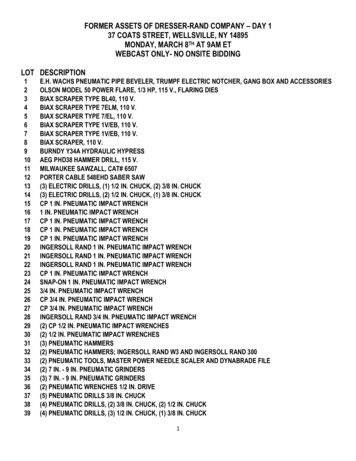
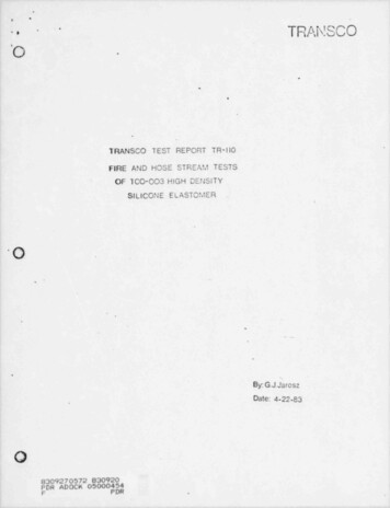
* .Test Report #TR-Il0()Page 20 of 23-.*Post Test Observations:I.)The large electrical opening and all cohduit sleeves successfullycompleted the,three hour long fire test. Because of the ther al'expansidn crack which occurred af ter the fire test in the largeopening it was not possible to conduct the hose stream test forthis seal.,tThe unexposed seal surfaces (with the exception of the crack) in.all openings were not af fectsd by either the fire or hose streamtests.,'Swelling of the PVC jacketed cables occurred in all casesat the seal ' surfaces. The attached sketches indicate the amountof material remaining in the large opening at the conclusion of.the test.*N ,.N.O--.;--. - -,,- . .,,.,. .- .,,., m.-- ,--.y-%.
t.TRANSCconcrete substrate4'x 30" solid backtray with PVCjacketed cable. [-*.igg.o--i4---Y----- 2. : :. ,a. -Q:Q.v-t'. V P .' ' N :. . w ;C' A ' d 4 .u: A?.:6, &W4:7)';{AACKw.{1.5'&6"dia.embcddedconduits with PVC jackcted77 ae2sicable.PB,-.-%, .c.3if,% .r'kB.::.: ".*' ?substrate .-''.c :- y',.6" dia. conduit with :[,cd ''.: N . cPVC jacketed cable-'-high density-by;97W.G.vs.ec ;.t:. .: .--.,steel-.#D':.4A44. -.:g .f-(*r ?,-u.y ;. :s,.A yA.,h.w' . . .?I". . ,r :th. ?'.'n !.aAj.*.A'Y V. eNJ* .,%, '.-. *".-. ',a.7N.;;- Aa.-:-(.A",.e-.'.sm 3 dia. conduit with .'.;';', ;. "' 'g-.silicone e!aste:seal (12, thick)3"HYPALON jacketed.p; cable,.-N.j,n.Lp% F. .;.**. v u -. -N. M; ;.'- .:. -.4'x 24" solid bacb:,i*I'm gtray with HYPALON ;1acketed cable., -.,.O.c %%M;:p L, '' !-concretesubstratenAaI,-r W.o ;Sm;::.rg;g'.-(.m L t x , A ,."(O.-j.ua-:,'-.S. .;ir1. mc 'coe my .: .,3;.4.-b. . r.;; :-TMii.e,nw .;,htM.i.Sc6"x 30' ladder backi*:'.:'q.14,. -W*X's::'. ;.&, . ? . * :.?steel substrate-EA. xY.A O 325, .;'.n -;:- ;;'; .-;,.e.: r.-.: J. . . , .:. r; . . Q .- -. .r.'b.;3.-. . .;:. :' - .w ' u *- - ', -.a-"4:: ::2 w. : 5-'PLAN VIEW-'.HIGH DENSITY SILICONE ELASTOMER PE N E TR ATIONSEALS
TOAf!Q I i i n ixw.-o,. ! . I .6s f.,.'li l i,q l p.bu q t. ij't.mai:i,.- d.l uit. . i. nf i "p: o."iCable tray.ib;II!!I5!fII'NIu!i li!M:ij ;'li U Ubi 'jband Cables ------ ,'o.g.j@}w. h. .@@@W]:*t,,Cable bracket.D.'.y2,. 1.I' e.i r p.u p.n,6n. .ij j:.n:ll t.,,f. i,t:-.-.m.,.:.a,.;jjyj['F,.*y.I).; , . ., ?,.p.pt ,i.p.ww,i, .-"',ulintjgp4.m . .-,11 : t1. N2: 4.:. G'rt.y,y,. o cc . y 7, , f. f, y, c, cf, g c, , ./.',',y'.g,.,yggf.g, ,yL**'',,.,gg,. 3 f g . , . , fy,,.NN/w wNN /.7, / W.Y, W. /. . N . Nc/.sv.N8/NsN,v.W,yN W"N.W. N, Nw/. e yA ,.N v. c a .,y,w,WN, ,g gg, yj, , f,'f, , , . , , , , ,'f y j,Ipv.y, ,w , ;.,.yV.',,.,sfy, , j,yj g,.:* ? ,-,WNN, /,/. . . /, N?N,W;N %'Nir'./ ',/,/? /chW.'w.y% .'.N y'. t/: . W ; ?. ', . .N/.% N/ ' WNe .' /,W//.*?.NNY./, N W W**p W .4.[. . N.Ni/.W./.,w. . w .nN,/N.w w.wc/., 'N. .,,W*xg9",,W.N.w,wy w.jv, w,.WN.W/.rr. , // * VNN, N.y/// VN//Ny: . ,WN/.W/Ns WNN//.? N, yna h./ v9N.vNNu. . .W. N v,-Ie,.C,N !.-% NNW ."/N-w.,.Wi.Wci'c%W.w.,Ni.Y, / .c,w.we. N v.g? ,".//, .WN.'', n", , NiN./v. . / /. / 8Nd f.9? f c. 6 pjg,.;v/,46.Y/,'W,* /.,,f/,Y,WN.W.N,W.NN,W-i Y,. ; / w,vw W,w Y ', ,'.y e, /, N WN . . , Ncy, ' YN.'.W',5,w,"wN/,66:. g,. . . ./N.N./NN''.,'./.,./yn.n.,.cN.u,%.cv"s.ww*'N,'. t ?w-f.,u ua aasu- aa.,.,r.6.1,.,steelsubstrate;' *.g ij Mq.himQ {JHe r [vp;yjjj t:'.s, f .e t i g* i.- nWn a - - -",slab.4,.dE n'j;. . h 1':.pt : 'i n.' n :: H:'"j: 0 lbum.u.f i' C'p 4 !@T b,,-.-Concrete.'Nb h--,Conduit- --s.ubstr' ateu.h. .j; e%.:t ic'i /:lg. c i ses%ssWsTe,ji44:I,' t IJp-ii : st ,1j gj, J jw t,1ata.-4.,I !! n :,;31g.ktih![ft :i41 . d; .i t. -lib i'I- I' R U:dlilh-. i'.SECTION A.A,- O-i,.,cables'j .,.1i .t.,.U.,,s.,.n.,,-an6 dia. conduit.,.,,, i11.-,.4tamn /. . . - e*.g yh., , , ,.;.,. /,,.-.A.I *.s.1-1/2 dia. Conduit,3, :. .m., eO,. .3 ,y, . *,,.s,.-. ,.a. .nE,,p . . . .':%* f,nQ.&xQs.n.W.ir n;. e.: .d :.b, . .-%]A 'I y,shc% ,.e. /.l.-/.-.s. -.' 9.)f' n' ek:.,.'s,., .,ty .sW :- W Q ' i i &' % . . Q! ( - .*:. .' nj'Lib:.,,,. .v.slab.,.-p1"O-SECTION B B. . - - -.
1 4*x 30' solid back-** ,tidy with PVCjacketed cable'[ concrete:;.-,TRANSC. . . .,*.3 2'. . . f . .t o w g ,ri-[] Yg L Li. f. p O N .76 v*rOJi'S 51.S'&6"dia.cor.-:f[fDsMCdE-hY. ,xgDduits with PVCjacketed embcdded g"*. ,.3'**.y,.i igN'- -cable.p.f'E;. p',Jr!u.5-. . , - . .2.4,.,.rmh,7".2. ,-:: 1 i1-'.A,. .'-:; . .-.-, 'break 3:.n. Q :';N.!.-n .;., ., i'75 u.:I:'t1, tI32,1a.-.--- c;". rw. C.- ' ."4,3g;o'4 n ,a. .x. 3. . . .M,ji'f.J.-w.,a,: t-:: :substrate .: . ' . c.6'' dia. conduit withb- ,4PVC jacketed cable .,- steel.'2.1.r.:.5.Lnrn, . T. .:-.! '' '--.-Y,,[A .- i'.Q:#D.;a,'(n .,',. . . ,'l. :-: . .' . 12,, ?. ;! f. .,.t.''.q.-.k .*'; .I ,'b:Ara a.a., . r:ya;t'"3'dia. conduit wiYN d,'.'4.'HYPALON jacketed cabteigk/,-high dar.sity.o.silicone e,ast, % 'gseat (12' thick)*N'.-f ;. .c -E" .-.,.Q,c.-e.C.':sn.o- .-i1k' r.?#I.- 11.5,-concretesubstrate', i!m!' 7Q532,j 12" i9( R i II us' 2Ii'm*9"6"';-il ,o1o'.: -w%w.r. Wmg77 6 9 g ggl.',ag. '.iQIM-@.o.wor4-12,,.-5,tray with HYPALON - 12*#s' 9'jo"w. w.-6'x 30' ladder baE.kWiw.: 3.,.c. "5,jacked cab,lep.g ,., , g.,T'12,-tray with PVC f.yyjss4'x 24 solid back'-!Njacketed cable.4-.!5;a, . . .52:( ?*Oy,,,,ni D . .'.iy1.NR ' N'# Y;?:'-YN? I!W:.9:.5OL?Q! l, 'f -125steel substrate- -e ''--M-Mi-E i*' 4'N.Vf.CINMOlsF24'e.Ts. O . 'substrate-.PLAN VIEWBURN AWAY OF HIGH DENSITY EL ASTOMER.( j)m(remainino seal af ter three hour fire test).e
This report describes a three hour fire and subsequent hose stream floor test of Transco #TCO-003 High Density Silicone Elastomer installed 12" deep in three electrical openings. The test was perf ormed in accordance with the ASTM E-119-time / temperature curve f'or three hours along with provisions _