Transcription
.''TRANSCO-'O--. 'TRANSCO TEST REPORT TR illFIRE AND HOSE STREAM TESTSOF TCO CO2 MEDIUM DENSITYSIL! CONE ELASTOMER.O.By: G.J.JaroszDate: 4-20-83.O8309270575 030920PDR ADOCK 05000F
.,.*'.Test Report l'TR-l l !*'( )Page 1 of 25.Synopsis:A)This report describes a three ho,ur fir,e and subsequent hosestream floor test of Transco #TCO-002 Mediun Density SiliconeTheElastomer insta'. led 12" deep in three electrical openings.test was perforced in accordance with the ASTM E-119time /te perature curve for three hours along with provisions--set forth in the IEEE 634-78, ANI, NML, and ASTM E-814 (for a"F" rating) test standards.These penetration seals weretested along with twenty-four other penetration seals in, a17'-9" x 13'-10-1/2" x 12" thick concrete slab on March 9, 1983at Portland Cement Association's Fire Research Laboratory(Skokie, Illinois).O.The test specimens consisted of three simulated electrical.openings which ceasured 52-1/2" x 32" (penetrated by two 30" x4" and one 24" x 6" cable trays and two conduits) and 1-1/2"*and 6" diameter e bedded conduits. All trays and conduits werefilled in excess of 100% loadings sith PVC jacketed cables(with the exception of the 24" x 6" tray which was filled withHypalon jacketed cables).sThe symmetrical penetration seals consisted of 12" of #TCO-002Medium Density Silicone Elastoner (no per anent damsing mate-rial was used). The elastomer weighs 90 lbs./ cubic foot (min.)and is normally used for scaling penetrations in flood bound-garies and radiation shield walls or floors.--' ---re, - - , . - --,,- , , -
Test T.cpo r t #TR-111.**Page 2 of 25.The purpose of this test was not only to demonstrate the0elastomer's fire endurance qualities as a penetration seal whenused in electrical openings but also to qualify the use of acast-in place core which was filled with a renovable plug madeof ceramic blanket * (see attached drawings). In field use, this,plug can easily be removed for the addition of cables through.the penetration. This was demonstrated in the test when two of.three plugs were recoved for the addition of cables (in orderto simulate a repair to the scal). The remaining space aroundthese cables was' sealed with additional elasto er.Besides qualifying the seals to the test standards entioned,Theseseveral other objectives were established in this test.are:'()1)*The material's ability to seal both narrow and wide areaswithout support;*-2)The use of the material when installed next to eithersteel or concrete substrates;3)The use of the material to seal both solid and ladder backcable trays;.4)The ability of the sealing material to be removed foradditional cable installation (use of temporary plugs);and,.5)sThat a symmetrical 12" thick seal can withstand the 3 hourfire and 2 hose stream tests.** Patent applied for.O.rer-n- -
Test Report #TP.-I l l.'**B.)OPage 3 of 25Test Slab:The test skabmeasured17'-9"x13'-10-1/2"x12" thick.Twenty-seven openings which ranged from 1-1/2" diameter,to109-1/2" x 32" in size penetrated the test slab. Thepenetrations were arranged in the slab so that 18" vide (min.)concrete columns separated each row of pcnetrations.These.columns were placed in the direction which would allow for the-.least amount of deflection from heat during the fire test.The slab's steel reinforcement design and slab fabrication were,completed by Portland Cement Association's personnel. Afterthe slab was cast, the concrete was allcwed to dry for severaldays after which the slab was subjected to additional heat-Ocerins e''furnece.The slab's. superstructure, specimen fabrication and sealinstallations were performed by Transco employees. The slab'ssuperstructure consisted of steel angle braces mounted to theslab which supported the pipes, cable trays, cables, etc., for*the test.;Specimen Configurations:C.)s.The large rectangular test penetration was 51-1/2" x 32" x 12"deep. Two sides of the penetration were lined with 1/4" thick-'steel plate (set at a right angle in the plan view of the pene.tration).The remaining two substrate surfaces were cast con-crete.1l', .-.--,--. .
Test Repart #TE-111.*.*Page 4 of 25,This opening was penetrated by three cable trcys cr.d c 6" and 2"diameter conduit.Each cable tray was r;ounted so that it extended 36"above the slab's unexposed surf ace and 12" below its exposed surface.'The conduity were 12" long and was mounted flush inside of the pene. tration.One 6'" and one 1-1/2" diameter (x 12" long) rigid steci conduits were-also cast into the concrete slab outside of the large rectangular.opening. These were used to simulate embedded conduits (or sleeves)which pass through walls or floors.The cable trays and conduits were filled with cables based on loadingswhich exceeded 100% fills. The loadings were calculated so that a100% fill was equivalent to 40% of the actual sectional area of the*( hcable trays or conduits.Some of the loadings were increased so that100% visual loadings were also achieved.Cable lodings were as fol-lows:lA.)32" x 52-1/2" RECTANGULAR OPENING:1.)30" x 4" ladder back tray filled with PVC jacketed cable:,134 2/c#14. 0.1372 . 18.384835 12/c#14. 0.5329. 18.619026 1/e, 500McM. 0.7013. 18.2359Total Loading (115% fill of tray)!j55.2397 sq. in. I ( h-
iTest Report FTR-111'.,*Page 5 of 25*.-O-2.)30" x 4" solid back tray filled PVC jacketed cable:2/c #14 . 0.1372 . 18.3848,13435 li / c # 14. . . . . . . . . . . . . . . . . . . ! . 0. 532 9 . . . . . . . 18.6190.26 1/c , 500MCM. . . . . . . . . . . . . . . . . . 0. 7 013 . . . . . . . 18. 2 3 5 9Total Loading (115% fill of tray)*Two 2/c #14 and one 12/C #14 cables were added to this tray aspart of the repair to this seal.t-3.)24" x 6" solid back cable tray filled with !!ypalon jacketedcable:4 pr.8 pr.12 pr.1221214310'626,5# 20 . . . . . . . . . . . . . . . . . . 0. 418 5. . . . . . . . . 5. 0 2 2 0#16. 0.6792. 1.35S4# 16 . . . . . . . . . . . . . . . . . . 0. 916 0. . . . . . . . . 0 . 916 02/C3/C4/C7/C9/C#14. 0.1839. 0.3678# 14 . . . . . . . . . . . . . . . . . . 0 . 2 0 5 8 . . . . . . . . . 0 . 2 0 5 8 /C,34 / 0. . . . . . . . . . . . . . . . . . 1. 8 4 8 0, . . . . . . . 11.08 8 0# 10. . . . . . . . . . . . . . . . . . 0. 7 69 7 . . . . . . . . . 1. 5 394# 14 . . . . . . . . . . . . . . . . . . 0. 2 715 . . . . . . . . . 1. 0 86 0#14. 0.3717. 1.1151# 14 . . . . . . . . . . . . . . . . . . 0 . 4 9 3 8 . . . . . . . . . 4 . 9 3 8 0# 14 . . . . . . . . . . . . . . . . . . 0 . 7 013 . . . . . . . . . 6 . 31179 12/C(3)9/C3/C,3/C,-500McM. 5.2563. 31.53781/0 . 1.6695. 8.347573.8335 sq. in.Total loading (128% fill of tray)*0ne 12/C #14 cable was added to this tray as part of the repairto this seal.4.)6" diameter conduit filled with PVC jacketed cable:302/ c # 14 . . . . .' . . . . . . . . . . . . . . . 0.13 7 2 . . . . . . .4 .1160.8 12 / c # 14 . . . . . . . . . . . . . . . . . . . . 0 . 5 3 29 . . . . . . . 4 . 2 6 3 2 71/ c , 500MCM. . . . . . . . . . . . . . . .0. 7013 . . . . . . .Total Loading (117.4% fill of conduit).O;;iL55.2397 sq. in.4. 9 09113.2863 sq.in.
Test Twport (TR-111.**Page 6 of 25--5.)2" diameter conduit filled with Hypalon jacketed cable:.12/C514. 0.1839. 0 1839112/C#14. 0.7013. 0.7013,13/C#6/0. 0.7133. 0.71331.5985 sq. in.Total Loading (127.2*.' fill of conduit)*.1-1/2" diameter embedded conduit filled with P\'C jacketed cableB.)(separate penetration):3 2 / C # 14 . . . . . . . . . . . . . . . . . . . . . 0 .13 7 2 . . . . . . . . 0 . 41 161 12 / C # 14 . . . . . . . . . . . . . . . . . . . . . 0. 5 3 2 9 . . . . . . . . 0. 5 3 2 9Total Loading 0.9445 sq. in.(113.6% fill of conduit),-.6" diameter embedded conduit filled with PVC jacketed cableC.)*(separate penetration):-[302/ C # 14. . . . . . . . . . . . . . . . . . . . . 0.137 2 . . . . . . . . 4 .116 08 12 / C # 1,4 . . . . . . . . . . . . . . . . . . . . . 0 . 5 3 2 9 . . . . . . . . 4 . 2 6 3 2- "'"''7- 1/C 560scs. . : . : . . : . :: . ::::" :. 6.'7013''. 4.909113.2883 sq.1'n!Total Loading (117.4% fill of conduit).All cables used in the test extended 36" above the slab's unexposed surface and 12" below its exposed surface.Cables wereheld to the trays with both compression clamps and metal plates,located approximately 12" from the top of each tray.In ad-dition, a threaded rod was used across the bottom of each tray'-Oto prevent the cables from being pulled forward during the seal
ITest Report ITR-lli'.,,Page 7 ofinstallation.,O25!This was done to simulate field conditions where-continuous cable make it impossible in some cases to move thecables apart for seal installation.,The top ends of all cables used inside of the cable trays werecovered with silicone adhesive while conduit cable ends werecovered wit,h electrical tape.This was done in accordance with.IEEE 634-78 requirements.Finally, the cables used in the conduits were grouped andmounted by type (i.e. , power, control and instrucent cables ) .The grouping of power cables in each conduit sleeve created a more severe condition because of the high concentation of heatthat would be produced during the fire test."( h.D .)Seal InstallationThe openings were first dammed by packing mineral wool betweenthe cables to prevent leakage of the liquid silicone elastomerasterial. The rest of the opening was formed with plywood.Once the elastomer was installed and set, all for ing materialswere removed.sAs part of the damming operation, round 2" diameter (approxi-mately) foam rubber tubes were placed in front of the 24" x 6"Hypalon cable tray and 30" x 4" PVC cable solid back cabletrays. These were used so that once the elastomer was installedOand had hardened, the tubes could be easily re oved to produceclean, empty cores through the clastomer seal. . . .,.-
Test Report #TR-ll!*-.Page 8 of 25.The empty core in front of the' llypalon tray was used to add{},cabic to the tray to siculate field addition of cabic once thepenetration seal is in place. The same was completed for one oftwo*eepty cores for the tray with PVC, cables.Additional elas-tomer was used to seal these two cores around the new cable.The thir,d core (in front'of the PVC cable tray) was filled with,This was held in place by using a threaded rodceramic blanket."through the center of the core and securing it with washers andnuts on each side of the penetration seal.This was done tosimulate a removable plug (in place) which could later be. removed (in the field) for the addition of cables through an existing seal.O.The two-component silicone elastomer was installed in a one to.one ratio ( /- 5%) 12" deep inside of the large penetration andconduits. A portion of the seal was installed using dispensingequipment while the remainder of the seal was ccepleted with-large (30 gallon drum) hand mixed batches.Where the elasto erwas used in cable bundles, the bundles were spread apart byhand. A trowel was used to push the elastomer into the cable.'bundles to facilitate its flow.Once the elastomer installation was completed, the dacmingmaterial was recoved.It was noted at this time that a smalllayer of material at the elastomer /PVC jacketed cable interf ace.pn. --,-- -
iTest Report FTR-111*'*-Page 9 of 25did not completely cure.OThis inhibition of' cure at the PVC'surf aces was attributed to the f ree sulphur in the PVCmaterial.Sulphur is a caterial which af fects the curingmechanism of the platinum cataly'st silicone product. .Althoughthe amount of . inhibition varied from PVC j acketed cable tocable, none was immediately observed at the siliconeelastomer /hypalon jacketed- cable interf aces.,No' attempt was.made to repair the seal where inhibition occurred in order toshow both conditions.-.E.)Thermocouples:Thermocouples were mounted to the test specimens to gather temperature data throughout the test at five minute intervals for.the first two hours and at ten minute intervals for the remain-* (])ing hour (in accordance with the IEEE 634-78 standard). Temper*-.atures were recorded for the seal surfaces, seal / substrateinterfaces (unexposed surface only), and penetrating members.All seal surface thermocouples were embedded 1/4"-1/2" into sealsurfaces,to prevent the effect of contact with umbient air temperatures.Thermocouples used for monitoring cable temperaturaswere tied with wire to the cables so that their tips were alsoembedded into the seal surface.!."The thermocouples used in this test along with final temperature,readings are as follows (temperature data for the entire testcan be found in section "H" of this report):
.*.,.Test Paport RIP.- 111*1'I)Page 10 of 25*T/C# Print # DescriptionFinal Te perature (*F)118 57aSeal surface119 78aSeal surface120 78aSeal surface121 72aInstrument cable126.5 -- Solid back cable122 73a*Control cable200.6tray with Hypalen123 74aPower cable202.7jacketed cable124 75acable tray243.2125 62aSeal surface82.6.89.1. 94.4 *' 71.3.126 63a295.8 --- Hypalon j acketedInterface.c,,127 64aInstrument cable225.8128 65aControl cable264.1129 70aPower cable277.5130 58aInstrument cable296.3 --- Solid back cable131 60acontrol cable246.1tray with PVC132 59aPower cable549.8jacketed cablecable conduit'.133 61acable tray'154.5134 95bInstrument cable242.9135 96bControl cableNone136 80aPower cable461.0tray with PVC137 50bCable tray195.3jacketed cable138 76aConcrete substrate /--- Ladder back cable,Noneseal interfaceSteel substrate /139 77a175.4seal interface{]).----.s. , ,. , .- ,
-\.,.Test Report #TR-111**(])Page 11 of 25.Final Temperature (*F)T/C# Print 4 Description141 66aInterface142 68ainstru ent cable337.5168 69acontrol cable444.1169 71a.Power cable410.9,217 91bRepair surface114.6 --- Hypalon tray218 92b. Repair cableNone219 93bRepair surface107.2 --- PVC tray220 94bRepair cable133.3,83 33aSeal surface94.884 34aInterface111.385 35acontrol cable184.686 61bSeal surface,. . 339.6 --- PVC jacketedcable conduit-repairrepair-- l-1/2" dia:e terconduit311.4,.* Seal surface' (:)*448.2-140 67a87 62bInstrument cable335.388 64bPower cable509.490 65bInterface-- 6" dia eter embedded conduit-337.6--.,9h@.- .-y,.7.1m.3-y.-,.-,--,y-, . , - - . - .,-
Lr.'.,.Test Report fTP.-111*()Page 12 of 25.Furnace:F.)The furnace used for this test,tessures approxiestely 14' x 18'at its support points.It is approximately 7' t'all making it.possible to ucck on the specf en's exposed surface and view it.prior to the fire test.The furnace atmosphere is controlled by,'six self-igniting burners which burn natural gas and operate in'unison.The burners are autocatically controlled by a computerlocated inside of .the control room. As the furnace atmospheretempe'ratures are monitored in the control room, manual adjustments can be made to the burners to account for varying a ountsof fuel contribution throughout the test.The furnace atmosphere temperatures are monitored by 16 thermocouples located 12" below the test slab. These temperatures are,.individually printed on a continuous chart and also averaged on a.computer printout.-The furnace draft is manually operated and averages to approxi-mately.08" of water pressure throughout the test.Since canualadjustments are made to the burners in order to follow the ASTME-119 time / temperature curve, brief periods of positive pressure.are introduced inside of the furnace.This is evidenced byvisible puffs of smoke generated through openings in the test,.specimen (i.e., through a fire danper, unsealed pipe insulation,(g etc.).8
.*Test Report OTR-111".( )-.Page 13 of 25.C.)Test Record:.'The fire test was conducted for three, hours in accordance withthe ASTM E-119 time /te perature curve.Throughout the test, aneven blanket of flame covered .the plan area of the furnace.-All-combustible materials located on the exposed surface of the slab(i.e., cable jacketing material, etc.) quickly ignited and con!tinued to char for the duration of the test.Little smoke was'noted during the test and all seal surface te peratures re ainedrelatively cool.-(:)Two separate hose stram tests were conducted on the three speci-mens. Water did not penetrate any of the seals during either of.the 6 minute and 18 second long exposures.The hose stream testsconducted are as follows:*.a.) IEEE-634-78:75 p.s.i. hose stream delivered through an1-1/2" hose equipped with a fog nozzle set at a dischargeof 30* from a distance of 10'.sb.) ANI:Same as above except that the nozzle was set at a dis-charge angle of 15*.,iii.4-p , -- , , , - - ,,,,,,,n.-- - - - - - , - - - - - - - - -,- --e
*.Test Repor: "T P.- 1 1 1'Or ce t' or 2s.H.)Tc perature Data:,The following chects identify both co:plete furnace atmosphereand unexposd surf ace temperatures throughout the three hour fire.test.O,,.4eO*' %! -f 1!!I 0 i--
-.,.Page 15 of 25.'.C P5056 /1 F. All5CO-0 3 0 9."B .-FUPil AC E ATliG5FHERE T E r.T E R A T U E E.(DEC. F).**TEST T illE ,FURtlRCEHr :11i nT Ei!P. -ASTil E119YARI6T]Ori F R0!:T EllP.ft0Til T EllP.F'F. 0:251547146215100:3016570:35'0 : 40160016260: 00*1:05* f1:101:151:20*ff** *1:251:451:501:55''2:00 '.-,"2:101873-'.2:30*18802:2021402:503:00-.-''- - 804181518261835 54115-8!-545.,.eO. - -*.
TRANSOUn oe u a 25THERI.iOCCUFLESTEST Tif**.EHR: MIN-.(temperatures in digrecs F)0:000:050:100: 300:-350:400:450. : 500: 551:001:051:101:151:201:251: 301: 351:401:45- (])1: 501: .772.973 173 373.673 3 273.674.h75.075.876.476.877.678.678.8.79 82.60 200:25.11972.00:15-1182:002:102:202: 302:402: 503:00. . . - . . .75.1 .887.589:1.7-1.971.871.9'71.872.172.172.372.5 72.873 173.473 3.685.587.589.892.294.4 . .- . - . .1lu2.3149.0154.85.59 7.7101.7105.8110.0114.6119.2124.0129 0134.0139.1147.7159.5170.1181.1191.8202.7 --DeO-
TRANSCO. .eS Ea 2s,.THERT/.OCOi)PLESTEST TIME*(temperatares in degrees F)HR: MIN00:000:c50:100:150:200:250: 300: 350:400: 450: 500: 551:001:051:101:151:201:251: 301: 351:401: 451: 501: 55.AV-2:002:102:202: 302:40 2: 985.972.172.072.272.372.272.772.973 173 .2 7195.074.7 74.875.6'75.376.076.274.272 973 3.72h7.8260.2272.8284.3295.8* 9.6190.3199 6205 9212.8217.6225.8--73 174.978.382.588.595.0101.9109.1116.0123.2129 575 4.6236.4246.7257.6267.7277.5.-.-72.1229." * . ,.N.O.
Page 18 of 25THERMOCCUPLESlt. EEST-(temperatur-s in ddgrees F)HR: MIN O13C1310:000:0572.372.572.00:107 3 . #.72.70:157G.70:200:250: 300: 350:400: 450: 500: 55.1:001:051:101:151:201:251: 301: 351: 401: 451: 501: .0163.h172.4180.5188.4195.8203.1210.4217.1223.4 229.52: 2:202: 474.475.677.279.181.384.488.392.195.999.8103 772.272 .3""72.773.574.776.478.982.085 589 794.398.6103 9109.4115.2""-75.674.076.479.984.489. 65.8172.1184.6197.0200.9220.3231.8242 9"""""""""""""."""""""""""""''"NONE -!.O.
:"" " " " TRANSCO--'Page 19 of 25,.*.TEST Tif.'ETHERMOCOUPLES(temperatures .in degrees F)HR: MIN-,1340:1571 304.9311.1317.60:250:300: 350:400: 450: 500:551:001:051:101:151:201:251: 301: 353:40on%# .3'23 91: 451: 501: 552: 02:002:102:202: 302:4613713F139140Mony,71,771.6 172.5'73.574.876.578.681.183.987.190.594.198.2102 7.4131.9146.7160.2173.4188.3206.2 328.7339 5.2193.9203.7212.8220.7229 .1329 2339.6'
Page 20 of 25TEST Tif.iE*TH E R t.*OCC'JPLE S(temperatures m cL y ses F)HR :!.*lN.,1h216821716921E.0:000:050:100:150:200:250: 300: 350:400:450: 500: 551:001:051:101:151:201: 351: 40.1:451: 501: 55.2:002:102:202: 30-2:402: 503:00*71.771.972.875.0To.h86.796.n .107.0118.5130.3141.7142.5162.9172.4182.0191.0199 672 573.57. 8 .' 318.8325.6341.7357.6372.4386.9399 6102.1104.8107.2--.%-Mcne"" O219
IHANbUU.ee0e 2i or 2s'*.\.TEST Tif.',E THERT.10 COUPLESHR:f ilN(temperaturcs in c6grees F),0:000:050:100:150:200:250: 300: 350:400:450: 500 551:001:051:101:151:201:251: 301: 352:4o.O1: 451: 501:55--2:002 302:20' 2: 302:402: 503:0072.873.073.976.079.683 187.090.894.898.8106.6110.8115.2119.6124.2129 0134.672.372.472.973.273 6.9154.4159.8166.1171.2175.3178.987.2194.9199 0205.2208.3119,3123.9128.6133.372.572.673 374.577.180.583 385 989 792.295 997.9-1 h o . 1.8129 3* 72.772.973.775.779 8.9161.2165.3166.9170.085 292.8101.2110.3119.8129 5138.8146.7156.7165 2253.5266.6276.9287.3301.6311.417.5.6177.1178.4179 0184.65772.772.973.975.979.360.992.0100.11c9 1118.3125.5137.5146.0155.9150.0173.7183 228t.6300.4317.1335.3.\l:-. 00.
I IMI ND UPcge 22 of 25*.*.TEST TIMETHERMOCOUPLES(temperatures in dagrees F)HR: 4.3202.8.0:150:200:250: 300: 350:40.0: 450: 500: 551:001:051:101:151:201:251: 301: 351: 401: 451: 501: 55*C-2: 302-402: 50-3:00281.E88.97.2107.1117 .2509.4'--.h9%.Es.W
1.''-."T'stReport (:TR-l l!e',( )Page 23 of 25,.-.''Post Test Observations:' l.),.After the fire and hose stream tests it was observed that theexposed surface cable jacket materials were co:pletely chared bythe fire. The unexposed cable jackets (PVC cables only) swelled.slightly near the seal surface.The seal's exposed surface, although co. pletely intact, formed abrittle char layer which varied 3 - 3-1/2" deep into the seal.,The seal's unexposed surface was not affected.O:.Oe4-%w,WO.%O.S-'*''N*%. * - .,
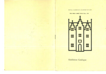
.TRANSCO.,.*-.TEST REPORT TR i:1.'O-.m*.' * - -N,--.'! - Q. .-.*'. .B--32,.- . ' %hs %,. . .'eh n . 7. ., . 3. . . - r, : . . , ., , . . . ; 4 .p , .*r- . , ,. P ,''w f.t U E.A,,9-- *- C ; * ': - -,.A- -(Qs);6ze*' 0.- .we'. L.- . . . .L.B:.-% W .-}.,.,.PLANE l b.ifj- h M '- d ., r.ee.OLUCh*CciY? -i A'g L[ A@.T EMBEDDED CONDUITSy , 9Yh4 s.:.:l'. -J9. . . . r. ne'.'( 'u: ['-repair6 dia, conduitIPVC cable)'.&:-'T, {*f'.,3 'g steel substrate- *y'U.''. .s. . . ,'. .yiW. s. at-Silicone E;astomer ,,z.;.TCO OO2 Medium Densitv7'?-. .9.30x4,, solid back tray anc PVCjacketed cablesa,.-:.,.removab!e plug'.'-.s.J. :/.3'.w;; .2: .-m.:.:7l.ic. -:.n m.'nrepair-t*-Q4I.: ' .?.;-'. . I*.*htNN,,. ---- 24 x 6,, solid back tray andHYPALON jacketed cab:esF .b?!.D *k?*20.C*r,!? O*.?.Q.LweM a r er . O s. ,:.9.:s.7;. . :,: .e. . - rec,. . %n,C.Oe.rsWci"'ra.F-jgst*26-m .' WMpio.s. -.-u-.'--.e concrete substrate'.'.4-2"dia. conduit (HYPALON cable) . . . -;. . - - . -. -g ir . -.', ,: --.t3:o'-.m'.It N:: . 2y-u-30"x 4' ladder back trayand PVC jacketed cables.x[ ; .o "Tc. .,.,w.,. r.r Q.e.rCc,0.,4,. ,4., . .m,.fc. - , . . . % .y-., .s.s c-soc.n.f,.;*'s.:.,;t-,s.-d.,., . , o,.,.,., ,.',q.s'*-. ,, . . .;.*, -x.: ,-. ; ; ".-,,.':.,e.t.z.s1s3 %.py y .x. :n-.o-, *.*t*.,:er . Q.- H se,';ew1ry. ' \ & ;. ;;. n- - -ini-.c.-1r y.,. . . . .r.,.,.s.,.-.-.*.,.; . . -**-*,-.tPLAN.:TCO OO2 MEDIUM DENSjTY SILICONEELASTOMER.-.m)-ta'LJ.
-.--TRANSCO.*TEST REPORT TR ill*.o.} N.i;*i'i?110tI!P:'i!i(Dilt U;T.iggg.'-* 1 *. e.g.Ie.r-r1,4 }, j f * -e.e47f.Lcables and trayfi:: : b. .;.t.i. H. , , .a . i. .j\dl.lfr-.!] t . .It D I Jm112u!,ij:J' a'4 ;mi.th j li.: ;.,n,.1--iu lp'ii wmeh lH. j u. . . 111i.!!d::ab :::., e.:i.t.'.i.,u,.u.os .3 .a.:. .y--.,.!ill!bE;iUliidiii:':DhlTCO OO2 MEDIUM CENSITYSILICONE ELASTOMER!n}Dii!i.Ho it, .e iilih!,"in;.!'1;}t: Ll ei!. h::w. l .slab1. .s. , :.::.J.:3 %U.::. ns sL h l.!. . . ::.- : '4.-a. . .-:-:. , . ' .:y -:3, - L .,:,.8. .s,s, . ; . , , . . . . . . . - . .-.: . .:. . . :.,.: . . -. -' .- .'-: : c. : '85:':: " :- - -: -* : -ce ,. :;?:.;3.:.'.sq.y.p . . . . , .f. f:. . . .Mg. ::. *.y.m.,. .2.ts,.":'- '.S)6N::5-'.L.-: :.w.S.::n :N,- u:! :"S."-: -v: :-:- -:n :.: J. :.-.-.,-.-repair.-.*.T.s:;i.t.i.:?i:i- i:i''. :.': : :%s.va.,Sa-*i:, . , .,.,.;: ., . .:g . : . ,- .e. : g,.3p. ,. .il:. kc.d, G.I. d M.II:hhfiE!!U. .i:.:., .1. .,.s.:. . . y:. . - - - -,. . . . ,.see DCTAIL 'A-, , , . :. ; . . , . . - . ,n. .:,,,.,t. -.--* #'0nutM!! NIO iSHNO .dUlfthreaded ro:(SECTION A-A'Oseal)azeyya.d m.:- : .;. l. . w.a . . . . . . , . ,. :.L.:.:. - . y-.: - - ja.9 g .neeAiR a REuOvAste etua. . .--. . .cab 1es*a.[},,,a.-Ji.'.:.,conduit.V.gjsealst.p ; . .J.a: ' p:. :.: , .&s .:,: , :, ::p.v.p.f.p. d. : .k.;, ' . " , , - g. .:J.i.:.-. . .i.,.c :.-: .] .c:-::.s.: : W e---- -.'. . .L.1 ;as. . .l-;'.;i!.r . - - -.-::.:.- .:0.:.,:.; -*{*3.;.e!.:3:ij.:.s.9. . . . i!!.-. E mn g f .: .:g.-:.t-- 53:pi;i ;tgcy.conduita4N i.1 8.p. , . . y: ,. ;g. . . ; : q . . '-;. -;- .''-:8-;r ys 3.-::.:.:g. p a ;,-: .- c :.;-.-: -r- - ;r . . ; f-:.p :s-s -1 -- -- :'::'.-:.;-: r';.:.,-: .v 5 --: . -'!5:-*: 3"II. -. , ;M'-,r- , .,M.:.w - .: -.4-f.;5.-:. ---. gin:W- -t .Ei . . -(:'gA,,.','''y.9. .2.- :p:m . .".[i(-iqs 25-s:( '-I .'.'. . . s.:.: .e W. FDETAll 'A*I-: .: eg. . .i; . : ,W. ga .n w , :;::3;.Ts j\ slab,1tQ 1.SECTION BBEMBEDDED CONDUlTS.
This report describes a three ho,ur fir,e and subsequent hose stream floor test of Transco #TCO-002 Mediun Density Silicone Elastomer insta'. led 12" deep in three electrical openings. The test was perforced in accordance with the ASTM E-119 time /te perature curve for three hours along with provisions--