Transcription
SMGr upReview ArticleSM DentistryJournalRecent Advancements in Diagnostic Aidsin Orthodontics - A ReviewAshish Kakadiya1, Ragni Tandon2, Aftab Azam2, Rohit Kulshrestha3* and MadhviBhardwaj4Consulting Orthodontist, Private Practice Surat, IndiaDepartment of Orthodontics and Dentofacial Orthopedics, Saraswati Dental College, India3Consulting Orthodontist, Private Practice, Mumbai, India4Department of Orthodontics and Dentofacial Orthopedics, Career PG Institute of Dental Sciences, India12Article InformationAbstractReceived date: Aug 05, 2017Accepted date: Aug 30, 2017Published date: Sep 05, 2017Every medical, dental and surgical procedure is solely based on the diagnosis of the underlying pathologyor disorder. In recent times there has been a tremendous advancement in scientific technology which has helpeddental practitioners all over the world. The use of computers in cephalometry has made it easier to view andmeasure various readings. Computer aided design and computer aided manufacturing have increased theaccuracy and quality of all dental materials. In the field of Orthodontics, there have been many advances. Thisarticle summarizes the recent advancements in diagnostic aids in Orthodontics which has helped revolutionizetreatment planning for the Orthodontic fraternity.*Corresponding authorsRohit Kulshrestha, ConsultingOrthodontist, Private Practice,Mumbai, India, Tel: 918601462462;Email: kulrohit@gmail.comDistributed under Creative CommonsCC-BY 4.0Keywords CBCT; Digital models;Diagnostic aidsIntroductionRecent advances in diagnostic aids address a special aspect of orthodontic diagnosis andtreatment planning that has become increasingly, important in our litigious society [1]. Successfulorthodontic treatment is dependent on the disciplined approach to record taking and diagnosis aswell as careful monitoring of progress in treatment, an inadequate record may be reflective of a poorstandard of treatment. The essentials for orthodontic records are a diagnostic report supported bystudy models, radiographs and photographs to establish the condition of the case before treatmentand to record progress during treatment. The problem oriented dental records significantly aidsin making the appropriate diagnosis. There is a significant improvement over the morphologicallyoriented diagnostic methods. The orthodontist’s job is to fit the pieces of the human craniofacialcomplex puzzle together. The expected outcome of this endeavour is a harmonious rearrangementthat is not only functional but also aesthetically pleasing. Clearly, this process must take into accountthe relationships in all three special axes. Oddly enough, while orthodontic treatment affects allthree dimensions, many of the current tools of diagnosis employ only a Two Dimensional (2D)representation of the patient. The two goals of orthodontic treatment (function and aesthetics) aredynamic entities. The statically occluded teeth are of limited value, though they might look good inthe form of a plaster cast. This is no different than the good-looking and the not so-good-looking,giving at least one pose to the photographer where they would appear aesthetically pleasing. In theabsence of a system where function and aesthetics can be assessed, both the orthodontist and thepatient are left to imagines or fantasize, rather than know, what the treatment outcome might be [2].The development of integrated 3D tools for diagnosis and treatment planning is one of the mostexciting developments in orthodontics as the specialty moves into the 21st century. The developmentof Computed Tomography (CT) and Three-Dimensional (3D) reconstruction in the 1970’s broughtabout a revolution in diagnostic radiology because cross-sectional imaging became possible. Bythe late 1980’s, 3D reconstruction algorithms were more optimized, and three-dimensional imagereformatting of standard 2D CT data (3D CT) became an often used tool to provide the radiologistand surgeon with readily recognizable images of complex anatomic structures such as the skull. Thesetechniques can exactly record and represent the life-size and shape of the object. Three-dimensionalvisualization with proper computer software and environment can be used for diagnosis, surgicalplanning, and simulation of operation. Developing such a computer system naturally combinesknowledge from medicine, dentistry, biomedical engineering and computer science [3].The practice of orthodontics has been transformed by the computer revolution of the 1990’s.Digital orthodontics has created a paradigm shift in practice management. The orthodontic practiceof the 1970’s and 1980’s can be seen in high contrast to the dynamic practices of the new millennium.With treatment records always at the orthodontist finger tips, orthodontic treatment has streamlinedand patient management has reached levels of sophistication never before possible. The internetand the development of high-speed communication modalities have enabled group practices, withmultiple locations, to access records in outlying locations electronically. This paradigm shift willOPEN ACCESSISSN: 2575-7776How to cite this article Kakadiya A, Tandon R, Azam A, Kulshrestha R and Bhardwaj M. RecentAdvancements in Diagnostic Aids in Orthodontics - A Review. SM J Dent. 2017; 3(2): 1016.
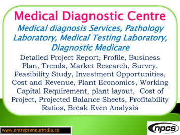
SMGr uppropel orthodontics well into the future [4]. As computers becamemore dynamic and reliable, orthodontic practitioners started to usecomputers unique strengths mostly to help in diagnosis and treatmentplanning. The key element in orthodontic treatment remains a skilledorthodontic specialist with an understanding of the biological andbiomechanical knowledge base that our specialty has painstakinglyacquired in more the 100 years of collective experience in treatmentand research [5]. The purpose of this article was to review the recentdiagnostic aids which help the Orthodontist in treatment planning.Cone Beam Computed TomographyCraniofacial CBCT were developed to counter some of thelimitations of conventional CT scanning devices. In craniofacialCBCT the object to be evaluated is captured as the radiation falls ontoa two-dimensional retractor. This simple difference allows a singlerotation of the radiation source to capture an entire region of interestas compared to conventional CT device where multiple slices arestacked to obtain a complete image. The cone beam also produces amore focused beam and considerably less scatter radiation comparedto conventional fan shaped CT devices (Figure 1).This significantly increases x-ray utilization and reduces thex-ray tube capacity required for volumetric scanning. It is said thatradiation exposure is 20% of conventional CT or equivalent to fullmouth peri-apical radiographic exposure [5].Advantages of CBCT Less cost Smaller in size Exposure chamber (head) is custom built and reduces the amountof radiation Images are comparable to conventional CT and are displayed asfull head view, as skull View or as regional components [6,7].Copyright Kulshrestha Rimage quality than by using higher settings. The patient’s effectiveexposure from a resultant CBCT is as low as 45 µSv to as high as 650µSv. Full mouth radiographs produce an exposure of 150 µSv and around trip from Tokyo to Paris is about 135 µSv of exposure. TheADA Council on scientific affairs recommends the use of techniquesthat would reduce the amount of radiation received during dentalradiography known as the ALARA principle (as low as reasonablyachievable). This includes taking radiographs based on the patientneeds, using the fastest film compatible with the diagnostic task,collimating the size of the beam to as close the size of the film asfeasible and using lead aprons and thyroid shields.Digital CephalometryIn 1922, Pacini described a rather primitive method forstandardization of radiographic imaging of the head. Herecommended positioning of the subject at a fixed distance of 2m fromthe x-ray source with a film cassette fixed to the head with a wrappingof gauze bandages [8,9]. Almost a decade later in 1931, Broadbentand Hoffarth (The United States and Germany) simultaneouslypublished their own methods of obtaining standardized lateral headradiographs. Their methods published in the Angle Orthodontistin 1937, introduced the field of cephalometry to the orthodonticcommunity.Cephalometry is a vital tool in orthodontic for evaluation ofcraniofacial complex, determination of morphology and growth,diagnosis of anomalies forecasting future relationship, planningtreatment and evaluating the results of growth and effects of treatment.Cephalometrics remains the only quantitative method that permitsinvestigation and examination of the spatial relationship betweenboth cranial and dental structures. The lateral cephalogram provideinformation regarding skeletal, dental, and soft tissue morphology aswell as relationship between these structures [10].Clinical Applications in OrthodonticsWith CBCT Orthodontists have many images that are notpossible with conventional radiographic measures. Impacted teeth and oral abnormalities Airway analysis Assessment of alveolar bone height and volume TMJ morphology Lateral and frontal Cephalogram views Skeletal views Facial analysis 3D review of dentition [8]Radiation ExposureCBCT provides three-dimensional images with up to four timesless radiation than a conventional CT scan. The resultant radiationis dependent on the settings used (Kvp and mA). The use of lowermA and/or collimation are some of the ways to reduce the amountof radiation the patient receives, but at the same time produces lowerFigure 1: CBCT Machine.Citation: Kakadiya A, Tandon R, Azam A, Kulshrestha R and Bhardwaj M. RecentAdvancements in Diagnostic Aids in Orthodontics - A Review. SM J Dent. 2017; 3(2): 1016.Page 2/8
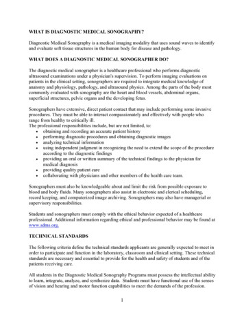
SMGr upCopyright Kulshrestha RThe use of lateral cephalograms in research includes Quantifying craniofacial parameters in individuals as well as apopulation of individuals Distinguishing normal from abnormal Comparing treated samples to untreated controls Differentiating populations as homogenous or mixed, andassessing the change of pattern over timeSince its advent in 1931, conventional cephalometry hasremained unchanged. Digital radiography has been accepted in thedental community, but high cost delayed their progress. Recentlywith the development of cost effective radiography (extra oral)and increased utilization of computers in orthodontics has madedigital cephalometric imaging a viable option. The paradigm shiftis occurring in orthodontics from the widely accepted film based todigital cephalometry. The methodology and various techniques forthe development of digital cephalograms are the same procedureas described earlier for digital radiography. To accept this scientificdescription various studies are being carried out to accept thereliability of these digital cephalograms (Figure 2).Rudolph et al. [11] compared the reliability of digital andconventional cephalometric radiographs in terms of landmarkidentification error. They concluded similar reproducibility andprecision in landmark identification using both direct digital andconventional lateral cephalometric head films. Heiko vesser et al.[12] studied and compared the radiation exposure and dose betweenconventional cephalometry and digital cephalometry. They concludedthat digital cephalometric radiography cuts the radiation dose inhalf compared with the conventional screen film technique andthat digital cephalometry is more advantageous than conventionalcephalometry in that perspective. Jia Kuing Liu et al. [13] studied theaccuracy of computerized identification of landmarks using variousangular and linear measurements. They concluded that computerizedidentification of certain landmarks is questionable and further studiesare needed to confirm their accuracy. Geelen et al. [14] studied thereproducibility of cephalometric landmarks on conventional film,hard copy and monitor displayed images obtained by a storagephosphor technique. They concluded that the there was no clinicallysignificant difference in landmark identification among the variousmethods.Factors to be considered before going to purchase software are Facility of integration of photographs and study models Windows based system available DICOM compatibility Lateral as well as posterio-anterior analysis should be possibleSoftwares Developed in IndiaDigicephMethod and 13 cephalometric analysis Developed by the center for Bio-Medical Engineering, IIT Delhiand Dept of Dental Surgery AIIMSDigital Imaging and Communications in Medicine (DICOM)American College of Radiology (ACR) and the NationalElectrical Manufacturers Association (NEMA) formed a jointcommittee in order to create a standard method for transmission ofmedical images and their associated information. DICOM definedinformation standardized not only for images but also for patients,students, reports and other data groupings. With the enhancementmade in DICOM (version 3.0) came the development and expansionof picture archiving and communication system and its interfacingmedical information systems.Digital Study ModelsStudy models have long been an essential part of the orthodonticprocess. They have traditionally been cast out of either plaster orstone and have served two main purposes: To provide information for diagnosis and treatment planning To provide a 3D record of the original malocclusion, any stagesduring correction and outcome of the treatment [15,16].Although study models are almost indispensable to theorthodontist, because they are cast in plaster or stone, they do have anumber of drawbacks in terms of:A plethora of software’s is available to clinician to choose from Vistadent Dolphin Quick ceph Dentofacial Planner Vixwin software Dr ceph Ortho plan Ceph x Orthoview cephFigure 2: Digital Cephalometry Image.Citation: Kakadiya A, Tandon R, Azam A, Kulshrestha R and Bhardwaj M. RecentAdvancements in Diagnostic Aids in Orthodontics - A Review. SM J Dent. 2017; 3(2): 1016.Page 3/8
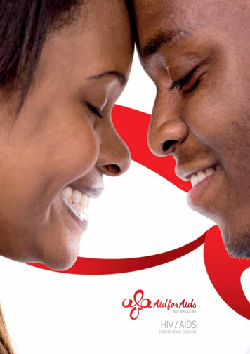
SMGr upCopyright Kulshrestha R Storage and retrieval;Manipulation of virtual models Diagnostic versatility; Transferability; Durability.Manipulation of virtual models is possible by using the Orthocadproprietary software and the virtual 3-D images are downloaded fromthe main server by the account holder.The introduction of digital models offers the orthodontist analternative to plaster study models routinely used. The digital studymodels overcome most of the drawbacks of plaster study modelsin addition to being the last component of a fully electronic patientchart (with digital photography and digital radiography already inuse). This computerized system opens a new realm of orthodonticdiagnosis (Figure 3).Procedure [17]There are two basic methods of producing digital study models:Destructive imaging: Removes part of a cast, little at a time, whileit is being imaged.Non-destructive imaging: uses structured light, laser light, orx-ray to an image while leaving the original cast intact.Two successful companies in producing high-quality 3-D modelsare: Orthocad [16,18] Geodigm [17]OrthocadThe Orthocad digital study model capture, assessment, andstorage system are used by approximately 10% of the orthodontists inUSA and Canada [16]. This software has been developed by CADENT(computer aided dentistry, Fairview, NJ, USA.). They use state ofthe art computer-aided design to optically scan in the model imagefrom a plaster equivalent. These are then presented to orthodontistthrough the patent orthocad software user interface that allows bothstructured and free manipulation of models in virtual space, and datacollection through a range of diagnostic tools.ProcedureStatic views from any perspectiveOrthocad three-dimensional browsers allow five simultaneousviews of models, thus allowing them to be examined from fivedifferent perspectives instead of having to rotate a particular view[16,18].Grab and drag manipulation in all planes of spaceThe jaw alignment tool enables the clinician to fine tune occlusionin case wax bite has distorted. The relationship of jaw can be recordedanteroposteriorly, between the limits of centric relation and centricocclusion and software remember this relationship.Occlusogram views highlighting occlusal contactsThe computer-generated occlusogram has a colour schemethat portrays tightness of contact points between jaws, essentiallysimulating wax bite width between articulating maxillary andmandibular teeth. The occlusogram changes if either jaw is movedlaterally or vertically [20]. Occlusal information is importantfor both initial diagnoses i.e. open versus deep bite, high versuslow mandibular plane angle and for assessment of jaw function.Furthermore, a comparison of pre and post treatment occlusogramscan help evaluate treatment methodology and stability of results.Transverse and vertical sectioningUnlike plaster procedures, digital models can be sectioned anytime in the sagittal or transverse plane. This may shed a new light ondental and skeletal asymmetries and can help pinpoint skeletal anddental midlines.DiagnosticsMeasurements are made with a virtual caliper and automaticallystored. Various analysis like tooth width measurements, spaceassessment, Moyers and Tanaka-Johnston prediction, BoltonHigh-Quality Impressions: It is essential to take high-qualityimpressions and a bite registration. The impressions can be takenin high-quality alginate, polyvinyl silicone or polyether material.The aim is to produce impressions that are extremely accurate anddimensionally stable. The alginate impressions are then sanitizedwrapped in lamp paper towel and placed in sealable plastic bagsto ensure retention of moisture. The impressions are then shippedand in a case of longer periods for shipping and storage polyethermaterials may be used.Scanning of impressionsWhen the impressions are received, they are converted to plasterequivalents and optically scanned without destruction of plasterequivalent into the Orthocad computer system. Then the patient’svirtual 3-D models are downloaded to your computer [19].Figure 3: Digital Study Models (Orthocad).Citation: Kakadiya A, Tandon R, Azam A, Kulshrestha R and Bhardwaj M. RecentAdvancements in Diagnostic Aids in Orthodontics - A Review. SM J Dent. 2017; 3(2): 1016.Page 4/8
SMGr upanalysis, arch width measurements can be made. The virtual caliperallows any section of the model to be measured within 100 microns(0.1 mm). These are then calculated along with arch form and archsize to give space discrepancy. All contact points and measurementsare saved with Individual patient folder into which the digital modelis also incorporated for future references. They can also be e-mailed tofellow dentists and other health professionals along with notes, views,and measurements.Advantages It is a simpler and more effective way of measuring and storingdata received from a virtual model Ease of storage and integration into the patient’s digital file alongwith digital photographs, X-ray, and clinical notes Retrieval and viewing along with the patient’s other clinical datacan be done at chair side Can be transferred to other healthcare personnel via prints ore-mail attachmentDisadvantages Virtual models cannot be mounted and articulated in reference topatients TMJ functions, although jaw alignment tool comes closeto this The models are expensive and cost about 36 per set of modelsand shipping costs about 55 Time-consuming The main reason why only 10% of orthodontists use it is that thelegal acceptance of digital study models is still questionableOrthocad could revolutionize the way in which study models areviewed, managed and stored. The ability to rotate, tilt and sectionmodels, and hold them in any position, allows for detailed analysis,with added advantage of bringing models up instantly with otherclinical information, chair side. In an era of electronic patient records,when all patient information is stored digitally, commercially availabledigital model systems, such as orthocad will soon be the norm.GeodigmCopyright Kulshrestha Rdata storage. Using models, the clinician can move, rotate, or zoomin any plane or orientation. Point to point, Bolton analysis, and curvelength measurement can easily be made by pointing and clickingthe mouse. Colour bite mapping features permit analysis of occlusalrelationships, 3D colour coded map demonstrates occlusal contentbetween arches. In addition, there is an articulation feature whichallows the clinician to set the centre of rotation. The articulationprocess can be animated and viewed as occlusal contact happens.One of latest developments is e-plan, which simulates multipletreatment plans to help determine most effective treatment. Thisalso allows simulation of rotation movements and allows patient toview their own teeth from malocclusion to a post treatment view. Theopportunities for 3D technology are endless. These new software’s areproviding new efficiency for doctors and enhanced patient care.UltrasonographyThe phenomenon perceived a sound is the result of periodicchanges in pressure in the air against the eardrum. The periodicity ofthese changes lies anywhere between 1500 and 20000 cycles per second(hertz, Hz). By definition, ultrasound has a periodicity of greater than20 kHz. Thus it is distinguished from other mechanical waveformssimply by having a vibratory frequency greater than audible range.Diagnostic Ultrasonography, the clinical application of Ultrasound,employs vibratory frequency in the range of 1 to 20 MHz. [21]Scanners used for sonography generate electrical impulses that areconsidered with high-frequency sound waves by a transducer, whichis a device that converts one form of energy to another, in this case,sonic energy to electrical energy (Figure 4). The most important partof the transducer is a thin piezoelectric crystal or material made up ofa great number of dipoles arranged in a geometric pattern. A dipole isa distorted molecule with a positive charge on one side and negativecharge on the other. Currently most widely used piezoelectric materialis Lead Zirconate. The electrical impulse generated by scanner causesdipoles within crystal to realign themselves within electric field andthus suddenly change a series of vibration that produces sound wavesthat are transmitted into tissue being examined [22].As ultrasound beam passes through or interacts with tissues ofdifferent acoustic impedance, it is attenuated by a combination ofabsorption, reflection, refraction, and diffusion. Sonic waves thatare reflected back (echoes) towards transducer causes a change inGeodigm E-models are constructed through a proprietary laserscanning process, that digitally maps the geometry of patient’sanatomy into a high dimensional 3-D image, with an accuracy of0.1 mm. Scanners project a laser stripe on the surface of the cast anduse digital cameras to analyze distortions in the stripe. The cast isoriented in all axes to expose for scanning. This produces 3D verticesthat are connected to thousands of triangles to form the 3D image.The software then displays the e-model on the computer screen bygiving colour shades, to each triangle based on its orientation to adigital light source. The result is a 3D image, which can be viewed,measured or manipulated on screen as if it is cast in your hand [17].Clinical Management of ModelsThe orthodontist sends the impressions and bite registration toGeodigm and plaster cast is made which is scanned to an e modeland articulated. The model can be then downloaded from the mainserver. A copy is maintained on Geodigm server for the security ofFigure 4: Ultrasonography Process.Citation: Kakadiya A, Tandon R, Azam A, Kulshrestha R and Bhardwaj M. RecentAdvancements in Diagnostic Aids in Orthodontics - A Review. SM J Dent. 2017; 3(2): 1016.Page 5/8
SMGr upthickness of the piezoelectric crystal, which in turn produces anelectric signal that is amplified, processed and then displayed on amonitor. On this system, transducer serves both as receiver andtransmitter. High-resolution systems may offer a slight thicknessof 0.5 mm or less and a lateral resolution of 1 mm. Techniquescurrently in use permit echoes to be processed at a sufficiently rapidrate to allow perception of motion. This is called real time imaging[23]. In contrast to x-ray imaging, where an image is produced bytransmitted imaging here it is produced by reflectors portion of thebeam. The fraction of the beam that is reflected back to the transduceris dependent on the acoustic impedance of tissue, which is a productof its density (and thus the velocity of sound through it) and beamangle of incidence. Because of its acoustic impedance, a tissue hasan internal echo pattern that is characteristic. The changes in echopattern are correlated with pathologic changes in tissue, thus notknowledge of only technique, but also the anatomy of the structureis a must.Applications (In Head and Neck) [24]Mainly used in imaging of Lymph nodes Post surgery, edema, and hematoma Eye, thyroid gland, and parotid gland Submandibular salivary gland To demonstrate thickness of masticatory mucosa Demonstrate displacement of soft tissue under denture by forcesof occlusionComparison of Tongue Functions between Matureand Tongue-Thrust Swallowing [25]Tongue functions during swallowing are of interest to manyorthodontists. In normal deglutition, the tip of the tongue rests on thelingual part of the dentoalveolar area, the contraction of the perioralmuscles is minimal during deglutition, the teeth are in momentarycontact during swallowing, and there is neither a tongue thrust nor aconstant forward posture. Several methods for evaluation of tonguemovements, such as radio-cinematography, electromyography,and electromagnetic articulography, have been used in previousstudies. Electropalatography and electromagnetic articulographyare not suitable for examining normal tongue function because itis difficult for subjects to swallow normally with receiver coils andwires attached to their palates or tongues. X-ray cinematographyand computerized tomography have the disadvantage of radiationexposure. Magnetic resonance imaging is not suitable for examiningswallowing movements because of its high cost and long acquisitiontime [26]. Ultrasonography has the advantages of being non-invasive,rapid, easily repeatable, and relatively inexpensive. Ultrasonographyhas been used in many studies for static imaging of the oral cavity (e.g.for studying tongue morphology and for diagnosis of sialolithiasis,cysts, and tumours). Dynamic ultrasound investigation of tonguemovement through sub mental scanning has been described by manyresearchers.A major obstacle of these previous dynamic ultrasound studieswas that they used direct transducer-skin coupling scanning toCopyright Kulshrestha Robserve tongue movements, this causes various artifacts resultingin inaccurate measurements of tongue movements. A cushionscanning method provides a solution to these problems. With acushion scanning system that consists of a cushion device, a headsupport, a probe holder, and a head position recording device, thetongue dynamic can be correctly recorded and measured. Therefore,noninvasive real-time B M-mode ultrasonography with CST hasbecome the state-of-the-art tool to study tongue morphology andobserve tongue functions such as swallowing and speech.Ultrasound Imaging of Condylar Motion [27]Imaging of the temporomandibular joint in an effort tounderstand normal and abnormal function continues to be achallenge. The principal methods currently used to image the jointin the sagittal view are x-rays, magnetic resonance imaging, andarthroscopy. The main disadvantage of x-rays is that they provide astatic view while exposing the surrounding structures to radiation.With magnetic resonance imaging, the patient’s head position isabnormal, which can influence mandibular motion. It is a costlyprocedure and often requires the patient to travel to a special facility.Arthroscopy involves surgical invasion of the joint with attendantsurgical risks as well as the significant likelihood of altering normalfunction by its presence. Ultrasound imaging has been recognized forsome time as having several important advantages: it does not requirespecial facilities and thus has the potential to become available in anorthodontic office, and it can be used to view the joint in a continuumwithout invasion, discomfort, alteration of the patient’s normal headposture, or interference with condylar motion.Audio frequencies greater than 1600 Hz (cycles per second) areconsidered ultrasonic. An ultrasonic sound wave passing through thetissue will have a portion of the sound wave reflected on transitingdissimilar tissues. This reflected energy is returned to the ultrasonicemitting device (transducer) where the location of the interface isdetermined, and an appropriate image is produced representingthe interface contours. In earlier studies, ultrasonic transducershave been placed at various parts of the skin surfaces related to thetemporomandibular joint area. This produced nonconventionalimages of the joint from the frontal, superior, or both aspects. RecentlyHirt and Knupfer obtained images of the temporomandibular joint inthe more conventional sagittal plane. These were images of the jointsof cadavers. Until now, obtaining conventional (sagittal) images ofthe temporomandibular joint via sonography has been limited forseveral reasons. Ultrasound is unable to penetrate the relatively largemass of bone overlying the joint, and the size of the transducer hasprevented its strategic placement in order to produce conventionalsagittal images [27].Three-dimensional ultrasonographyThree-dimensional ultrasound imaging is a new technologythat presents views of the fetal face with greater clarity than theconventional two-dimensional imaging described previously.
The practice of orthodontics has been transformed by the computer revolution of the 1990's. Digital orthodontics has created a paradigm shift in practice management. The orthodontic practice . of the 1970's and 1980's can be seen in high contrast to the dynamic practices of the new millennium.