Transcription
Product Change Notification / SYST-03YDHP471Date:04-Feb-2021Product Category:Bluetooth ModulePCN Type:Document ChangeNotification Subject:Data Sheet - RN4870/71 Bluetooth Low Energy Module Data SheetAffected CPNs:SYST-03YDHP471 Affected CPN 02042021.pdfSYST-03YDHP471 Affected CPN 02042021.csvNotification Text:SYST-03YDHP471Microchip has released a new Product Documents for the RN4870/71 Bluetooth Low Energy Module Data Sheet of devices. If you areusing one of these devices please read the document located at RN4870/71 Bluetooth Low Energy Module Data Sheet.Notification Status: FinalDescription of Change:1) Added new description for VDD IO pins in Table 1-2.2) Added labeling information of Brazil for RN4871 module.3) Added Section 11.1.3 “Approved Antennas”, Section 11.2.3 “Approved Antennas” and Section 11.8 “Brazil”.4) Updated Section 11.2.1 “Labeling and User Information Requirements”, Section 11.3 “Europe” and Section 11.7 “China”.Impacts to Data Sheet: NoneReason for Change: To Improve ManufacturabilityChange Implementation Status: CompletePage 1 of 2
Date Document Changes Effective: 04 Feb 2021NOTE: Please be advised that this is a change to the document only the product has not been changed.Markings to Distinguish Revised from Unrevised Devices: N/AAttachments:RN4870/71 Bluetooth Low Energy Module Data SheetPlease contact your local Microchip sales office with questions or concerns regarding this notification.Terms and Conditions:If you wish to receive Microchip PCNs via email please register for our PCN email service at our PCNhome page select register then fill in the required fields. You will find instructions about registering forMicrochips PCN email service in the PCN FAQ section.If you wish to change your PCN profile, including opt out, please go to the PCN home page select loginand sign into your myMicrochip account. Select a profile option from the left navigation bar and makethe applicable selections.
SYST-03YDHP471 - Data Sheet - RN4870/71 Bluetooth Low Energy Module Data SheetAffected Catalog Part Numbers 71-V/RM130RN4871-V/RM140RN4871U-V/RM118Date: Thursday, February 04, 2021
RN4870/71Bluetooth Low Energy ModuleFeatures Qualified for Bluetooth SIG v5.0 Core SpecificationCertified to FCC, ISED, CE, KCC, NCC and SRRCOn-Board Bluetooth Low Energy (BLE) StackASCII Command Interface API Over UARTScripting Engine for Hostless OperationCompact Form Factor – The RN4870/71 familycomes in four different sizes, from 6 mm x 8 mmto 12 mm x 22 mm:- RN4870: 12 mm x 22 mm- RN4871: 9 mm x 11.5 mm- RN4870U: 12 mm x 15 mm- RN4871U: 6 mm x 8 mm Beacon Private Service for Beacon Services UART Transparent Service for Serial DataApplications Remote Configuration Over-the-AirOperational Operating Voltage: 1.9V to 3.6V (3.3V typical) Temperature Range:- -20 C to 70 C (Normal)- -40 C to 85 C (Industrial) Supports UART Up to Three Pulse-Width Modulation (PWM)Outputs (only for RN4870)RF/Analog Features ISM Band 2.402 to 2.480 GHz OperationChannels: 0-39RX Sensitivity: -90 dBmTX Power: 0 dBmRSSI MonitorMAC/Baseband/Higher Layer Features Secure AES128 Encryption GAP, GATT, SM, L2CAP and Integrated PublicProfiles Customer Can Create up to Five Public and FourPrivate Services Keyboard I/O Authentication Software Configurable Role as Peripheral orCentral and Client or Server 2016-2021 Microchip Technology Inc.Antenna Options Chip Antenna Range based on Open AirMeasurements and Phone Module Connection:- RN4870: Up to 50m- RN4871: Up to 10m External Antenna Connection via RF Pad(RN4870U/RN4871U)Applications Health/Medical DevicesSports Activity/Fitness MetersBeacon ApplicationsInternet of Things (IoT) Sensor TagRemote ControlWearable Smart Devices and AccessoriesSmart Energy/Smart HomeIndustrial ControlDS50002489E-page 1
RN4870/71Table of Contents1.0 Device Overview . 32.0 Specifications . 113.0 Interface Pins . 134.0 Physical Dimensions and Attributes. 155.0 Application Reference Circuits . 256.0 ASCII Command API . 297.0 Supported Services. 318.0 Antenna Characteristics . 339.0 Timing Characteristics. 3510.0 Ordering Information . 3711.0 Regulatory Approval. 39Appendix A: Revision History. 45The Microchip Website . 47Customer Change Notification Service . 47Customer Support . 47Product Identification System . 49TO OUR VALUED CUSTOMERSIt is our intention to provide our valued customers with the best documentation possible to ensure successful use of your Microchipproducts. To this end, we will continue to improve our publications to better suit your needs. Our publications will be refined andenhanced as new volumes and updates are introduced.If you have any questions or comments regarding this publication, please contact the Marketing Communications Department viaE-mail at docerrors@microchip.com. We welcome your feedback.Most Current Data SheetTo obtain the most up-to-date version of this data sheet, please register at our Worldwide Website at:http://www.microchip.comYou can determine the version of a data sheet by examining its literature number found on the bottom outside corner of any page.The last character of the literature number is the version number, (e.g., DS30000000A is version A of document DS30000000).ErrataAn errata sheet, describing minor operational differences from the data sheet and recommended workarounds, may exist for currentdevices. As device/documentation issues become known to us, we will publish an errata sheet. The errata will specify the revisionof silicon and revision of document to which it applies.To determine if an errata sheet exists for a particular device, please check with one of the following: Microchip’s Worldwide Website; http://www.microchip.com Your local Microchip sales office (see last page)When contacting a sales office, please specify which device, revision of silicon and data sheet (include literature number) you areusing.Customer Notification SystemRegister on our website at www.microchip.com to receive the most current information on all of our products.DS50002489E-page 2 2016-2021 Microchip Technology Inc.
RN4870/711.0DEVICE OVERVIEW1.1OverviewTable 1-1 shows the various options for packaging andfeatures available in the RN4870/71 family. Table 1-2provides the description of the pin functions for all themodules in the RN4870/71 family. Figure 1-1 throughFigure 1-4 show the pinouts for the different modules.The RN4870/71 BLE module integrates Bluetooth 5.0baseband controller, on-board Bluetooth stack, digitaland analog I/Os and RF power amplifier into onesolution.TABLE 1-1:RN4870/71 FAMILYOn-BoardAntennaShieldingNumber ofPinsRN4870-V/RMXXXYesYes3312 mm x 22 mm-20 C to 70 CRN4870U-V/RMXXXNoNo3012 mm x 15 mm-20 C to 70 CRN4871-V/RMXXXYesYes169 mm x 11.5 mm-20 C to 70 CRN4871U-V/RMXXXNoNo176 mm x 8 mm-20 C to 70 CRN4870-I/RMXXXYesYes3312 mm x 22 mm-40 C to 85 CRN4871-I/RMXXXYesYes169 mm x 11.5 mm-40 C to 85 CPart Number(1)Note 1:DimensionsOperatingTemperature RangeThe last three digits in P/N indicate the firmware version. At the time of publication, the latest firmwareversion is 1.28. Ensure to check the product webpage for the latest part number and firmware version.TABLE 1-2:PIN DESCRIPTIONRN4870U RN4870 RN4871U RN4871NameTypeDescription—1——GNDPower Ground reference.—2——GNDPower Ground reference.131213GNDPower Ground reference.241114VBATPower Positive supply input. Range: 1.9V 3.6V.——10—BK INPower Buck power supply input,Can be connected to the VBAT pin,Connect to 10 µF low-ESR ceramic capacitor, Voltage range: 1.9V to 3.6V.35——P2 2D I/O GPIO,PWM1 (only for RN4870),Default: Input; pulled high.46——VDD IOPower I/O positive supply. Do not connect.Ensure VDD IO and MCU I/O voltage are compatible.57——VDD IOPower I/O positive supply. Do not connect.Ensure VDD IO and MCU I/O voltage are compatible.68——ULPC OPower 1.2V ULPC LDO output,Used for diagnostic purposes,Do not connect to any pin or device,For measurement, connect a bypass 1 µF capacitor to ground.79——P2 3D I/O GPIO,PWM2 (only for RN4870),Default: Input; pulled high.810——BK OPower 1.55V Buck power supply output for diagnostic purpose.Do not connect.Legend: Pin Type Abbreviations: 2016-2021 Microchip Technology Inc.A AnalogD DigitalI/O Input/OutputI/p InputO/p OutputDS50002489E-page 3
RN4870/71TABLE 1-2:PIN DESCRIPTION (CONTINUED)RN4870U RN4870 RN4871U RN4871NameTypeDescription——136P1 6DConfigurable pin. Refer to Section 1.2 “ModuleConfiguration” for details. When connected to hostMCU, set the pin connected to pin P1 6 in eitherhigh-impedance or drive pin low during firmwarestart-up (approximately 22 msec).——145P1 7DConfigurable pin. Refer to Section 1.2 “ModuleConfiguration” for details.9111515P2 7D O/p UART TX IND output pin. Provides indication ifRN4870 is transmitting to host MCU over UART.Pulled low before UART TX begins and pulled highafter UART TX is over.1012——P1 1D I/O GPIO; default: Input; pulled high,A I/p AD9,Configured as the BLEDK STATUS1 IND pin bydefault.111323P1 2D I/O GPIO; default: Input; pulled high,A I/p AD10; I2C SCL pin.121434P1 3D I/O GPIO; default: Input; pulled high,AD11; I2C SDA pin.1315811P0 0D I/O GPIO; default: Input; pulled high,AD0,Configured as the UART CTS pin by default.1416——P1 0D I/O GPIO; default: Input; pulled high,AD8,Configured as the BLEDK STATUS2 IND pin bydefault.151769P3 6D I/O GPIO; default: Input; pulled high (only for RN4870),Configured as the UART RTS pin by default.16181616P2 0D I/p1719——P2 4D I/O GPIO; default: Input; pulled high.1820——NC—1921710RST ND I/pModule Reset; active-low; Internally pulled high.202257UART RXD I/pUART data input.212348UART TX D O/p UART data output.2224——P3 1D I/O GPIO; default: Input; pulled high,Configured as RSSI IND pin by default; SPI NCS Bus.2325——P3 2D I/pGPIO; default: Input; pulled high,Configured as the LINK DROP pin by default; SPI MISO pin.2426——P3 3D I/pGPIO; default: Input; pulled high,Configured as the UART RX indication pin by default;SPI MOSI pin.2527——P3 4D I/pGPIO; default: Input; pulled high,Configured as the PAIRING KEY pin by default; SPI SCLK pin.Legend: Pin Type Abbreviations:DS50002489E-page 4A AnalogD DigitalSystem configuration input;1: Application mode0: Test mode/Flash update/EEPROM configurationDefault: Input; pulled high.No connection.I/O Input/OutputI/p InputO/p Output 2016-2021 Microchip Technology Inc.
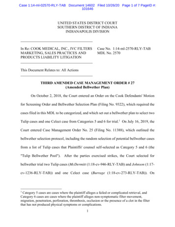
RN4870/71TABLE 1-2:PIN DESCRIPTION (CONTINUED)RN4870U RN4870 RN4871U RN4871NameTypeDescription2628——P3 5D I/O GPIO; default: Input; pulled high,A I/p LED1; provides indication whether the module is on/off.2729——P0 7D I/O GPIO; default: Input; pulled high,Configured to the LOW BATTERY INDICATOR pinby default.2830912P0 2D I/O AD2,LED0: Provides indication whether the module is inOn/Off mode.2931172GNDPower Ground reference.—32——GNDPower Ground reference.30—1—BT RF—33——GNDLegend: Pin Type Abbreviations:FIGURE 1-1:A AnalogA I/OExternal antenna connection (50 Ohms). Only forRN4870U and RN4871U. No connection for RN4871.Power Ground reference.D DigitalI/O Input/OutputI/p InputO/p OutputPIN DIAGRAM – RN4870UTop ViewGND 1VBAT 2P2 2 3VDD IO 4VDD IO 5ULPC O 6P2 3 7BK O 8P2 7/TX IND 9P1 1 10P1 2 11P1 3 12Bottom View30 BT RFGNDP0 2/LEDP0 7P3 5P3 4P3 3P3 2P3 1UART TXUART RXTP-3TP-1TP-2TP-3 VCC RFTP-1 VCC PATP-2 CLDO OP0 0/CTSP1 0P3 6/RTSP2 0/MODEP2 4NCRST N1314151617181929282726252423222120130 2016-2021 Microchip Technology Inc.DS50002489E-page 5
RN4870/71FIGURE 1-2:PIN DIAGRAM – RN4870Top View12GNDVBATP2 2VDD IOVDD IOULPC OP2 3BK OP2 7/TX INDP1 1P1 2P1 33456789101112131433 GND32 GND31302928272625242322GNDP0 2/LEDP0 7P3 5P3 4P3 3P3 2P3 1UART TXUART RX331TP-3TP-1TP-2TP-3 VCC RFTP-1 VCC PATP-2 CLDO OP0 0/CTSP1 0P3 6/RTSP2 0/MODEP2 4NCRST N15161718192021GNDGNDBottom ViewFIGURE 1-3:PIN DIAGRAM – RN4871UBottom View4321UART TXP1 3P1 2BT RFTop View5678917 GND1716 P2 015 P2 714 P1 7VCC RF TP-2VCC PA TP-3TP-1TP-2 TP-4TP-3TP-5TP-1 CLDO OTP-4 ULPC OTP-5 BK OBK INVBATGNDP1 610111213UART RXP3 6RST NP0 0P0 21DS50002489E-page 6 2016-2021 Microchip Technology Inc.
RN4870/71FIGURE 1-4:PIN DIAGRAM – RN48717RS 9LHZ1&%RWWRP 9LHZ *1' 3 B 3 B 3 B 9% 73 B *1' 3 B 8 57B7;3 B TP-3TP-2%.B2 73 TP-1&/'2B2 73 TP-473 9&&B3 73 9&&B5)73 8/3&B2TP-532B 567B1 3 B 8 57B5;3 B 16 2016-2021 Microchip Technology Inc.DS50002489E-page 7
RN4870/711.2Module ConfigurationThe GPIO pins of the RN4870 and RN4871 modulescan be configured for different functions using theASCII command interface. Table 1-3 shows the variouspins in the RN4870/71 module that are available forconfiguration and their default configuration settings.Table 1-4 provides details on each available function.TABLE 1-3:Table 1-5 shows the status of the module as indicatedby the Status 1 and Status 2 indication pins. Table 1-6shows the details of test pads that are present on thebottom side of the module, used for diagnosticpurposes during testing. Figure 1-5 shows all the keyelements of the module.CONFIGURABLE PINS AND DEFAULT FUNCTIONS IN THE RN4870 AND RN4871Pin NameAvailable inDefault FunctionRN4870RN4871P0 7x—Low Battery IndicationP1 0x—Status 2P1 1x—Status 1P2 2x—NoneP2 4x—NoneP3 1x—RSSI IndicationP3 2x—Link DropP3 3x—UART RX IndicationP3 4x—Pairing KeyP3 5x—NoneP1 2xxNoneP1 3xxNoneP1 6—xUART RX IndicationP1 7—xNoneTABLE 1-4:CONFIGURABLE FUNCTIONS AND DESCRIPTIONSFunction NameDescriptionLow Battery IndicationPin output goes low when the VDD is below a specified level. To set the thresholdlevel, change the EEPROM settings.Status 1Use this indication pin along with the Status 2 pin to indicate the current status ofthe module. Refer to Table 1-5 for details of the status indication.Status 2Use this indication pin along with the Status 1 pin to indicate the current status ofthe module. Refer to Table 1-5 for details of the status indication.RSSI IndicationUse this indication pin to indicate the quality of the link based on the RSSI level.If the RSSI level is lower than the specified threshold value, then the RSSIindication pin goes low. Set the threshold for the RSSI link quality in EEPROM.Link DropWhen the RN4870/71 is connected to a remote device, the host MCU can usethe Link Drop pin to force the module to disconnect the link and enter Shutdownstate. The pin needs to be pulled low for at least 10 ms.UART RX IndicationUse this pin to enable communication with the UART when the module is in LowPower mode. When not in Low-Power mode, the module runs on a 16 MHzclock. If Low-Power mode is enabled on the module by using the command,SO,1, the module runs on a 32 kHz clock, thus reducing power consumption.However, in Low-Power mode, the host MCU cannot communicate with themodule via the UART since the UART is not operational. If the user intends toprovide data or commands via UART in the Low-Power mode, then the UARTRX Indication pin must be pulled low and the user needs to wait for at least fivemilliseconds before sending the data. Pulling the UART RX Indication pin lowallows the module to operate the 16 MHz clock and to enable UART.DS50002489E-page 8 2016-2021 Microchip Technology Inc.
RN4870/71TABLE 1-4:CONFIGURABLE FUNCTIONS AND DESCRIPTIONS (CONTINUED)Function NameDescriptionPairing KeyWhen the RN4870/71 is connected to a remote device, the host MCU can usethe Pairing Key pin to force the module to disconnect the link and go back toStandby state. The pin must be pulled down for at least 160 ms.RF Active IndicationUse this indication pin to indicate that the module is currently performing anactive transmission and receiving BLE data.TABLE 1-5:STATUS INDICATION PINSStatus 1Status 2HighHighPower-onHighLowStandby stateLowLowConnection establishedLowHighData session open (Transparent UART)TABLE 1-6:StateTEST POINTS ON THE BOTTOM -3VCC PA1.55V RF PA LDOTP-2TP-2TP-1TP-5CLDO O1.2V CLDO OutputTP-3TP-3TP-2TP-2VCC RF1.2V RF LDO Output——TP-4TP-4ULPC O1.2V ULPC LDO Output——TP-5TP-1BK O1.55V Buck Reg OutputFIGURE 1-5:DescriptionBLOCK DIAGRAM OF THE RN4870/71RN4870/RN4871AntennaHostController(Ext. MCU)IOTPeripheralDeviceSPIMatchingUART8051 (16 MHz)I 2C32 KB ROMPWM24 KB SRAMADC-12bFlash 256 KBEventCounterDMA, WDT,NMI, IRQPeripheralsBT RF BluetoothBLEBasebandand RF32 MHzCrystalPMU/MMBand GapAES 128MCUPORRTC512BRet-RAM32 kHzROSCGPIO PORTLDO0 3*Always On IO Pad on ModuleMCU/GPIO/LED 2016-2021 Microchip Technology Inc.DS50002489E-page 9
RN4870/71NOTES:DS50002489E-page 10 2016-2021 Microchip Technology Inc.
RN4870/712.0SPECIFICATIONSTable 2-1 provides the general specifications for themodule. Table 2-2, Table 2-3 and Table 2-4 provide theelectrical characteristics and the current consumptionof the module.TABLE 2-1:GENERAL SPECIFICATIONSSpecificationDescriptionStandard ComplianceBluetooth 5.0Frequency Band2.402 to 2.480 GHzModulation MethodGFSKMaximum Data Rate (Transparent UART)10 kbps (iOS 9)AntennaCeramicInterfaceUART, AIO, PIOOperating Range1.9V to 3.6VSensitivity-90 dBmRF TX Power0 dBmOperating Temperature Range for RN4870-I and RN4871-I Modules-40 C to 85 COperating Temperature Range for RN4870-V and RN4871-V Modules-20 C to 70 CStorage Temperature Range-40 C to 125 COperating Relative Humidity Range10% to 90%Storage Relative Humidity Range10% to 90%Moisture Sensitivity Level2TABLE 2-2:ELECTRICAL VVIL Input Logic Levels LowVSS—0.3 VDDVVIH Input Logic Levels High0.7 VDD—VDDVVOL Output Logic Levels LowVSS—0.2 VDDVVOH Output Logic Levels High0.8 VDD—VDDV63——nsPull-up Resistance344874k Pull-Down Resistance294786k Supply Voltage (VDD)I/O Voltage LevelsResetReset Low DurationInput and Tri-State Current with 2016-2021 Microchip Technology Inc.DS50002489E-page 11
RN4870/71CURRENT CONSUMPTION(1)TABLE 2-3:ParameterMin.Typ.Max.UnitsTX Mode Peak Current at VDD 3V, TX 0 dBm, Buck Mode—10 at 25 C13 at 75 C/ 85 CmARX Mode Peak Current at VDD 3V, Buck Mode—10 at 25 C13 at 75 C/ 85 CmALow-Power Mode Current(2)—60 at 25 C—µAShutdown Low-Power Mode1—2.9µASupply CurrentNote 1:2:The current measurements are characterized across a sample of the RN4870/71 module at room temperature ( 25 C), unless otherwise noted.For more details on Low-Power mode, refer to the “RN4870/71 Bluetooth Low Energy Module User’sGuide” (DS50002466).TABLE 2-4:CURRENT CONSUMPTION DURING APPLICATION MODETest ModeAdvertising(1,2,3)Connected(1,2,4)Note 1:2:3:4:Interval(ms)Average Current Consumption201.061 mA50505 µA100298 µA500113 µA100089 µA18.752.23 mA502.13 mA1002.10 mA50083 µA100080 µAThese measurements are done at an operating temperature of 25 C at 3.3V and are characterizedacross a sample of the RN4870/71 module.Measurements taken with Version 1.18 firmware loaded onto the module.The advertising packet data payload is approximately 15 bytes in length.The amount of data being transmitted between two peer devices can affect the average current measured.The average current measurements are done with only the necessary Bluetooth packets beingexchanged to keep the connection active at the stated interval.DS50002489E-page 12 2016-2021 Microchip Technology Inc.
RN4870/713.0INTERFACE PINSFigure 3-1 shows the power scheme using a 3.3Vlow-dropout regulator to the RN487X and a host MCU.This scheme ensures that the same voltage is used forboth the module and the MCU.FIGURE 3-1:Figure 3-1 also shows the basic UART connections tothe host MCU.Figure 3-2 shows the recommended connections forrunning the RN4870/71 on a coin cell battery.POWER SCHEMERN4870/71/70UReset ICSystem ConfiguratorNote 1:2:3:Ensure VDD IO and MCU VDD voltages are compatible.Control and Indication ports are configurable.To implement low-power operation, enable the UART RX INDpin and connect to ground.RN4871UReset ICResetSystem Configurator 2016-2021 Microchip Technology Inc.Note 1:2:3:4:5:Ensure VDD IO and MCU VDD voltages are compatible.Control and Indication ports are configurable.10 µF (X5R) and 330 Ohm resistor are required for RN487X.BK IN connects to VBAT for RN4871U.To implement low-power operation, enable the UART RX INDpin and connect to ground.DS50002489E-page 13
RN4870/71FIGURE 3-2:RN4870/71 COIN CELL POWER SCHEMERN4870/71Reset ICNote 1:2:3:ResetApplication includes ADC, PWM (RN4870) and I2C bus interface.BK IN connection is needed only for RN4871U.To implement low-power operation, enable the UART RX IND pin and connect to ground.The Configuration pins on the RN4870 can also beconfigured through a Windows based User Interface(UI) configuration tool, BLEDK3.DS50002489E-page 14 2016-2021 Microchip Technology Inc.
RN4870/714.0PHYSICAL DIMENSIONS ANDATTRIBUTES4.1RN4870 ModuleFigure 4-1 shows the physical dimensions of the RN4870module. Figure 4-2 illustrates the recommended PCBlayout and Figure 4-3 shows the recommendedmounting details.Ensure that there is no top copper layer near the testpin area, indicated by the shaded keep out areas, asshown in Figure 4-2. When laying out the host PCB, theFIGURE 4-1:areas under the antenna must not contain any top,inner layer or bottom copper, as shown in Figure 4-3. Alow-impedance ground plane ensures the best radioperformance (best range, lowest noise). Figure 4-3also shows a minimum ground plane area to the leftand right side of the module for best antennaperformance. The ground plane can be extendedbeyond the minimum recommended as required forhost PCB EMC noise reduction. For best rangeperformance, keep all external metal at least 30 mmaway from the ceramic chip antenna.RN4870 MODULE DIMENSIONS 2016-2021 Microchip Technology Inc.DS50002489E-page 15
RN4870/71FIGURE 4-2:RN4870 RECOMMENDED PCB FOOTPRINTFIGURE 4-3:RECOMMENDED MOUNTING DETAILSDS50002489E-page 16 2016-2021 Microchip Technology Inc.
RN4870/714.2RN4870U ModuleFigure 4-4 shows the physical dimensions of theRN4870U module. Figure 4-5 illustrates therecommended PCB layout and Figure 4-6 shows therecommended mounting details.A low-impedance ground plane ensures the best radioperformance (best range, lowest noise). Pin 30 (BT RF)is a 50 Ohm connection that can be connected to anFIGURE 4-4:external antenna, such as a PCB trace antenna, a component (chip) antenna or through a host PCB 50 Ohmmicrostrip trace. This trace can be extended to includepassive parts for antenna attenuation padding,impedance matching or to provide test posts. It is recommended that the microstrip trace be as short as possiblefor minimum loss and best impedance matching. If themicrostrip trace is longer, a 50 Ohm impedance isrecommended.RN4870U MODULE DIMENSIONS 2016-2021 Microchip Technology Inc.DS50002489E-page 17
RN4870/71FIGURE 4-5:RN4870U RECOMMENDED PCB FOOTPRINTFIGURE 4-6:RN4870U RECOMMENDED PCB MOUNTINGDS50002489E-page 18 2016-2021 Microchip Technology Inc.
RN4870/71RN4871 Moduleinner layer or bottom copper, as shown in Figure 4-9. Alow-impedance ground plane ensures the best radioperformance (best range, lowest noise). Figure 4-9also shows a space area around the antenna sectionfor best antenna performance. The ground plane canbe extended beyond the minimum recommended asrequired for host PCB EMC noise reduction. For bestrange performance, keep all external metal at least30 mm away from the ceramic chip antenna.Figure 4-7 shows the physical dimensions of the RN4871module. Figure 4-8 illustrates the recommended PCBlayout and Figure 4-9 shows the recommendedmounting details.Ensure that there is no top copper layer near the testpin area, indicated by the shaded keep out areas, asshown in Figure 4-8. When laying out the host PCB, theareas under the antenna must not contain any top,RN4871 MODULE DIMENSIONS5.795.3311.511.14Shieldmounting hole9.5417.56.77.18165.56.716TP-35.5Pad 1TP-2TP-2TP-52.380.0Shieldmounting hole4.75TP-4TP-16.9311.57.56.70.63Bottom ViewSide View8.310.58Top View0.0FIGURE 4-7:6.05.254.3Test Point Positions1.0Dimensions are in millimeters Tolerances:PCB 7KLFNQHVV: /-0.06mm0.70.50.7Pad Detail 2016-2021 Microchip Technology Inc.DS50002489E-page 19
RN4870/71FIGURE 4-8:RN4871 RECOMMENDED PCB FOOTPRINT8.04.33.01.0Top View11.5Keep Out Area0.51.57.07.56.70.75.54.64.33.11.21.91.5Keep Out Area9.07.56.35.13.92.71.50.00.0Dimensions are in millimetersFIGURE 4-9:DS50002489E-page 20RN4871 RECOMMENDED PCB MOUNTING SUGGESTION 2016-2021 Microchip Technology Inc.
RN4870/714.4RN4871U ModuleFigure 4-10 shows the physical dimensions of theRN4871U module. Figure 4-11 illustrates the recommended PCB layout. It is highly recommended to layout the host PCB as suggested in Figure 4-12.Figure 4-13 shows the recommended placement forthe module on the host PCB board. For optimaltransmission and reception sensitivity, place themodule at the edge of the board.FIGURE 4-10:A low-impedance ground plane ensures the best radioperformance (best range, lowest noise). Pin 1 (BT RF)is a 50 Ohm connection that can be connected to anexternal antenna, such as a PCB trace antenna, acomponent (chip) antenna or through a host PCB50 Ohm microstrip trace. This trace can be extended toinclude passive parts for antenna attenuation padding,impedance matching or to provide test posts. It isrecommended that the microstrip trace to be as shortas possible for minimum loss and best impedancematching. If the microstrip trace is longer, a 50 Ohmimpedance is recommended.RN4871U MODULE DIMENSIONSTop View 2016-2021 Microchip Technology Inc.Side ViewBottom ViewDS50002489E-page 21
RN4870/71FIGURE 4-11:RN4871U RECOMMENDED PCB FOOTPRINTFIGURE 4-12:RN4871U RECOMMENDED PCB MOUNTINGDS50002489E-page 22 2016-2021 Microchip Technology Inc.
RN4870/71FIGURE 4-13:RECOMMENDATIONS FOR PLACEMENT OF THE MODULE ON HOST PCB BOARDBestAcceptableAcceptableLowest Performance4.5Soldering RecommendationsThe RN4870/71 Bluetooth module is assembled usingstandard lead-free reflow profile, IPC/JEDEC J-STD-020.The module can be soldered to the host PCB usingstandard leaded and lead-free solder reflow profiles.To avoid damaging the module, the followingrecommendations are given: Microchip Technology Application Note, AN233“Solder Reflow Recommendation” (DS00233)provides solder reflow recommendations Do not exceed Peak Temperature (TP) of 250 C Refer to the solder paste data sheet for specificreflow profile recommendations Use no-clean flux solder paste Do not wash as moisture can be trapped underthe shield Use only one flow; if the PCB requires multipleflows, apply the module on the final flow 2016-2021 Microchip Technology Inc.DS50002489E-page 23
RN4870/71NOTES:DS50002489E-page 24 2016-2021 Microchip Technology Inc.
RN4870/715.05.1APPLICATION REFERENCECIRCUITS5.2Figure 5-2 through Figure 5-5 show the referencecircuits for various modules under the RN4870/71 family.In the circuits, the power input range is 1.9V 3.6V. Abattery reverse protection circuit is recommended incase a battery power input is used. Note that theVDD IO is the same as the power input. In case of anLED connection, the power input must be greater than3.0V. For the RN48
Supply Voltage (VDD) 1.9 — 3.6 V I/O Voltage Levels VIL Input Logic Levels Low VSS — 0.3 VDD V VIH Input Logic Levels High 0.7 VDD — VDD V VOL Output Logic Levels Low VSS — 0.2 VDD V VOH Output Logic Levels High 0.8 VDD — VDD V Reset Reset Low Duration 63 — — ns Input and Tri-State Current with Pull-up Resistance 34 48 74 k