Transcription
Clinical StudyStereotact Funct Neurosurg 2008;86:92–100DOI: 10.1159/000112430Published online: December 12, 2007Magnetic Resonance Imaging ofImplanted Deep Brain Stimulators:Experience in a Large SeriesPaul S. Larson a R. Mark Richardson a Philip A. Starr a Alastair J. Martin bDepartments of a Neurological Surgery and b Radiology, University of California, San Francisco, Calif., USAKey WordsDeep brain stimulation ⴢ Specific absorption rate ⴢMagnetic resonance imaging safetyAbstractMagnetic resonance imaging (MRI) is a commonly used andimportant imaging modality to evaluate lead location andrule out complications after deep brain stimulation (DBS)surgery. Recent safety concerns have prompted new safetyrecommendations for the use of MRI in these patients, including a new recommendation to limit the specific absorption rate (SAR) of the MRI sequences used to less than 0.1W/kg. Following SAR recommendations in real-world situations is problematic for a variety of reasons. We review ourexperience scanning patients with implanted DBS systemsover a 7-year period using a variety of scanning techniquesand four scanning platforms. 405 patients with 746 implanted DBS systems were imaged using 1.5-tesla MRI with an SARof up to 3 W/kg. Many of the DBS systems were imaged multiple times, for a total of 1,071 MRI events in this group ofpatients with no adverse events. This series strongly suggests that the 0.1 W/kg recommendation for SAR may be unnecessarily low for the prevention of MRI-related adverseCopyright 2007 S. Karger AG, Baselevents. 2007 S. Karger AG, Basel1011–6125/08/0862–0092 24.50/0Fax 41 61 306 12 34E-Mail karger@karger.chwww.karger.comAccessible online at:www.karger.com/sfnIntroductionPostoperative magnetic resonance imaging (MRI) following deep brain stimulation (DBS) surgery is used bymany centers to determine lead location relative to thedesired brain target and rule out surgical complicationssuch as intracranial hemorrhage [1–9]. Knowledge of appropriate lead location is important in predicting patientoutcome and facilitates DBS programming. The immediate feedback that postoperative imaging provides is alsocritically important for quality assurance, as it allowsmembers of the implanting team involved in microelectrode recording, macrostimulation or other methods ofphysiological mapping to interpret their intraoperativefindings and correlate them with the final electrodeplacement. Recent safety concerns following two reported cases of patient injury, presumably due to heating ofimplanted DBS components during MRI, have promptedthe company who manufactures the only FDA-approvedDBS system to release updated guidelines for MRI oftheir devices [10–12]. These include a new recommendation to use sequences that limit the applied head specificabsorption rate (SAR) to 0.1 W/kg. The new recommendation for SAR represents a reduction from the previously recommended 0.4 W/kg, which was already well belowthe permitted whole-body SAR limit of 4 W/kg for patients without these devices [12].Paul S. Larson, MDDepartment of Neurological Surgery, University of California, San Francisco505 Parnassus Avenue, Box 0112San Francisco, CA 94143-0112 (USA)Tel. 1 415 353 3489, Fax 1 415 353 3459, E-Mail larsonp@neurosurg.ucsf.edu
Following SAR recommendations in real-world situations is problematic for a variety of reasons, includingvarying definitions of SAR across different MRI platforms and the fact that MRI protocols that optimally image DBS leads and subcortical structures tend to havemuch higher SARs than current recommendations allow. We present our group’s experience with imagingover 700 implanted DBS leads using multiple 1.5-teslaMRI platforms and varying techniques over a 7-year period.at the time and the radiofrequency (RF) coils being used [13]. OnGE and Siemens platforms, its calculation is also dependent onthe patient’s weight as entered by the technologist performing thescan, and therefore is not readily available for retrospective analysis. However, the Philips platforms predict SAR independent ofpatient weight, so for patients scanned on this machine retrospective data regarding coil type, sequences acquired, scan time andSAR were available. Retrospective data were also available for 1patient scanned on the Siemens platform.ResultsA retrospective review of a secure database containing a portion of patients implanted in our program from 1999 to March2006 was performed. Implantations were performed by two surgeons (P.S.L., P.A.S.) at the University of California San FranciscoMedical Center and the San Francisco VA Medical Center. Dataconcerning surgical target, number and sequence of lead implantation (unilateral, staged bilateral, simultaneous bilateral) andpulse generator (IPG) type were obtained. Imaging was performed on 4 1.5-tesla MRI scanners at two hospitals: SiemensMagnetom Vision, Siemens Magnetom Symphony, Philips Interaand General Electric Horizon (Siemens AG, Munich, Germany;Philips Medical Systems, Best, The Netherlands; General ElectricMedical Systems, Milwaukee, Wisc., USA). All scanners underwent numerous system upgrades during the time period of thisreview. MRI was used exclusively for both preoperative targetingand postoperative scanning in all patients. Postoperative imagingwas generally obtained immediately after surgery, or in some cases on the following day. Image sequences specified by our groupwere performed in all patients, with some postoperative scans including additional sequences if deemed necessary by the implanting surgeon or radiology staff.Because many DBS components were scanned multiple times,it was necessary to define an ‘MRI event’. An MRI event was defined as a complete, fully internalized DBS system (one lead connected to a pulse generator) undergoing a unique MRI session.Each MRI event consisted of at least two sequence acquisitions.Sequences were repeated if the images were degraded by patientmotion. Our practice is to implant the brain electrode and pulsegenerator on the same day. Accordingly, for staged bilateral implantations, the first complete DBS system implanted was counted as undergoing multiple MRI events: postoperatively after firstside implantation, preoperatively for targeting of the second side,and postoperatively after second-side implantation (a total of 3MRI events for that lead and pulse generator). Two leads connected to a Medtronic Kinetra dual-channel pulse generator(Medtronic Inc., Minneapolis, Minn., USA) were counted as twoseparate systems undergoing two separate MRI events.A search was made through our Philips scanner image archives to reconstruct the scanning conditions and SAR for a random sampling of patients from our DBS database. SAR is a valuethat is displayed on the MRI console at the time of scanning andis not recorded in routine clinical practice. The exact calculationof SAR can depend on the software version the scanner is runningMRI events were confirmed in 405 patients with 746implanted DBS systems. Implanted targets included thethalamus, subthalamic nucleus, globus pallidus and thehypothalamus. 100 leads were placed unilaterally, 265were placed as staged bilateral implants, and 381 wereplaced as simultaneous bilateral implants. Some patientshad more than 2 brain leads implanted. 739 of the leadsplaced were Medtronic Model 3387, and 7 were ANSQuattrode leads (Advanced Neuromodulation Systems,Plano, Tex., USA). Lead extension lengths for theMedtronic devices included 40-, 51- and 66-cm extensions. Pulse generators implanted included MedtronicItrel II, Soletra and Kinetra models as well as 7 ANS Libramodels. There were 4 pulse generators placed in the abdomen; the remainder were placed in the chest just belowthe clavicle. Preoperative imaging sequences consisted ofa minimum of whole-brain 3-dimensional gradient echoacquisition as well as either T2-weighted fast spin echo(FSE) or inversion recovery FSE imaging as a slab throughthe target region. Postoperative imaging consisted ofwhole-brain 3-dimensional gradient echo and axial T2weighted slab acquisitions. In addition, some patients received other postoperative imaging sequences, includingdiffusion-weighted imaging, fluid-attenuated inversionrecovery and MR angiography. Early in our series, ourpractice was to optimize MRI sequences to obtain adequate visualization of the DBS lead and the intended target with no regard to SAR whatsoever. Likewise, we initially did not specify the use of specific RF coil types. Asummary of the older imaging protocols for each of ourscanning platforms at the time is shown in table 1. Ourmore recent imaging protocols with relatively lower SARsequences are outlined in table 2.A total of 1,071 MRI events were identified in thisgroup of patients with no adverse events. All patientswere scanned with sequences having a SAR well in excessof 0.1 W/kg, in most cases many times greater. The specific scan parameters and sequences obtained for a ran-MRI of Implanted DBS SystemsStereotact Funct Neurosurg 2008;86:92–100Materials and Methods93
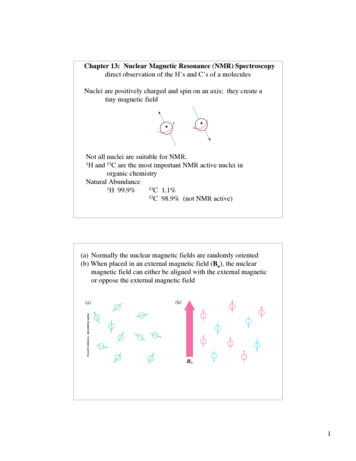
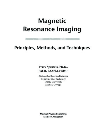
Table 1. Initial MRI protocols used for preoperative and postoperative imaging at our centerMRI protocolParameter1.5-tesla MRI scanner (model)General Electric (Horizon)Siemens (Vision)Philips (Intera)T2-weighted FSEField of viewMatrixSlice thicknessNumber of slicesInterleavedTR/TE/flip angleEcho train lengthBandwidthSignal averagesScan timeReported SAR260 mm384 ! 2562 mm24yes3,000 ms/87 ms/90 1015.6 kHz410:48varies by patient weight260 mm256 ! 2562 mm26yes2,500 ms/108 ms/90 9195 Hz/pixel49:08varies by patient weight260 mm512 ! 2682 mm21yes3,000 ms/90 ms/90 16183 Hz/pixel68:423.0 W/kg3-Dimensional GREField of viewMatrixSlice thicknessNumber of slicesTR/TE/flip angleBandwidthSignal averagesScan timeReported SAR260 mm256 ! 1921.5 mm11436 ms/8 ms/35 15.6 kHz0.7511:00varies by patient weightMPRAGE 260 mm256 ! 2561.5 mm12815 ms/4.4 ms/15 130 Hz/pixel18:10varies by patient weight260 mm256 ! 1921.5 mm12020 ms/2.9 ms/30 259 Hz/pixel18:460.6 W/kgIR FSEField of viewMatrixSlice thicknessNumber of slicesInterleavedTR/TE/flip angleInversion timeEcho train lengthBandwidthSignal averagesScan timeReported SARNA260 mm256 ! 2302 mm27yes3,000 ms/40 ms/90 200 ms9208 Hz/pixel311:53varies by patient weight260 mm512 ! 2562 mm28yes3,000 ms/40 ms/90 200 ms5120 Hz/pixel311:481.4 W/kgGRE Gradient echo; IR inversion recovery; TR repetition time; TE echo time; MPRAGE magnetization-prepared rapidgradient echo.dom sample of 13 MRI events is shown in table 3. A combination of body transmit/head receive and head transmit/receive (T/R) coils were used, with SAR ranging from0.1 to 3.0 W/kg. A representative postoperative scan usingour current imaging protocols is shown in figure 1. Thispatient had cervical and truncal dystonia as well as spasmodic dysphonia. The patient received simultaneous bilateral subthalamic nucleus and globus pallidus DBS implantations with 4 Medtronic 3387 leads and 2 Kinetrapulse generators placed in the same setting. Pre- andpostoperative imaging was obtained with a Philips Intera1.5T, running the Achieva release 1.5 software package94Stereotact Funct Neurosurg 2008;86:92–100and using a head T/R coil. The 3-dimensional T1-weighted sequence head SAR was 0.3 W/kg. The T2-weightedFSE sequence head SAR was 1.4 W/kg.DiscussionIn this study, we reviewed our experience with MRI ofover 700 DBS electrodes, using a variety of MRI scannersand protocols, over a 7-year period. DBS has become awidely accepted and adopted treatment modality for avariety of disorders [14–23]. Many advocate postoperaLarson /Richardson /Starr /Martin
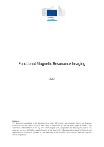
Table 2. Current MRI protocols with relatively lower SAR used for preoperative and postoperative imaging at our centerMRI protocolParameter1.5-tesla MRI scanner (model)General Electric (Signa)Siemens (Symphony)Philips (Achieva)T2-weighted FSEField of viewMatrixSlice thicknessNumber of slicesInterleavedTR/TE/flip angleEcho train lengthBandwidthSignal averagesScan timeReported SAR260 mm384 ! 2242 mm24yes2,500 ms/90 ms/90 1015.63 kHz48:101.67 W/kg(for a patient weight of 74.8 kg)260 mm256 ! 2562 mm26yes2,500 ms/108 ms/90 9195 Hz/pixel49:471.4 W/kg(for a patient weight of 74.8 kg)260 mm384 ! 2622 mm21yes3,000 ms/90 ms/90 16147 Hz/pixel68:420.5 W/kg3-Dimensional GREField of viewMatrixSlice thicknessNumber of slicesTR/TE/flip angleBandwidthSignal averagesScan timeReported SAR260 mm256 ! 1601.5 mm11433 ms/3 ms/35 15.63 kHz0.757:550.50 W/kg(for a patient weight of 74.8 kg)MPRAGE 260 mm256 ! 2561 mm1281910 ms/10 ms/15 130 Hz/pixel18:100.1 W/kg(for a patient weight of 74.8 kg)260 mm192 ! 1921.5 mm12020 ms/2.9 ms/35 259 Hz/pixel18:500.3 W/kgIR FSEField of viewMatrixSlice thicknessNumber of slicesInterleavedTR/TE/flip angleInversion timeEcho train lengthBandwidthSignal averagesScan timeReported SARNA260 mm256 ! 2302 mm27yes3,000 ms/48 ms/90 200 ms9208 Hz/pixel311:530.8 W/kg(for a patient weight of 74.8 kg)260 mm304 ! 2282 mm28yes3,000 ms/40 ms/90 200 ms5120 Hz/pixel311:540.8 W/kgGRE Gradient echo; IR inversion recovery; TR repetition time; TE echo time; MPRAGE magnetization-prepared rapidgradient echo. All protocols use head T/R coils. SAR for General Electric and Siemens platforms based on a patient weight of 74.8 kg.tive imaging with either computerized tomography (CT)or MRI to confirm lead location and to rule out complications such as hemorrhage. CT has the advantage of having no potential interactions with the metallic components of a DBS system, but offers no direct visualizationof the brain target due to poor tissue discrimination.Postoperative CT must be fused with preoperative MRIto provide any meaningful data regarding lead location,a technique that is time consuming and can introduce error to this process [24–26].Implanted stimulation devices such as deep brainstimulators, dorsal column stimulators and cardiac pacemakers are potentially problematic when interacting withRF energy in a magnetic field [27–30]. These devices typically consist of a long electrode that runs some distancethrough the body from the pulse generator to the end organ, often with random turns or loops along its length.The RF pulses and magnetic gradient fields used duringMRI produce currents that can be conducted and focusedby these devices, with resultant heating at the stimulatingMRI of Implanted DBS SystemsStereotact Funct Neurosurg 2008;86:92–10095
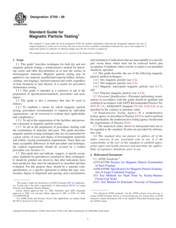
abFig. 1. T2-weighted images from a patient with bilateral globuspallidus interna and subthalamic nucleus electrodes. Imagesshown are directly from the MRI scanner and not reformatted tobe parallel to the intercommissural (AC-PC) plane; there is someasymmetry with the left side of the brain slightly higher than theright. The slice close to the AC-PC plane shows lateral leads relative to the globus pallidus (a), and the slice approximately 4 mmbelow the AC-PC plane shows medial leads relative to the subthalamic nucleus (b).surfaces of the electrode [31–34]. Heating of the stimulating surfaces in a cardiac pacemaker can cause local degradation of tissue contact that can reduce the effectiveness of the device, but this phenomenon is particularlyworrisome for devices placed in the brain, as excessivetissue heating is associated with permanent damage [35,36]. Temperature changes in the range of 5–7 C are associated with reversible lesions, while temperature elevations of 8 C or more are believed to cause irreversiblethermal injury [31, 37]. In addition, the pulse generatorsof stimulating devices can be switched on and off repeatedly during MRI, causing unwanted, target-specific sideeffects such as paresthesias in the case of DBS systemsimplanted in the thalamus or subthalamic nucleus.Manufacturer GuidelinesIn recent years, Medtronic has evolved specific guidelines for the use of MRI in patients with implanted DBScomponents. Those guidelines were most recently updated in November 2005 to include the following: (1) turnthe device off, with the amplitude set to zero and thestimulator mode in bipolar, (2) use only horizontal boreMRI systems operating at a static magnetic field of 1.5 T,(3) use only a T/R head coil that does not extend over thechest (IPG) area, (4) enter the correct patient weight intothe MRI console, (5) limit the gradient field to 20 T/s or96Stereotact Funct Neurosurg 2008;86:92–100less, and (6) use exam parameters that limit the displayedaverage head SAR (or applied SAR if known) to 0.1 W/kgor less for all RF pulse sequences. The last requirementrepresents a decrease in SAR from the prior recommendation of 0.4 W/kg [12, 38].The concept of SAR was developed to provide a measure for the rate of RF energy absorption by the body andwas first proposed in 1979 by the National Council onRadiation Protection and Measurements. At the time, theagency was primarily concerned with exposure to radiowaves, which is the frequency range in which MRI systems operate. The aim of measuring SAR in MRI systemsis to limit the rise in tissue temperatures due to RF energy deposition, and mirrors restrictions that are placedon other RF sources such as cell phones and radio towers.It can be difficult to measure, however, so MRI manufacturers typically use proprietary ‘predictive models’ to assure that the industry standards for allowable SAR arenot broken; they further employ variable safety marginsand frequently report their SAR values as ‘less than’ rather than providing a specific value. The net effect is thatSAR is a rather poor index for predicting the potential forlocalized heating near DBS leads, but it is the only measure currently available.From a practical standpoint, following a recommendation based on SAR is problematic for a variety of reasons. SAR is a calculated estimate, not a measured value,and therefore the SAR that is presented to the MRI technologist at the time of scanning is dependent on manyfactors. The method of SAR calculation itself is not standardized and varies from scanner to scanner. Two identical model scanners from the same manufacturer can differ in their method of SAR calculation if the softwareversion they are running is different. In some scanners,such as our GE and Siemens platforms, the SAR calculation is dependent on the MRI technologist entering thepatient’s body weight. This is often inaccurately recordedin the chart, underestimated by the patient and/or poorlyestimated by the technologist, as was the case with patient 13 in table 3 (weight entered 104 kg, actual weight132 kg). In some instances, the scanner will not proceedwith a particular sequence if the SAR exceeds a certainlevel set by the scanner software. Some technologists willintentionally enter an inaccurate body weight in such circumstances in order to allow scanning to proceed [Larson, pers. commun.].Reported Adverse EventsThe issue of safety in patients undergoing MRI withimplanted DBS systems came to the forefront severalLarson /Richardson /Starr /Martin
Table 3. Scan conditions and SAR for a sample of MRI eventsPatient YearNo.Implanted lead(s), IPG(s)ScannerCoils usedSequencesbody transmit,birdcage head receivebody transmit,birdcage head receivebody transmit,birdcage head receive3D GRE8:50IR TSE11:543D GRE8:50IR TSE11:543D GRE8:508:42T2-weighted axialdiffusion1:06FLAIR3:533D GRE8:503D GRE18:50T2-weighted axial8:428:42T2-weighted axial13:10T1-weighted GRE3D GRE8:50T2-weighted axial8:42T2-weighted axial18:423D GRE8:508:42T2-weighted axial3:10T1-weighted GRE3D GRE8:50T2-weighted axial8:42T1-weighted sagittal 2:303D GRE8:508:42T2-weighted axialT1-weighted sagittal 2:303D GRE8:508:42T2-weighted axial3D GRE8:508:42T2-weighted axial3D GRE8:508:42T2-weighted axialT2-weighted axial18:423D GRE8:508:42T2-weighted axial8:10T1-weightedMPRAGET2-weighted axial9:4712001Medtronic 3387, SoletraPhilips22002Medtronic 3387, Itrel IIPhilips32002Medtronic 3387 !2, Soletra !2Philips42003Medtronic 3387 !2, Soletra !2Philipsbody transmit,birdcage head receive52004Medtronic 3387 !2, Soletra !2Philipsbody transmit,birdcage head receive62004Medtronic 3387 !4, Soletra !4Philips72004Medtronic 3387, SoletraPhilipsbody transmit,SENSE head receivebody transmit,SENSE head receive82004Medtronic 3387 !2, Soletra !2Philipsbody transmit,birdcage head receive92005Medtronic 3387 !2, KinetraPhilipsbody transmit,SENSE head receive102005Medtronic 3387 !2, Soletra !2Philips112005Medtronic 3387 !2, KinetraPhilipsbody transmit,birdcage head receivebody transmit,birdcage head receive122006Medtronic 3387 !2, KinetraPhilipshead T/R132006ANS Quattrode !2, Libra !2Siemenshead .63.00.63.03.00.31.40.121.52Philips scanner (patients 1–12) predicts SAR independent of patient weight, so SAR for a given sequence and coil arrangementwill be the same from patient to patient. Siemens scanner (patient 13) calculates SAR based on patient weight as entered by the MRItechnologist. GRE Gradient echo; IR inversion recovery; TSE turbo spin echo; FLAIR fluid-attenuated inversion recovery;MPRAGE magnetization-prepared rapid gradient echo.1Sequence repeated due to motion.2 Siemens scanner, patient weight entered by the technologist 104 kg, actual patient weight 132 kg.years ago after two reports of serious injury during MRI.The first case involved a patient with bilateral DBS leadsand Soletra pulse generators, one in the typical subclavicular location on the right and the other in the abdominal wall with a longer lead extension on the left. The patient had a lumbar MRI scan using a 1.0-tesla scanner anda whole-body RF coil. The patient emerged with alteredmental status, and subsequent CT and MRI of the brainshowed a 2- to 3-cm presumed thermocoagulation lesionaround the left brain lead with a small amount of associated hemorrhage. There was no injury associated with theright-sided lead, which was connected to the IPG in theMRI of Implanted DBS SystemsStereotact Funct Neurosurg 2008;86:92–10097
chest. The patient was left with permanent disability [10,39]. The second case involved a patient with bilaterallyimplanted DBS leads that were externalized. The patientunderwent cranial MRI using a head T/R coil, also in a1.0-tesla scanner, with both leads fixed outside the coil ina straight manner. The patient emerged with dystonicand ballistic movements in the left leg, and although CTimaging was inconclusive and the patient did not consentto further MRI, an acute thermal injury of the right subthalamic nucleus was presumed. The dystonic and ballistic left leg movements resolved by 17 months after theincident [11].Both of these cases represent a unique set of circumstances that likely contributed to or were the sole cause ofthese adverse events. Both incidents occurred in 1.0-teslascanners which are uncommon, use a different RF wavelength and whose field interactions with DBS systems arenot well characterized, although there is a recent reportof 1.0-tesla MRI being used for postoperative imaging inDBS patients [40]. In our series, all patients were scannedon 1.5-tesla platforms. The first case involved the use ofa whole-body RF coil for spine imaging and a patient withan abdominally placed IPG. Earlier in our series, beforethe potential dangers of using body coils were described,we scanned many patients using body transmit/head receive coils without adverse events. Four patients in ourseries were scanned with abdominally placed IPGs, although we cannot retrospectively confirm what transmitcoils were used in those cases. In addition, at least 19spine MRI scans (cervical and lumbar) were performedfor spine issues in our implanted DBS patients, also without incident. The second case of patient injury involvedbilaterally externalized DBS leads; in our series, no patients were scanned with externalized leads.It is unclear if having the pulse generator amplitude setto zero and having the stimulating mode set in a bipolarconfiguration has any role in the generation of heating orother adverse events. While it is our current practice toturn the IPG off and set the amplitude to zero, we havenot routinely placed the stimulating mode to bipolar prior to performing MRI. We have occasionally scanned patients with the IPG turned off but the amplitude still setto therapeutic levels of stimulation; some of these patientshave reported transient paresthesias that would be consistent with the IPG being switched on and off duringimaging. No long-term adverse effects have occurred inthese patients, and no damage or alteration in IPG function has been observed. All patients with implanted IPGsshould undergo interrogation of their devices followingMRI to confirm proper stimulation parameters.98Stereotact Funct Neurosurg 2008;86:92–100Phantom Model ImagingExperimental testing has been performed by variousgroups to examine the heating of DBS components in theMRI environment. The results are quite variable and dependent on numerous factors, such as the scanner configuration (including field strength and RF wavelength),placement of the DBS system with respect to the bore ofthe MRI scanner and/or coils, coil selection, method andlocation of temperature measurements, and pulse sequences used [13, 34, 41, 42]. Finelli et al. [31] performedphantom studies of DBS electrodes examining the potential for heating at the electrode tip with a variety of clinically used pulse sequences at 1.5 T. They found a linearrelationship between SAR and electrode heating, althoughtemperature elevations with local (head) SAR !2.4 W/kgwere less than 2 C, i.e. in the clinically tolerable range[31]. This group also demonstrated that the method oftesting is important and can have a profound impact onthe heating seen at the electrode tip. The type of RF coilused, for example, had a profound impact on electrodeheating. ‘Worst case’ scenarios using body T/R coils andpulse sequences with SAR up to 3.9 W/kg lasting up to 15min produced temperature changes at the electrode tip ofup to 23.5 C. By contrast, switching to the head only T/Rcoil produced a maximum temperature change of 7.1 C[27]. A more recent study examined the use of a head onlyT/R coil in two different generation scanners from thesame manufacturer. Temperature changes were measuredand normalized to the head SAR values displayed by thescanner console. A statistically significant 3.5- to 5.5-folddifference was seen in the slope of normalized temperature change between the two scanners, indicating thatconsole-reported SAR itself is not a reliable index of heating for DBS leads [13]. Others have stated that using SARas a safety recommendation in the setting of an implanteddevice is misleading and potentially dangerous [43].Clinical ImagingIt is unfortunate that the imaging sequences that provide the best visualization of the target nuclei, T2-weighted FSE and inversion recovery FSE, typically have inherently higher SAR values. Reducing the SAR of these sequences to 0.1 W/kg or less may degrade image qualitysuch that the scan is no longer anatomically informativeor create a scan that is prohibitively long. Furthermore,there are presently no reliable data reflecting the relativerisk of MRI at specific SAR levels against which the clinical benefits of the procedure may be weighed. Somescanners do provide the option of using a ‘low SAR’ T2weighted protocol, however, these T2-weighted sequencesLarson /Richardson /Starr /Martin
do not reduce the SAR to the 0.1 W/kg recommendation.Custom sequences can be developed to provide the lowestSAR possible, but in most cases this requires the expertiseof a dedicated MRI physicist with access to and controlover details of the RF pulses used in these acquisitions.Many centers unfortunately do not have access to suchresources; moreover, the differences in the way variousmanufacturers’ platforms work are significant enoughthat one person may not be able to customize sequencesfor multiple platforms.At our center, we have experimented with ultralowSAR T2-weighted sequences on our Philips scanner tominimize image degradation and achieve an SAR of 0.2W/kg. This is accomplished by reducing the number andamplitude of RF pulses and altering pulse shape. Wefound an effective strategy of reducing the number of RFrefocusing pulses by half, which would normally doublethe scan time. We compensated for this by performinghalf the number of signal averages. Signal-to-noise ratiocan be maintained by taking advantage of the wider RFpulse spacing to reduce the acquisition bandwidth byhalf. RF refocusing pulses that are substantially less than180 may also be employed to reduce SAR in FSE images.Likewise, reducing the peak amplitude of RF pulse reduces SAR but lengthens the pulse duration, which cancause timing problems in the pulse train. When this occurs, the shape of the pulse can be changed, typically sacrificing the integrity of the slice profile for shorter RFpulse durations but maintaining the flip angle. Despitethis ability to perform acceptable T2-weighted imagingwith ultralow SAR on our Philips scanner, we still use aT2-weighted sequence that has an SAR of 0.5 W/kg due toconcern regarding some of the compromises necessaryfor further SAR reduction.It is important to recognize that the series of patientsreported here were scanned under varying circumstanc-es that would be encountered at any center. A wide variety of scanning parameters were used in a nonprospective manner on multiple hardware and software environments over a long time period, with MRI technologists ofvarying skill levels. We are of the impression that scanning at an SAR of 0.1 W/kg results in zero risk of thermaldamage due to RF-induced heating under typical conditions. Unfortunately, it is not clear what the risks of imaging at an SAR of 0.4 W/kg or higher really are. We havecarefully modified our scanning methods over the yearsto remain compliant with most manufacturer guidelines,but have never scanned a patient with an SAR of less than0.1 W/kg in all
desired brain target and rule out surgical complications such as intracranial hemorrhage [1-9] . K nowledge of ap-propriate lead location is important in predicting patient outcome and facilitates DBS programming. The immedi-ate feedback that postoperative imaging provides is also critically important for quality assurance, as it allows