Transcription
RPR Technology White PaperH3C SR8800 RPR Technology White PaperKeywords: RPR, IP ring networkAbstract: Resilient Packet Ring (RPR) is an international standard for establishing IP ring networks, offeringa highly efficient and reliable metropolitan area network (MAN) networking technology. RPR hasnumerous advantages over earlier ring network technologies. This document describes itsimplementation, characteristics, and basic applications, as well as the unique implementation on theSR8800.Acronyms:AcronymFull spellingFRRFast ReRouteFSForce SwitchLSPLabel Switching PathMPLSMultiprotocol Label SwitchingMSManual SwitchOAMOperations, Administration, MaintenanceRPRResilient Packet RingTPTopology ProtectTCTopology ChecksumHangzhou H3C Technologies Co., Ltd.Page 1/16
RPR Technology White PaperTable of ContentsOverview ·· 3RPR Features ···················· 3Concepts ····················· 3Span ····················· 3Edge ····················· 3Wrapping ··············· �····················· 3Host ······················ 4Ringlet Selection Table ····················· 4Protocol Processing Mechanism ··············· 4Data Operations on RPR Stations ······ 4Efficient Bandwidth Usage ················· 6Automatic Topology Discovery ··········· 6Topology Protection and Self-healing ·· 6Fairness Algorithm ·· 8QoS Guarantee ······ 9Miscellaneous ······ 11RPR Data Frame Format ······················· 11RPR Application Scenarios ······················· 12Application in Small and Medium-Sized MANs and LANs ···· 13Application in Large and Medium-Sized IP MANs ··············· 14RPR Features on the SR8800 ····················· 15Powerful Service Switching Performance · 15Complete QoS Capabilities ···················· 15Abundant Ring Selection ·········· 15Ease of Configuration ·· 15High Reliability ············ 15Mate Port Smart Connection ·················· 16References ······················ 16Hangzhou H3C Technologies Co., Ltd.Page 2/16
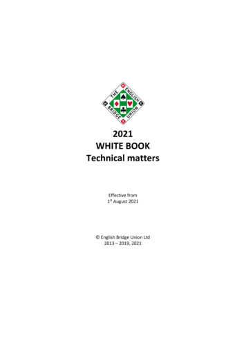
RPR Technology White PaperOverviewResilient packet ring (RPR) is a MAC layer technology standardized by the IEEE 802.17 workgroup. Itis independent of the physical layer and can run on SONET/SDH, Ethernet, and dense wavelengthdivision multiplexing (DWDM).Integrating the high reliability of SDH self-healing and Ethernet advantages such as low cost, largebandwidth, flexibility, and scalability, the RPR technology provides bandwidth management with dataoptimization capability and high-performance multi-service transmission on a ring topology.RPR FeaturesConceptsFigure 1 RPR ring topologyedgeS0spanS1S2linksS3S4Congestion domainS2S553S254inner ringletouter ringletSpanThe portion of a ring bounded by two adjacent stations. A span comprises a pair of unidirectional linkstransmitting in opposite directions.EdgeA span on which data frames are not allowed to pass is called an edge. An edge can result from fibercut, signal degradation, manual switch, or any other error or protection action.WrappingWrapping is a protection mechanism of RPR. When an edge occurs (a span or station fails), thisprotection mechanism redirects traffic to the original destination by sending it in the opposite directionaround the ring. The two ringlets thus form a closed single ring around the point of the failure. Aswrapping allows quick switchover without ringlet selection update, data frame loss is minimized, but atthe price of bandwidth.SteeringSteering is another protection mechanism of RPR. In steering mode, the RPR stations on the ringletupdate the ringlet selection upon detection of an edge. Based on the update result, the protectedtraffic is steered to the newly selected ringlet. The steering mechanism thus avoids the bandwidthHangzhou H3C Technologies Co., Ltd.Page 3/16
RPR Technology White Paperwaste with the wrapping mechanism, but as it requires topology reconvergence, it can cause frameloss and service interruption.HostFor the purpose of this document, the upper layer of the RPR MAC layer is referred to as the host.The host receives, processes, and transmits traffic destined for the local station.Ringlet Selection TableEach RPR station maintains a ringlet selection table, which stores information such as ringlets andhops to reach other stations on the RPR ring.When the ring is closed, two paths are available for reaching a destination, of which the shortest oneis selected by default.Protocol Processing MechanismRPR consists of two unidirectional counter-rotating ringlets identified as Ringlet 0 and Ringlet 1. Alllinks on the ring operate at the same data rate. The two ringlets of RPR can transmit data frames andcontrol frames at the same time.Each RPR station is identified by a 48-bit MAC address. The MAC address of an RPR station on theRPR ring must be unique. The two physical optical interfaces of an RPR station correspond to onelogical interface on the network layer.Data Operations on RPR StationsStations on an RPR ring handle data frames by performing the following operations: Insert: to place a frame received from outside of the RPR ring onto a ringlet. Transit: to pass a frame to the next station. As the frame is quickly forwarded at the RPR MAClayer, the throughput of the RPR station is improved. For a multicast/unicast data frame, the RPRstation also sends a copy to the upper layer. Copy: to deliver an inbound frame from the ring to the upper layer. The copying of a frame doesnot imply its removal from the ring. Strip, to remove a frame from a ringlet. A station strips a frame if the frame is destined for orsourced from the local station, or if the time to live (TTL) value of the frame expires.The source station inserts the unicast frame into the data stream on Ringlet 0 or Ringlet 1, the transitstations transit the frame, and the destination station copies and strips the frame.For a multicast or broadcast frame, the stations on the RPR ring copy and transit the frame. When theframe travels back to the source, the source station strips the frame from the ring.Figure 2, Figure 3, and Figure 4 show how unicast, multicast, and broadcast frames are transmittedon an RPR ringlet respectively.Hangzhou H3C Technologies Co., Ltd.Page 4/16
RPR Technology White PaperFigure 2 Unicast transmission on an RPR ringTransitInsert toringlet 0Copy fromringlet 0StripInsert toringlet 1StripTransitCopy fromringlet 1TransitStripFigure 3 Broadcast transmission on an RPR ringCopy fromringlet 0Insert toringlet 0Copy fromringlet 0StripCopy fromringlet 0Copy fromringlet 0StripFigure 4 Multicast transmission on an RPR ringCopy fromringlet 0Insert toringlet 0TransmitStripTransmitTransmitStripHangzhou H3C Technologies Co., Ltd.Copy fromringlet 0Page 5/16
RPR Technology White PaperEfficient Bandwidth UsageRPR allows efficient bandwidth usage on a ring network: Destination stripping: Traditional ring technologies such as SDH/SONET use source stripping,where a unicast frame is removed from the ring only after it returns to the source station, RPRadopts destination stripping where a unicast frame is removed from the ring as soon as itreaches the destination station. Spatial reuse: The adding of individual frames is not synchronized between ringlets. On an RPRring, the frame transmission event on any one link is independent of frame transmission eventson other links. With the RPR ring topology, this allows per-link bandwidth to be utilized beyondthat possible with other ring-based LAN technologies. By supporting concurrent per-ringlettransmissions, the bandwidth available to the stations on a ringlet exceeds the individual linkcapacity. On non-overlapping segments, concurrent transmissions of independent traffic areallowed. On overlapping segments, bandwidth allocated for traffic transmissions is assignedbased on a bandwidth fairness algorithm. Automatic bandwidth allocation: Different from the complex static bandwidth allocation with SDH,RPR supports bursty traffic, allowing fast service deployment. No redundant bandwidth: Unlike SDH, RPR can transmit frames on both ringlets without havingto reserve bandwidth for protection purpose. With RPR, the two ringlets back up each other toachieve self-healing. Support for broadcast and multicast: For a broadcast or multicast frame, only one copy travels onthe ring. This broadcast/multicast frame is copied and transited on each RPR station and strippedoff from the ring when it travels back to the source station. L2 rapid forwarding: As a station processes only frames destined for it, forwarding speed isimproved.Automatic Topology DiscoveryEach station on an RPR ring uses topology and protection (TP) frames to broadcast its topology andprotection status information. After receiving the information, other stations update their local topologydatabases. In this way, all stations on the ring eventually maintain a consistent topology database.When detecting a protection state change, a station first sends eight TP frames at (short) intervals of1 to 20 milliseconds (the default is 10 milliseconds). Then, it sends TP frames periodically at (long)intervals of 50 milliseconds to 10 seconds (the default is 100 milliseconds). This mechanism enablesall stations on the ring to sense protection and topology changes timely and reliably, ensuring timelyprotection switchover in addition to topology synchronization.The automatic topology discovery mechanism of RPR achieves “plug and play” for RPR stations,allowing the stations to obtain the ring topology information and be sensed by other stationsautomatically.Topology Protection and Self-healingRPR can provide protection against sudden failures, allowing services to recover within 50milliseconds. RPR provides two protection mechanisms: steering and wrapping.In steering mode, a station, upon detection of a fault on a ringlet, broadcasts the protection statechange with TP frames on the ring. This also triggers ringlet selection. When other stations receiveHangzhou H3C Technologies Co., Ltd.Page 6/16
RPR Technology White Paperthe TP frames, they transit to the corresponding protection state, recalculate the reachability of thestations on the ring, and update their ringlet selection tables to select the ringlet that retainsconnectivity to the destination stations.Unlike the steering mode, the wrapping mode does not involve ringlet selection update on the entirering. Instead, the stations at both sides of a point of failure transit to the wrapping mode upondetection of the failure while other stations transmit traffic along the original path. When the protectedtraffic arrives at the station on one side of the point of failure, it is directed to the opposing healthyringlet to reach the station on the other side of the point of failure. Then the protected traffic travelsalong the original ringlet to reach the destination.Compared with the steering mode, the wrapping mode provides quicker protection resulting in lessframe loss but requires more bandwidth.Figure 5 Path from Station A to Station B before a fault occursStation BPath beforeswitchoverStation AFigure 6 Path steering upon detection of a fault (A - B)Station BSteered pathStation AHangzhou H3C Technologies Co., Ltd.Page 7/16
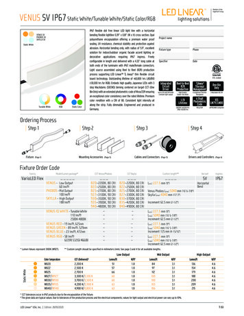
RPR Technology White PaperFigure 7 Path wrapping upon detection of a fault (A - B)Station AStation BWrapped pathTo benefit from both, the RPR implementation of the SR8800 adopts the wrap-then-steer mode. Inthis mode, RPR starts the wrapping mode once a link fails to ensure continuity of the ongoing serviceand reduce short-term frame loss, and switches to the steering mode after the topology converges toimprove long-term ringlet utilization efficiencies.Fairness AlgorithmResources on a ring network are shared among the stations. RPR provides a global fairnessalgorithm on the entire ring network to guarantee the fairness of the sharing and improve bandwidthusage efficiency. The fairness algorithm of RPR can regulate traffic dynamically to minimize thepossibility of congestion and to handle bursty large volume traffic effectively, thus ensuring normaloperation of the network.To achieve bandwidth allocation fairness, each RPR station monitors the use of its bandwidth andprovides an explicit backpressure mechanism between stations. With this mechanism, the stationnotifies a source station of the current available capability, having the source station regulate traffictransmission. Thus, bandwidth allocation fairness is achieved on the ring.The fairness algorithm of RPR involves the following three aspects: Determining the congestion threshold on a station Determining the broadcast rate to the upstream station Determining the traffic insertion rate on a stationWhen congestion occurs on a station, the station sends an advertisement on the ringlet opposite tothe data transmission direction to advertise a fair rate. Receiving the advertisement, the upstreamstation then decreases the frame insertion rate down to the advertised fair rate. If congestion alsooccurs on the current station, it does the same as its downstream station did.To guarantee high-priority services, bandwidth management regulates low-priority data frames, butnot high-priority data frames or control frames. The bandwidth management capability of RPR allowsfor bandwidth allocation efficiency and fairness, which cannot be provided by Ethernet or other ringnetwork technologies where bandwidth management is not available.The following figure illustrates how the fairness algorithm works on an RPR ring comprising stations A,B, C, D, E, and F. Suppose the bandwidth of each link is 10 Gbps and traffic travels Ringlet 0.Hangzhou H3C Technologies Co., Ltd.Page 8/16
RPR Technology White PaperFigure 8 Bandwidth fairness algorithmBASendolcontresmfra4 Gbps3.3 GbpsCSe4 Gbpsco nd3 Gbpsntr3.3 Gbps fram oles4 Gbps2 Gbps3 Gbps3.3 GbpsCongested10G RPRFDEThe following is what occurs on the RPR ring:1)Both stations C and B send 4 Gbps traffic to station D. They share bandwidth on span C–D andrepresent 8-Gbps bandwidth in total. As the link bandwidth is 10 Gbps, no congestion is present.2)Station A also sends 4 Gbps traffic to station D. As a result, the total traffic on span C–D reaches12 Gbps, exceeding the maximum link bandwidth (10 Gbps). Congestion thus occurs on span C–D.3)With the fairness algorithm, station C performs calculation immediately after detecting thecongestion to decrease the rate of putting traffic onto the ring to 2 Gbps. In the mean time, itsends control frames to station B reversely along the inner ringlet to transmit congestion andfairness algorithm information.4)Upon receiving the fairness control frames, station B immediately decreases its traffic rate andsends fairness control frames to station A. According to the fairness algorithm, both station C andstation B adjust traffic rate to 3 Gbps.5)After receiving the control frames, station A acts likewise.By repeating this process, stations A, B and C adjust their traffic rates to 3.3 Gbps, sharing bandwidthfairly.In this example, absolute fairness is maintained. RPR, however, allows exclusive bandwidth allocationand weighted bandwidth allocation. Thus, traffic rate can be different at each station depending on itsfairness weight.QoS GuaranteeWith the capability of 50 milliseconds self-healing, efficient bandwidth use, and advanced RPR-Faalgorithm, RPR can provide QoS guarantee for services, achieving high reliability, large throughput,low delay, and low loss rate.RPR services fall into three classes: class A, class B and class C, with decreasing priorities. Class A: Provides an allocated, guaranteed data rate, a low end-to-end delay, and low jitter tosupport time division multiplexing (TDM) services. It is subdivided into subclasses A0 and A1. Forthe A0 service, bandwidth is reserved on the entire ring and the unused reserved bandwidthHangzhou H3C Technologies Co., Ltd.Page 9/16
RPR Technology White Papercannot be used for lower priority services. For the subclass A1 and class B services, bandwidthis reclaimable and the unused bandwidth can be used for lower priority services. Class B: Provides an allocated, guaranteed data rate, and low delay and jitter to transmit data bythe priority order. Class B can be divided into two subclasses: committed information rate (CIR)and excess information rate (EIR), that is, B-CIR and B-EIR. Class C: Provides a best-effort service with no allocated or guaranteed data rate and no boundson delay or jitter for traditional IP traffic.RPR uses the Sc field to indicate the priority of an RPR frame.For traffic to be forwarded, the RPR MAC layer adopts either a single transit queue or dual transitqueues. On a single-queue station, all traffic is transmitted in a first in first out (FIFO) queueregardless of their priorities. On a dual-queue station, traffic is transmitted either in the primary transitqueue or in the secondary transit queue as follows: Class A traffic: transmitted in the primary transit queue. Class B traffic: transmitted in the secondary transit queue. The subclass B-CIR traffic hasprecedence over the class C traffic and is not regulated by the fairness algorithm. The subclassB-EIR traffic has the same priority as the class C traffic and is regulated by the fairness algorithm. Class C traffic: transmitted in the secondary transit queue.A CIR is allocated for the class B services. Traffic conforming to the CIR has precedence over thenonconforming traffic (B-EIR traffic).The RPR MAC layer controls the traffic transmission order, which differs with the queue model. On a dual-queue stationThe RPR MAC layer assigns traffic sent by the host to the host queue and traffic to be forwarded forother stations to the transit queues. The RPR MAC layer dequeues frames from the transit queues inthe following order:1)Frames in the primary transit queue.2)Class A frames so long as the secondary transit queue is not full. In case the length of thesecondary transit queue exceeds a specified threshold, the frames in the queue are sent.3)B-CIR frames.4)B-EIR and Class C frames, if the fairness algorithm is obeyed.5)Frames in the secondary transit queue, if no higher priority frames are waiting for transmission. On a single-queue stationFrames in the transit queue are transmitted first, regardless of their priorities. The class C andsubclass B-EIR frames are regulated by the fairness algorithm.RPR supports bandwidth reservation, providing perfect QoS guarantee for reserved bandwidth. Thus,the traditional voice traffic can be transmitted.Because the fairness algorithm of RPR does not regulate the high-priority traffic, all high-priority trafficwill always be sent prior to low-priority traffic. To prevent excessive high-priority traffic from affectinglow-priority traffic, you are recommended to set a threshold for high-priority traffic.RPR provides multiple static traffic shaping methods such as rate limiting (using a rate limiter) forhigh- and low-priority data frames. For low-priority data frames, RPR also provides dynamic trafficshaping.Hangzhou H3C Technologies Co., Ltd.Page 10/16
RPR Technology White PaperThe QoS guarantee measures of RPR ensure that an excellent QoS guarantee can be provided onan RPR ring even if the hosts do not provide QoS guarantee.MiscellaneousAs a physical layer-independent MAC layer protocol, RPR provides physical layer interfaces tosupport Ethernet, DWDM and SONET/SDH.RPR allows great bandwidth scalability. For example, your can scale RPR ring bandwidth from 155Mbps to 10 Gbps, and even to 40 Gbps.2A very important feature of RPR is that it avoids the N issue successfully to achieve full connectivityat the MAC layer for N stations with only N links. Compared with SDH, POS and Ethernet, RPR haslower link cost.RPR is an optimized Ethernet technology. It supports all Ethernet protocols and services.RPR supports equipment interoperability at the ring level. For example, you can connect ATM devices,routers, and TDM devices to the same RPR ring. These networks share the physical links and totalbandwidth of the ring while being transparent to each other.RPR provides complete MIB features, which allow RPR to provide an extraordinary operations andmaintenance platform, achieving operability and manageability.RPR Data Frame FormatFigure 9 RPR extended frame formatTTL (1 octet)Basic control (1 octet)MAC BMAC ATTL base number (1 octet)Extended control (1 octet)HEX (2 octets)MAC DMAC CProtocol type (2 octets)Data (N octets)FCS (4 octets)Hangzhou H3C Technologies Co., Ltd.Page 11/16
RPR Technology White PaperFigure 10 RPR basic frame formatTTL (1 octet)Basic control (1 octet)MAC BMAC ATTL base number (1 octet)Extended control (1 octet)HEX (2 octets)Protocol type (2 octets)Data (N octets)FCS (4 octets)There are two types of RPR data frames: basic data frames and extended data frames, as shown inthe figures above.Basic data frames are forwarded at Layer 3 while extended data frames are forwarded at Layer 2.Judging by the frame structures, basic data frames use less bandwidth. For this reason, unicast andbroadcast frames on the SR8800 are all forwarded as basic data frames.RPR Application ScenariosThis section presents various RPR application scenarios. Interconnected RPR stations form RPRrings, which are similar to SDH rings. RPR rings may intersect or touch. Devices connected to RPRstations can insert/copy traffic onto/from RPR rings through related cards (other than the oneconnected to the RPR ring) of the RPR stations.RPR supports various routing protocols. Protection switch due to fiber cut for example does not resultin route reconvergence or MPLS LSP re-establishment. This is because on an RPR ring, there aretwo paths to each destination station. When one fails, traffic can travel over the other to reach thedestination. The protection switchover takes less than 50 milliseconds, far less than the hello intervalof routing protocol neighbors. Moreover, the DOWN event of a physical port will not be reported to theupper layers, unless both physical ports of an RPR station are down. Therefore, using RPR rings toconnect distribution and access services can provide high reliability and stability, whereas with STP orother ring network technologies, path switchover can result in update of service protocols involvingrouting, MPLS LSP, ARP, MAC, and so on. MPLS over RPR rings delivers unique advantages,providing sub-50 millisecond convergence for LSP services without FRR or a backup LSP.Hangzhou H3C Technologies Co., Ltd.Page 12/16
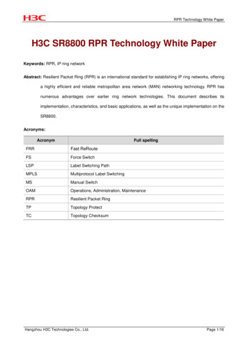
RPR Technology White PaperApplication in Small and Medium-Sized MANs and LANsFigure 11 RPR solution for small and medium-sized MANsIP backbonenetworkSR88SR88MAN core/distributionlayerMAN access layerRPR peed leasedline accessGE/FEGE/FEVPN accessFor a small or medium-sized city, an RPR ring can be built in the MAN. One or two of the stations canbe used as the core and egress uplinked to the backbone network. Other stations are deployed atimportant offices in the city to provide the following services: The access/distribution of Ethernet traffic in those areasThe access of various high- and low-rate leased line users: Various interfaces such as E1, E3,POS, and ATM can be provided on these stations, allowing them to serve as leased line accessrouters. The access of various VPN users: MPLS links can be established on the RPR ring, allowingrouters to serve as MPLS VPN PE devices to access various VPN users.RPR can operate at the core layer of local area networks (LANs) with geographically-dispersedagencies or branches, such as government networks, enterprise networks, and campus networks,connect offices, data centers, and the Internet, and logically optimize the existing FDDI ring networks,reserving the features as being a self-healing ring. Such application is shown in the figure below.Hangzhou H3C Technologies Co., Ltd.Page 13/16
RPR Technology White PaperFigure 12 RPR solution for LANsInternetCenterRPR ringBranchBranchBranchSubsidiary bodySubsidiary companyApplication in Large and Medium-Sized IP MANsFigure 13 RPR solution for large and medium-sized IP MANsIP backbonenetworkPPSR88SR88YMAN distributionlayerMAN core layerSR88PE2.5G RPRSR88SR882.5G RPREthernetSR88access/distributionHigh-speed leasedline accessVPN access10G RPRSR88PESR88MAN access layerE1/E3GE/FEGE/FEA large or medium-sized IP MAN contains a large number of core and distribution nodes. Hence, itusually adopts the typical three-layer architecture, namely, the core layer, distribution layer, andaccess layer. In such case, multiple RPR rings are often used for networking. On the core layer, aHangzhou H3C Technologies Co., Ltd.Page 14/16
RPR Technology White Papercore 10G RPR ring is built, and on the distribution layer, multiple 2.5G edge RPR rings are built. Thecore ring and edge rings can intersect or touch. When two rings intersect, they have two connectionpoints and thus provide higher reliability. Therefore, you are recommended to deploy intersected ringswherever possible.RPR Features on the SR8800Powerful Service Switching PerformanceAccording to the RPR protocol, fault detection should be done within 10 milliseconds and serviceswitching within 50 milliseconds. The RPR implementation on the SR8800 can complete serviceswitching as fast as within 20 milliseconds, fully satisfying the carrier-class requirement andemploying the strength of RPR.Complete QoS CapabilitiesThe RPR implementation on the SR8800 provides complete QoS capabilities for RPR traffic. Itsupports the access control list (ACL), rate limiting, traffic shaping, queuing, and almost all QoSfeatures available on Ethernet. It supports mappings from 802.1p, MPLS and IP priorities to RPRpriorities. Depending on customer needs, it supports services of Class A, B and C, providingbandwidth guarantee and other service differentiation capabilities. In addition, the RPRimplementation on the SR8800 uses a fairness algorithm to ensure fair access of stations to ringbandwidth, allowing for bandwidth usage efficiency, congestion avoidance, and congestion alarming.Abundant Ring Selection MechanismsThe RPR implementation on the SR8800 supports multiple ring selection modes.By default, dynamic ringlet selection (shortest path selection) is adopted on an RPR ring. Dynamicringlet selection results in a ringlet selection table that contains the shortest paths to other RPRstations on the ring upon topology convergence. This ringlet selection table does not change whenthe topology is stable.In addition, you can configure static ringlet selection entries, which have higher priority over dynamicentries.Ease of ConfigurationOn the SR8800 working as an RPR station, RPR provides a logical RPR interface for you to makerelated configuration as if on a common Ethernet port. The two RPR physical ports bound with thelogical RPR interface are transparent to the upper layers. All services are configured on the logicalRPR interface rather than on the two physical ports respectively.High ReliabilityAn RPR station is identical to an RPR logical interface bound with two physical ports. The twophysical ports are used to transmit data to or receive data from the ring and the logical interface isprovided for you to make configuration. The SR8800 supports distributed RPR, where the twoHangzhou H3C Technologies Co., Ltd.Page 15/16
RPR Technology White Paperphysical ports are located on different interface cards. Comparatively, centralized RPR means that thetwo physical ports are located
RPR Technology White Paper Hangzhou H3C Technologies Co., Ltd. Page 1/16 H3C SR8800 RPR Technology White Paper . Keywords: RPR, IP ring network. . Integrating the high reliability of SDH self-healing and Ethernet advantages such as low cost, large bandwidth, flexibility, and scalability, the RPR technology provides bandwidth management with .