Transcription
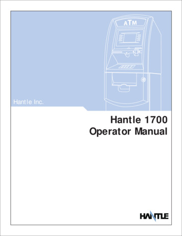
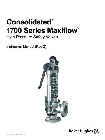
Consolidated1700 Series Maxiflow High Pressure Safety ValvesInstruction Manual (Rev.G)Baker Hughes Data Classification: Public
THESE INSTRUCTIONS PROVIDE THE CUSTOMER/OPERATOR WITH IMPORTANT PROJECTSPECIFIC REFERENCE INFORMATION IN ADDITION TO THE CUSTOMER/OPERATOR’SNORMAL OPERATION AND MAINTENANCE PROCEDURES. SINCE OPERATION ANDMAINTENANCE PHILOSOPHIES VARY, BAKER HUGHES (AND ITS SUBSIDIARIES ANDAFFILIATES) DOES NOT ATTEMPT TO DICTATE SPECIFIC PROCEDURES, BUT TO PROVIDEBASIC LIMITATIONS AND REQUIREMENTS CREATED BY THE TYPE OF EQUIPMENTPROVIDED.THESE INSTRUCTIONS ASSUME THAT OPERATORS ALREADY HAVE A GENERALUNDERSTANDING OF THE REQUIREMENTS FOR SAFE OPERATION OF MECHANICAL ANDELECTRICAL EQUIPMENT IN POTENTIALLY HAZARDOUS ENVIRONMENTS. THEREFORE,THESE INSTRUCTIONS SHOULD BE INTERPRETED AND APPLIED IN CONJUNCTION WITHTHE SAFETY RULES AND REGULATIONS APPLICABLE AT THE SITE AND THE PARTICULARREQUIREMENTS FOR OPERATION OF OTHER EQUIPMENT AT THE SITE.THESE INSTRUCTIONS DO NOT PURPORT TO COVER ALL DETAILS OR VARIATIONS INEQUIPMENT NOR TO PROVIDE FOR EVERY POSSIBLE CONTINGENCY TO BE MET INCONNECTION WITH INSTALLATION, OPERATION OR MAINTENANCE. SHOULD FURTHERINFORMATION BE DESIRED OR SHOULD PARTICULAR PROBLEMS ARISE WHICH ARE NOTCOVERED SUFFICIENTLY FOR THE CUSTOMER/OPERATOR'S PURPOSES THE MATTERSHOULD BE REFERRED TO BAKER HUGHES.THE RIGHTS, OBLIGATIONS AND LIABILITIES OF BAKER HUGHES AND THE CUSTOMER/OPERATOR ARE STRICTLY LIMITED TO THOSE EXPRESSLY PROVIDED IN THE CONTRACTRELATING TO THE SUPPLY OF THE EQUIPMENT. NO ADDITIONAL REPRESENTATIONS ORWARRANTIES BY BAKER HUGHES REGARDING THE EQUIPMENT OR ITS USE ARE GIVENOR IMPLIED BY THE ISSUE OF THESE INSTRUCTIONS.THESE INSTRUCTIONS ARE FURNISHED TO THE CUSTOMER/OPERATOR SOLELY TOASSIST IN THE INSTALLATION, TESTING, OPERATION, AND/OR MAINTENANCE OF THEEQUIPMENT DESCRIBED. THIS DOCUMENT SHALL NOT BE REPRODUCED IN WHOLE OR INPART WITHOUT THE WRITTEN APPROVAL OF BAKER HUGHES.2 Baker HughesCopyright 2020 Baker Hughes Company. All rights reserved.
Conversion TableUSCS to Metric ConversionUSCS UnitConversion FactorMetric rpsig0.06894757bargft lb1.3558181Nm F5/9 ( F-32) CNote: Multiply the USCS value by the conversion factor to get the metric value.NOTICE!For valve configurations not listed in thismanual, please contact your local GreenTag Center for assistance.Copyright 2020 Baker Hughes Company. All rights reserved.Consolidated 1700 Series Maxiflow Safety Valves Instruction Manual 3
Table of ContentsI.Product Safety Sign and Label System. . . . . . . . . . . . . . . . . . . . . . . . . . . . . . . . . . 6II.Safety Alerts . . . . . . . . . . . . . . . . . . . . . . . . . . . . . . . . . . . . . . . . . . . . . . . . . . . . . . . 7III.Safety Notice. . . . . . . . . . . . . . . . . . . . . . . . . . . . . . . . . . . . . . . . . . . . . . . . . . . . . . . 8IV.Warranty Information . . . . . . . . . . . . . . . . . . . . . . . . . . . . . . . . . . . . . . . . . . . . . . . . 9V.Valve Terminology. . . . . . . . . . . . . . . . . . . . . . . . . . . . . . . . . . . . . . . . . . . . . . . . . . 10VI.Handling and Storage. . . . . . . . . . . . . . . . . . . . . . . . . . . . . . . . . . . . . . . . . . . . . . . . 11VII.Design Features and Nomenclature . . . . . . . . . . . . . . . . . . . . . . . . . . . . . . . . . . . . 11VIII. Introduction. . . . . . . . . . . . . . . . . . . . . . . . . . . . . . . . . . . . . . . . . . . . . . . . . . . . . . . 13IX.Consolidated 1700 Series Safety Valve. . . . . . . . . . . . . . . . . . . . . . . . . . . . . . . . . 14A. Maxiflow Safety Valve – Flanged Inlet . . . . . . . . . . . . . . . . . . . . . . . . . . . . . . . . . . . . . . . . . . . . . 14B. Maxiflow Safety Valve – Welded Inlet . . . . . . . . . . . . . . . . . . . . . . . . . . . . . . . . . . . . . . . . . . . . . 15C. Valve Options. . . . . . . . . . . . . . . . . . . . . . . . . . . . . . . . . . . . . . . . . . . . . . . . . . . . . . . . . . . . . . . . . . 16X.Operating Principles. . . . . . . . . . . . . . . . . . . . . . . . . . . . . . . . . . . . . . . . . . . . . . . . . 17XI.Recommended Installation Practices. . . . . . . . . . . . . . . . . . . . . . . . . . . . . . . . . . 18A.B.C.D.XII.General Requirements. . . . . . . . . . . . . . . . . . . . . . . . . . . . . . . . . . . . . . . . . . . . . . . . . . . . . . . . . . . 18Outdoor Safety Valve Installation. . . . . . . . . . . . . . . . . . . . . . . . . . . . . . . . . . . . . . . . . . . . . . . . . . . 21Indoor Safety Valve Installation. . . . . . . . . . . . . . . . . . . . . . . . . . . . . . . . . . . . . . . . . . . . . . . . . . . . 22Coverplate Vent Piping. . . . . . . . . . . . . . . . . . . . . . . . . . . . . . . . . . . . . . . . . . . . . . . . . . . . . . . . . . . 22Disassembly of Consolidated 1700 Series Safety Valve. . . . . . . . . . . . . . . . . . . 23A. General Information. . . . . . . . . . . . . . . . . . . . . . . . . . . . . . . . . . . . . . . . . . . . . . . . . . . . . . . . . . . . . 23B. Specific Steps . . . . . . . . . . . . . . . . . . . . . . . . . . . . . . . . . . . . . . . . . . . . . . . . . . . . . . . . . . . . . . . . . 23XIII. Maintenance Instructions. . . . . . . . . . . . . . . . . . . . . . . . . . . . . . . . . . . . . . . . . . . . 26A. General . . . . . . . . . . . . . . . . . . . . . . . . . . . . . . . . . . . . . . . . . . . . . . . . . . . . . . . . . . . . . . . . . . . . . .B. Lapping Procedure. . . . . . . . . . . . . . . . . . . . . . . . . . . . . . . . . . . . . . . . . . . . . . . . . . . . . . . . . . . . . .1.General Information. . . . . . . . . . . . . . . . . . . . . . . . . . . . . . . . . . . . . . . . . . . . . . . . . . . . . . . . .2. To Lap the Bushing Seat . . . . . . . . . . . . . . . . . . . . . . . . . . . . . . . . . . . . . . . . . . . . . . . . . . . . .3. To Lap Disc Seat . . . . . . . . . . . . . . . . . . . . . . . . . . . . . . . . . . . . . . . . . . . . . . . . . . . . . . . . . . .C. Reseating Machine Information. . . . . . . . . . . . . . . . . . . . . . . . . . . . . . . . . . . . . . . . . . . . . . . . . . . .D. Spindle Runout. . . . . . . . . . . . . . . . . . . . . . . . . . . . . . . . . . . . . . . . . . . . . . . . . . . . . . . . . . . . . . . . .E. Disc Replacement and Disc-Spindle Bearing Requirements . . . . . . . . . . . . . . . . . . . . . . . . . . . . .F. Grinding the Compression Screw . . . . . . . . . . . . . . . . . . . . . . . . . . . . . . . . . . . . . . . . . . . . . . . . . .G. Thrust Bearing Surfaces . . . . . . . . . . . . . . . . . . . . . . . . . . . . . . . . . . . . . . . . . . . . . . . . . . . . . . . . .H. Grinding the Lower Spring Washer. . . . . . . . . . . . . . . . . . . . . . . . . . . . . . . . . . . . . . . . . . . . . . . . .2626262627283030323232XIV. Inspection and Part Replacement. . . . . . . . . . . . . . . . . . . . . . . . . . . . . . . . . . . . . 33A. General Information. . . . . . . . . . . . . . . . . . . . . . . . . . . . . . . . . . . . . . . . . . . . . . . . . . . . . . . . . . . . . 33B. Specific Steps . . . . . . . . . . . . . . . . . . . . . . . . . . . . . . . . . . . . . . . . . . . . . . . . . . . . . . . . . . . . . . . . . 334 Baker HughesCopyright 2020 Baker Hughes Company. All rights reserved.
Table of Contents1.2.3.4.5.6.XV.Disc Holder. . . . . . . . . . . . . . . . . . . . . . . . . . . . . . . . . . . . . . . . . . . . . . . . . . . . . . . . . . . . . . . .Guide . . . . . . . . . . . . . . . . . . . . . . . . . . . . . . . . . . . . . . . . . . . . . . . . . . . . . . . . . . . . . . . . . . . .Clearance. . . . . . . . . . . . . . . . . . . . . . . . . . . . . . . . . . . . . . . . . . . . . . . . . . . . . . . . . . . . . . . . .Disc. . . . . . . . . . . . . . . . . . . . . . . . . . . . . . . . . . . . . . . . . . . . . . . . . . . . . . . . . . . . . . . . . . . . . .Overlap Collar. . . . . . . . . . . . . . . . . . . . . . . . . . . . . . . . . . . . . . . . . . . . . . . . . . . . . . . . . . . . . .Coverplate . . . . . . . . . . . . . . . . . . . . . . . . . . . . . . . . . . . . . . . . . . . . . . . . . . . . . . . . . . . . . . . .333333333434Re-Assembly of Consolidated 1700 Series Safety Valve. . . . . . . . . . . . . . . . . . . 34A. General Information. . . . . . . . . . . . . . . . . . . . . . . . . . . . . . . . . . . . . . . . . . . . . . . . . . . . . . . . . . . . . 34B. Specific Steps . . . . . . . . . . . . . . . . . . . . . . . . . . . . . . . . . . . . . . . . . . . . . . . . . . . . . . . . . . . . . . . . . 34XVI. Setting and Testing . . . . . . . . . . . . . . . . . . . . . . . . . . . . . . . . . . . . . . . . . . . . . . . . 41A. Field Testing. . . . . . . . . . . . . . . . . . . . . . . . . . . . . . . . . . . . . . . . . . . . . . . . . . . . . . . . . . . . . . . . . . . 41A.1 General Information. . . . . . . . . . . . . . . . . . . . . . . . . . . . . . . . . . . . . . . . . . . . . . . . . . . . . . . . . 41A.2 Popping Point Adjustment . . . . . . . . . . . . . . . . . . . . . . . . . . . . . . . . . . . . . . . . . . . . . . . . . . . . 41A.3 Ring Adjustments, Blowdown and Overlap Collar Adjustments. . . . . . . . . . . . . . . . . . . . . . . . 42A.4 Restricted Lift Valves. . . . . . . . . . . . . . . . . . . . . . . . . . . . . . . . . . . . . . . . . . . . . . . . . . . . . . . . 45A.5 Consolidated Hydroset/Electronic Valve Tester (EVT). . . . . . . . . . . . . . . . . . . . . . . . . . . . . . . 45A.6 Sealing Valves After Test. . . . . . . . . . . . . . . . . . . . . . . . . . . . . . . . . . . . . . . . . . . . . . . . . . . . . 45B. Hydrostatic Testing and Gagging. . . . . . . . . . . . . . . . . . . . . . . . . . . . . . . . . . . . . . . . . . . . . . . . . . . 46XVII. Troubleshooting. . . . . . . . . . . . . . . . . . . . . . . . . . . . . . . . . . . . . . . . . . . . . . . . . . . . 47XVIII. 1700 Series Safety Valve Options . . . . . . . . . . . . . . . . . . . . . . . . . . . . . . . . . . . . . 48A. Hydrostatic Test Plug. . . . . . . . . . . . . . . . . . . . . . . . . . . . . . . . . . . . . . . . . . . . . . . . . . . . . . . . . . . . 48B. Hydroplug. . . . . . . . . . . . . . . . . . . . . . . . . . . . . . . . . . . . . . . . . . . . . . . . . . . . . . . . . . . . . . . . . . . . . 49XIX. Maintenance Tools and Supplies. . . . . . . . . . . . . . . . . . . . . . . . . . . . . . . . . . . . . . 50A. Lapping Tools. . . . . . . . . . . . . . . . . . . . . . . . . . . . . . . . . . . . . . . . . . . . . . . . . . . . . . . . . . . . . . . . . . 50A1. Ring Lap. . . . . . . . . . . . . . . . . . . . . . . . . . . . . . . . . . . . . . . . . . . . . . . . . . . . . . . . . . . . . . . . . . 50A2. Lapping Plate. . . . . . . . . . . . . . . . . . . . . . . . . . . . . . . . . . . . . . . . . . . . . . . . . . . . . . . . . . . . . . 50A3. Lapping Compound . . . . . . . . . . . . . . . . . . . . . . . . . . . . . . . . . . . . . . . . . . . . . . . . . . . . . . . . . 50B. Gags. . . . . . . . . . . . . . . . . . . . . . . . . . . . . . . . . . . . . . . . . . . . . . . . . . . . . . . . . . . . . . . . . . . . . . . . . 50C. Lubricant . . . . . . . . . . . . . . . . . . . . . . . . . . . . . . . . . . . . . . . . . . . . . . . . . . . . . . . . . . . . . . . . . . . . . 50D. Wrench Sizes. . . . . . . . . . . . . . . . . . . . . . . . . . . . . . . . . . . . . . . . . . . . . . . . . . . . . . . . . . . . . . . . . . 51XX.Replacement Parts Planning . . . . . . . . . . . . . . . . . . . . . . . . . . . . . . . . . . . . . . . . . 52XXI. Genuine Consolidated Parts . . . . . . . . . . . . . . . . . . . . . . . . . . . . . . . . . . . . . . . . . 53XXII. Recommended Spare Parts. . . . . . . . . . . . . . . . . . . . . . . . . . . . . . . . . . . . . . . . . . 53XXIII. Manufacturer’s Field Service & Repair Program . . . . . . . . . . . . . . . . . . . . . . . . . 55A. Field Service . . . . . . . . . . . . . . . . . . . . . . . . . . . . . . . . . . . . . . . . . . . . . . . . . . . . . . . . . . . . . . . . . . 54B. Repair Facilities. . . . . . . . . . . . . . . . . . . . . . . . . . . . . . . . . . . . . . . . . . . . . . . . . . . . . . . . . . . . . . . . 55C. Maintenance Training. . . . . . . . . . . . . . . . . . . . . . . . . . . . . . . . . . . . . . . . . . . . . . . . . . . . . . . . . . . . 55Copyright 2020 Baker Hughes Company. All rights reserved.Consolidated 1700 Series Maxiflow Safety Valves Instruction Manual 5
I. Product Safety Sign and Label SystemIf and when required, appropriate safety labels have been included inthe rectangular margin blocks throughout this manual. Safety labelsare vertically oriented rectangles as shown in the representativeexamples (below), consisting of three panels encircled by a narrowborder. The panels can contain four messages which communicate: The level of potential harm from the hazard The consequence of human and/or product interaction with thehazard. The instructions, if necessary, on how to avoid the hazard.The top panel of the format contains a signal word (DANGER,WARNING, CAUTION or ATTENTION) which communicates the levelof potential harm from the hazard.The center panel contains a pictorial which communicates the natureof the hazard, and the possible consequence of human and/or productinteraction with the hazard. In some instances of risk to human healthand safety the pictorial may, instead, depict what preventive measuresto take, such as wearing wearing the appropriate personal protectiveequipment (PPE).The bottom panel may contain instructions on how to avoid the hazard.If there is a risk to human health and safety this message may alsocontain a more precise definition of the hazard, and the consequencesof human and/or product interaction with the hazard, than can becommunicated solely by the pictorial.Do not remove boltsif pressure is inthe line, as this willlikely result in severepersonal injury ordeath.6 Baker Hughes2DANGER — Immediate hazardswhich WILL LIKELY result insevere personal injury or death.2 The nature of the hazard11WARNING — Hazards or unsafepractices which COULD result insevere personal injury or death.3CAUTION — Hazards or unsafepractices which COULD result inminor personal injury.4ATTENTION — Hazards orunsafe practices which COULDresult in product or propertydamage.3Know all valveexhaust/leakagepoints to avoidpossible severepersonal injury ordeath.4Wearnecessary protectiveequipment to preventpossible injuryHandle valvecarefully. Do notdrop or strike.Copyright 2020 Baker Hughes Company. All rights reserved.
II. Safety AlertsFollow all plant safety regulations, but be sure to observe the following:Lower pressure andstand clear of dischargewhen working on valve toavoid severe personalinjury or death. Always lower the working pressure before making any valve adjustment.When making ring adjustments, always gag the valve before making theadjustment. This will avoid possible personal injury. Do not stand in front of the discharge side of a safety valve when testingor operating. Hearing and eye protection should be used when testing or operatinga valve. Wear protective clothing. Hot water can burn and superheated steam isnot visible. When removing the safety valve during disassembly, stand clear and/orwear protective clothing to prevent exposure to splatter, or any corrosiveprocess medium, which may have been trapped inside the valve.Ensure the valve is isolated from system pressure before the valve isremoved. Exercise care when examining a safety valve for leakage. Prior to each actuation, assure that no personnel are near the valve.Steam escaping from the valve during actuation can possibly causepersonal injury. When popping a safety valve for the first time, or after refurbishment,always be prepared to actuate the valve with the lever while standing ina safe place away from the valve. This may be done by fixing a rope tothe lever for actuating the valve from a distance. Striking a valve which is under pressure can cause premature actuation.Never tamper with the valve when system pressure is near the valve setpressure. Before performing any machining on valve parts, consult Baker Hughesor its authorized representative. Deviation from critical dimensions canadversely affect valve performance.Know all valve exhaust/leakage points toavoid possible severepersonal injury ordeath.Copyright 2020 Baker Hughes Company. All rights reserved.Consolidated 1700 Series Maxiflow Safety Valves Instruction Manual 7
III. Safety NoticeProper installation and start-up is essential to the safe and reliable operationof all valve products. The relevant procedures recommended by BakerHughes, and described in these instructions, are effective methods ofperforming the required tasks.Wear necessarypersonal protectiveequipment to preventpossible injuryIt is important to note that these instructions contain various “safetymessages” which should be carefully read in order to minimize the risk ofpersonal injury, or the possibility that improper procedures will be followedwhich may damage the involved Baker Hughes product, or render it unsafe.It is also important to understand that these “safety messages” are notexhaustive. Baker Hughes cannot possibly know, evaluate, and advise anycustomer of all of the conceivable ways in which tasks might be performed,or of the possible hazardous consequences of each way. Consequently,Baker Hughes has not undertaken any such broad evaluation and, thus,anyone who uses a procedure and/or tool, which is not recommended byBaker Hughes, or deviates from Baker Hughes recommendations, must bethoroughly satisfied that neither personal safety, nor valve safety, will bejeopardized by the method and/or tools selected. Contact Baker Hughes ifthere are any questions relative to tools/methods.The installation and start-up of valves and/or valve products may involveproximity to fluids at extremely high-pressure and/or temperature.Consequently, every precaution should be taken to prevent injury topersonnel during the performance of any procedure. These precautionsshould consist of, but are not limited to, ear drum protection, eye protection,and the use of protective clothing, (i.e., gloves, etc.) when personnel are in,or around, a valve work area. Due to the circumstances and conditions inwhich these operations may be performed on Consolidated products, andthe possible hazardous consequences of each way, Baker Hughes cannotpossibly evaluate all conditions that might injure personnel or equipment.Nevertheless, Baker Hughes does offer certain Safety Allerts, listed inSection II, for customer information only.It is the responsibility of the purchaser or user of Baker Hughes valves/equipment to adequately train all personnel who will be working with theinvolved valves/equipment. Further, prior to working with the involvedvalves/equipment, personnel who are to perform such work should becomethoroughly familiar with the contents of these instructions.8 Baker HughesCopyright 2020 Baker Hughes Company. All rights reserved.
IV. Warranty InformationWarranty StatementWarranty Statement(1) - Baker Hughes warrants that its products and serviceswill meet all applicable specifications and other specific product and servicerequirements (including those of performance), if any, and will be free fromdefects in material and workmanship.CAUTION: Defective and nonconforming items must be held for BakerHughes inspection and returned to the original F.O.B point upon request.Defective andnonconforming itemsmust be inspectedby Baker Hughes.SEALEDIncorrect Selection or Misapplication of Products - Baker Hughes cannot beresponsible for customer’s incorrect selection or misapplication of our products.Unauthorized Repair Work - Baker Hughes has not authorized any non-BakerHughes affiliated repair companies, contractors or individuals to performwarranty repair service on new products or field repaired products of itsmanufacture. Therefore customers contracting such repair services fromunauthorized sources must do at their own risk.Unauthorized Removal of Seals - All new valves and valves repaired inthe field by Baker Hughes Field Service personnel are sealed to assure thecustomer of our guarantee against defective workmanship. Unauthorizedremoval and/or breakage of this seal will negate our warranty.(1) efer to Baker Hughes Standard Terms of Sale for complete details onRwarranty and limitation of remedy and liability.Removal or breakageof seal will negateour warranty.Copyright 2020 Baker Hughes Company. All rights reserved.Consolidated 1700 Series Maxiflow Safety Valves Instruction Manual 9
V. Valve Terminology(Paraphrased from ASME’s PTC 25.3)Back PressureBack pressure is the static pressure existing at theoutlet of a safety valve device due to pressure in thedischarge system.Nozzle/Seat BushingA nozzle is the pressure containing element whichconstitutes the inlet flow passage and includes thefixed portion of the seat closure.BlowdownBlowdown is the difference between actual poppingpressure of a safety valve and actual reseatingpressure expressed as a percentage of setpressure, or in pressure units.Outlet SizeOutlet size is the nominal pipe size of the outletpassage of a safety valve, unless otherwisedesignated.Bore AreaBore area is the minimum cross-sectional area ofthe nozzle.Bore DiameterBore diameter is the minimum diameter of thenozzle.ChatterChatter is abnormal, rapid reciprocating motion ofthe moveable parts of a safety valve, in which thedisc contacts the seat.Closing PressureClosing pressure is the value of decreasing inletstatic pressure at which the valve disc re-establishescontact with the seat, or at which lift becomes zero.DiscA disc is the pressure containing moveable memberof a safety valve which affects closure.Inlet SizeInlet Pressure is the nominal pipe size of the inlet ofa safety valve, unless otherwise designated.Leak Test PressureLeak test pressure is the specified inlet staticpressure at which a quantitative seat leakage test isperformed in accordance with a standard procedure.LiftLift is the actual travel of the disc away from closedposition when a valve is relieving.Lifting DeviceA lifting device is a device for manually openinga safety valve, by the application of external forceto lessen the spring loading which holds the valveclosed.10 Baker HughesOverpressureOverpressure is a pressure increase over the setpressure of a safety valve, usually expressed as apercentage of set pressure.Popping PressurePopping pressure is the value of increasing inletstatic pressure at which the disc moves in theopening direction at a faster rate as comparedwith corresponding movement at higher or lowerpressures. It applies only to safety or safety reliefvalves on compressible fluid service.Pressure Containing MemberA pressure containing member of a safety valve isa part which is in actual contact with the pressuremedia in the protected vessel.Pressure Retaining MemberA pressure retaining member of a safety valve is apart which is stressed due to its function in holdingone or more pressure containing members inposition.Rated LiftRated lift is the design lift at which a valve attains itsrated relieving capacity.Safety ValveA safely valve is a pressure relief valve actuatedby inlet static pressure and characterized by rapidopening or pop action opening or pop action.Set PressureSet pressure is the value of increasing inletstatic pressure at which a safety valve displaysthe operational characteristics as defined under“Popping Pressure.” It is one value of pressurestamped on the safety valve.SeatA seat is the pressure containing contact betweenthe fixed and moving portions of the pressurecontaining elements of a valve.Copyright 2020 Baker Hughes Company. All rights reserved.
Seat DiameterSeat diameter is the smallest diameter of contactbetween the fixed and moving members of thepressure containing elements of a valve.Seat Tightness PressureSeat tightness pressure is the specific inlet staticpressure at which a quantitative seat leakage test isperformed in accordance with a standard procedure.SimmerSimmer is the audible or visible escape of fluidbetween the seat and disc at an inlet static pressurebelow the popping pressure and at no measurablecapacity. It applies to safety valves on compressiblefluid service.WarnSee “Simmer” (definition above).VI. Handling and StorageSafety valves should be stored in a dry environmentand protected from the weather. They should not beremoved from the skids or crates until immediatelyprior to installation. Flange protectors and sealingplugs should remain installed until just prior toinstallation.Safety relief valves, either crated or uncrated, shouldnever be subjected to sharp impact. This would bemost likely to occur by bumping or dropping duringloading or unloading from a truck or while movingwith a power conveyor, such as a fork lift truck. Thevalve, either crated or uncrated, should always bekept with the inlet down (i.e., never laid on its side),to prevent misalignment and damage to internalcomponents. Even crated valves should always belifted with the inlet down.Do not lift valvehorizontally, or hook tolifting lever or spring.Copyright 2020 Baker Hughes Company. All rights reserved.Uncrated valves should be moved or hoisted bywrapping a chain or sling around the dischargeneck, then around the upper yoke structure, insuch manner as will ensure the valve is in a verticalposition during lift. Never lift the full weight of thevalve by the pilot assembly, tubing, lifting lever orother external device.Never hook to the spring to lift. When safety valvesare uncrated and the flange protectors removed,immediately prior to installation, meticulous careshould be exercised to prevent dirt from entering theoutlet port while bolting in place. While hoisting tothe installation, care should be exercised to preventbumping the valve against steel structures and otherobjects.Handle valvecarefully. Do notdrop or strike.Prevent dirt fromentering the outlet orinlet port.Consolidated 1700 Series Maxiflow Safety Valves Instruction Manual 11
VII. Design Features and NomenclatureBlowdownThe Consolidated Maxiflow Safety Valve is thevalve with 3% attainable blowdown certified bythe National Board of Boiler and Pressure VesselInspectors. Adjusting rings are preset at the factoryto give slightly longer blowdown. If a verified valueof 3% blowdown is required, this can be obtainedby actuating the valve on the installation wheresufficient capacity is available, and where systemoperating parameters will permit such blowdown.Body and Neck MaterialsAll pressure retaining parts, with the exceptionof reheat valves rated to 900 psig (62.05 barg)and lower, are made of forged materials. Forgedwelded inlet neck valves have the three-piece weldconstruction. Flanged inlet valves and cast neckwelded inlet valves have a top-inserted seal-weldedbushing.Design LifeFor most service conditions, pressure retainingparts subject to mechanical stresses, such as valvenecks, yoke rods, etc, are designed for a design lifeequivalent to the boiler, and are well in excess of therequirements of the Power Boiler Code.Operating GapThe operating gap is defined as the differencebetween the operating pressure and the valve setpressure. Consolidated Safety Valves are testedand proven tight for operating gaps of 6%. Althoughtightness is a function of design, it should be realizedthat with smaller operating gaps it is also necessaryto increase maintenance. Increase in incidents ofvalve lift, simmer, etc can be expected with a smalloperating gap, because there is less allowance forsystem pressure transients and other unidentifiedvariables12 Baker HughesSupercritical ValvesMaxiflow Supercritical Valves are used for steam atpressures above approximately 3200 psig (220.63barg). Its internal design is similar to that used insubcritical boiler safety valves. The springs forsupercritical valves are made from alloy steel, thediscs from Inconel “X” and the seating surface of thebushing from Stellite. These materials have beenfound to work very well under the high temperaturesand pressures to which the valves are subjected. Aball thrust bearing is used on the compression screwin all of the valves for better adjustment.Thermal CompensationThe yoke rod design, together with proper selectionof yoke rod and spindle materials, renders the valverelatively free from changes in pressure settingsdue to inlet temperature variations. High ambienttemperatures adjacent to the valve spring andyoke rods may cause set pressure variations, andneed to be considered when adjusting the valve.Temperature stabilization is always necessary priorto adjusting a valve for set pressureThermoflex discThe Thermoflex disc design, by allowing for therapid equalization of temperature around the valveseat, provides a degree of tightness far abovethat offered by competitive valves. Selection ofmaterials provides desired “Thermal Flexibility” and“Mechanical Flexibility”. Thermoflex discs are nowgiving excellent results at 5500 psig (379.21 barg)and 1150 F (621 C).Copyright 2020 Baker Hughes Company. All rights reserved.
VIII. IntroductionThe “safety valve” is the final safeguard betweena controlled boiler and a catastrophic explosion. Inan overpressure situation, the pressure in the valveinlet increases until the force on the disc exerted bythe system pressure equals the force exerted by thespring. This causes the safety valve to pop, or lift,relieving the excess steam until the system pressureis reduced to the desired level.The Type 1700 Maxiflow Safety Valve representsthe state of the art in pressure relief products. Aswell as its back pressure assisted closing feature,the Maxiflow Safety Valve incorporates a pressureassisted/temperature stabilizing Thermoflex discfor improved sea
which these operations may be performed on Consolidated products, and the possible hazardous consequences of each way, Baker Hughes cannot possibly evaluate all conditions that might injure personnel or equipment. Nevertheless, Baker Hughes does offer certain Safety Allerts, listed in Section II, for customer information only.
