Transcription
Video Surveillance ManagementSoftwareNVClient V5User ManualVersion: V5.0Update Date: 2013 -12-12
WelcomeThanks for using the Company's digital video surveillance management software. Please read thisdocument carefully before use. During operation, if you’re unable to solve the problems accordingto the descriptions in this manual, please contact our technical support or product suppliers.As a user manual describes the use of IP Camera, DVR use is consistent with the IP CameraContents of this document will be updated from time to time without notice.
ContentsPART Ⅰ OVERVIEW. - 1 1.1SOFTWARE OVERVIEW . - 1 1.2 MAIN FUNCTIONS OF THE SOFTWARE . - 1 PART Ⅱ ENVIRONMENT REQUIREMENTS FOR SOFTWARE RUNNING . - 2 2.1 OPERATING SYSTEM CONFIGURATION . - 2 2.2 MINIMUM HARDWARE CONFIGURATION . - 2 2.3 RECOMMENDED HARDWARE CONFIGURATION . - 2 2.4 SOFTWARE CONFIGURATION . - 2 PART Ⅲ SOFTWARE INSTALLATION AND UNINSTALL . - 2 3.1 SOFTWARE ACCESS . - 2 3.2 SOFTWARE INSTALLATION . - 2 3.3 REMOVING THE SOFTWARE . - 3 3.4 SOFTWARE LANDING . - 3 PART IV: INTRODUCTION OF THE MAIN INTERFACE . - 5 4.1 SYSTEM MENU AREA . - 5 4.2 DEVICE LIST AREA . - 6 4.3 STANDARD TOOLBAR . - 6 4.4 Shortcut functional area. - 8 4.5 Preview Window . - 12 4.6 Alarm information . - 12 PART V DETAILED DESCRIPTION OF THE SOFTWARE FUNCTION SET . - 13 5.1 VIDEO PLAYBACK . - 13 5.2 SYSTEM CONFIGURATION . - 14 5.2.1 Basic configuration . - 14 5.2.2 Device management . - 16 5.2.3 Group management . - 19 5.2.4 Record . - 20 5.2.5 Scheme . - 22 5.2.6 User management . - 23 5.2.7 Remote setup . - 24 5.2.8 Log Search . - 24 5.3 GROUP SWITCHING . - 25 PART VI VIDEO SURVEILLANCE MANAGEMENT SOFTWARE FAQ . - 26 6.1 UNABLE TO ACCESS THE NETWORK MONITORING EQUIPMENT THROUGH THE VIDEO SURVEILLANCE MANAGEMENT SOFTWARE. - 26 6.2 IMAGE DISPLAY COLOR IS NOT NORMAL. - 26 6.3 PTZ CAMERA CANNOT BE CONTROLLED . - 26 6.4 NO SOUND WHILE MONITORING . - 27 6.5 AUDIO INEFFECTIVE . - 27 PART VII FACTORS THAT AFFECT SYSTEM PERFORMANCE . - 27 -
Part Ⅰ Overview1.1 Software OverviewThe video surveillance management software is used for achieving centralized monitoring, storage,management and control of all the front-end network video surveillance equipment (including network videoserver, network camera, and video decoder) and network video recorder (DVR). This management softwarecan simultaneously display 36 audio and video screens, able to set up, control, and remote upgrade eitherdevice;Support the functions of 1/4/9/16/20/36 screen switching, two-way voice intercom, electronic maps, logretrieval, alarm control, remote retrieval playback and others. It is functionally powerful, user-friendly andeasy to operate, especially convenient for the users to realize networking applications of small andmedium-sized remote network monitoring systems.1.2 Main functions of the softwareThe main functions of the video surveillance management software include: Maximum support 36-way audio and video channels at the same time Able to achieve centralized monitoring, storage, data forwarding, management and control for all thefront-end network video surveillance equipment (including network video servers, network cameras andnetwork DVR) Electronic map display Real-time video surveillance preview Two-way voice intercom, voice broadcast Video recording (pre-recording, manual recording, alarm linkage recording, timer recording) Provide channel, date video search playback Provide time search playback, accurate to the second PTZ control; preset, call, PTZ cruise Support the function of packet switching display, automatic reincarnation display Support the alarm function for video loss, video mobile, network abort and front-end sensor trigger Log management Front-end capture, and back-end capture DDNS (Dynamic domain analysis) Support P2P network Support transparent data transmission-1-
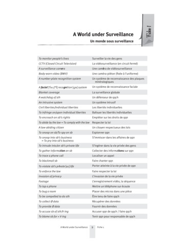
Part Ⅱ Environment Requirements for Software Running2.1 Operating system configuration32/64-bit simplified Chinese / English Windows 2000/2003/XP/Vista, Windows 7 and other operatingsystems.2.2 Minimum hardware configurationCPU: Pentium 2.0GHzMemory: 512 MBGraphics: TNT2Sound card: necessary for voice monitoring and two-way intercomHard disk: no less than 40G in case of recording images2.3 Recommended hardware configurationCPU: Intel Core2 Duo E7400 2.8GMemory: 2GGraphics: 128bit, 1GB memoryHard disk: SATA hard disk, over 8M cache, 2000G2.4 Software configurationIE 7.0 or above versionsDirectX9.0 or above versionsTCP / IP network protocolPart Ⅲ Software Installation and Uninstall3.1 Software accessPathway I: put the companion CD-ROM in the box of IP camera or video server into your computer'sCD-ROM drive, locate the setup file for the video surveillance management software, copy it to yourcomputer, double click it to run the installation; after installation, find the NVClient software under『Startmenu All programs NVClient V5』, or directly double-click “NVClient" on the desktop to run the mainprogram.Pathway II: contact our technical support department to transfer the video surveillance managementsoftware through remote QQ, MSN, E-mail or any other means.Pathway Ⅲ: Visit our official website to download from the Download Center.3.2 Software installationCheck and double-click the setup file of video surveillance management software, and the dialog box appears-2-
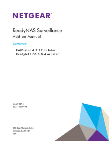
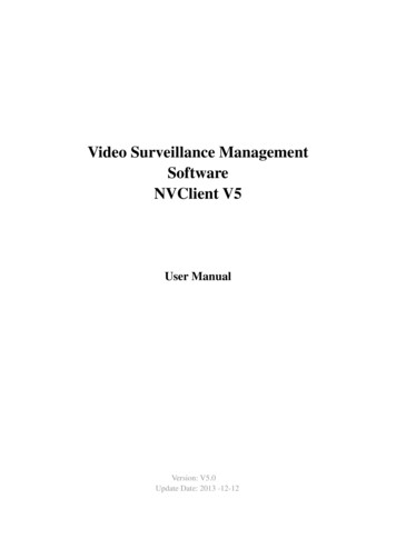
as shown below:Figure (1)Select the language you want to use in the installation: English、 简 体 中 文 、 Português、русский,click "OK"Follow the prompts and click "Next"Until the "Finish" button appears, click "Finish" to complete the installation.3.3 Removing the softwareThere are two ways to remove the video surveillance management software: On the Start menu, select "Programs" "NVClient V5” “Uninstall” to uninstall the software. Open the "Add / Remove Programs” dialog box on the "Control Panel"; in the list of programs,select to delete" NVClient Version "option.Delete the dialog box shown below:Figure (2)3.4 Software landingDouble-click the video surveillance management software iconof video surveillance management software, as shown below:-3-, then pop-up the Login dialog box
Figure (4)"User name" default: admin"Password" default: emptyCheck the "Remember Password" option; when re-entering the management software, there is no need tore-enter the password to log video surveillance management software interface.-4-
Part IV: Introduction of the Main InterfaceThe main interface of management software can only single-screen display up to 36-way image. You canmanually switch the pages as needed, or it can be set to automatically switch pages to polling the connectedchannels.Composition of the interface: System menu area, image preview window and status, standard toolbar area,equipment list area, Close and Minimize composition.4.1 System menu areaThe system menu area is described in the following table:IconTextReal-time previewVideo playbackFunction DescriptionClick this button to check video real-time previewClick this button to enter the video playback interface-5-
System configurationClick this button to enter the system configuration interface4.2 Device list areaThis area disp la ys th e added de viceThis area disp lays the added packe tinfo rmation, a s well a s pre view o pen o rdevicecloseplayerin formationandpacke t4.3 Standard toolbarThe standard toolbar is described as following:IconTextFunction DescriptionConnect the videoClick this button to connect the selected previewdeviceClick this button to turn off video preview of theTurn off the videoselected deviceClick this button to turn off video preview of allTurn off alldevices-6-
1 split screenVideo preview of 1 spilt screen window4 split screenVideo preview of 4 spilt screen window9 split screenVideo preview of 9 spilt screen window16 split screenVideo preview of 16 spilt screen window20 split screenVideo preview of 20 spilt screen window36 split screenVideo preview of 36 spilt screen windowMulti-image full-screenSequenceFull-screen previewGroup SequenceWindow toolbarToolbar for all windows, local zoom in, localzoom out, intercom, sound, video, capture, stoppreview playingCaptureClick this button to capture the selected image;the captured images will be stored in thespecified directory of the computerVideo recordingClick this button to turn on / off videoElectronic zoom outClick this button for electronic zoom outfunctionElectronic zoom inClick this button for electronic zoom in functionVoice intercomClick this button to turn on / off the voiceintercom functionSoundTwo states, Open / Close sound outputSound adjustmentAdjust the sound output sizeWindow controlWindow lock / minimize window / window close-7-
4.4 Shortcut functional areaThe shortcut functional area contains PTZ control, PTZ preset point, PTZcruise path and color settings.IconTextShrinkPTZ controlFunction DescriptionClose / open the PTZ controlPTZ controlPreset pointSet the PTZ preset position, call / remove PTZ presetpositionCruise pathSet the cruise pathColor settingsColor settings4.4.1 PTZ controlIconTextFunction DescriptionZoomEnlarge or reduce the video imageFocusAdjust the focal length of the lensApertureAdjust the size of the apertureDirectionControl PTZ up, down, left, right, automatic scanningWiperTurn on/off wiper functionLightTurn on / off lightPTZ speedAdjust the PTZ speed4.4.2 PTZ preset pointControl the PTZ function of the channel you choose in the view screen.-8-
Through the rotation of the direction key to control PTZcamera eight direction, by dragging to control PTZ rotationspeed.Click, PTZ will automatic scanning, the next click willstop the scanning.Click the right side of the function keys to adjust Zoom,Focus and Iris.IconTextFunction DescriptionZoomEnlarge or reduce the video imageFocusAdjust the focal length of the lensApertureAdjust the size of the apertureDirectionControl PTZ up, down, left, right, automatic scanningWiperTurn on/off wiper functionLightTurn on / off lightPTZ speedAdjust the PTZ speed4.4.3 PTZ preset point settingSupport 255 preset point setup and call.IconTextFunction DescriptionAdd preset pointRight click the preset point number to beadded, add the current preset position-9-
Call preset pointDouble click the preset point to call the setpreset position4.4.4 Cruise pathSet the cruise pathAdd 2 or more preset points to the view channel, you can set these preset points in a new cruise path.The interface is shown as in below.Step 1: Choose the channel which need set cruise path, clickin PTZ control panel, according to cruise path settingswindow.Step 2: Right click the cruise route name, click“Cruise routeconfiguration”, enter “Cruise route configuration”. Doubleclick also can enter “Cruise route configuration”.Step 3: Clickto add cruisepoint, in the preset point list you can choose thepreset point.Step 4: Set the preset point cruise time and speed.Clicksave add cruise point.Note: the range of cruise time: 1 3600seconds, cruising speed range of 1 7.- 10 -
Step 5: Repeat step 3 and step 4, add to cruise tocruise route list.Choose the cruise route you set, clickto call cruise route, clickto stop cruiseroute.4.4.5 Color settingsIconTextFunction DescriptionBrightnessAdjust the brightness of the front-end IPC,DVS, DVR video previewContrastAdjust the contrast of the front-end IPC, DVS,DVR video previewSaturationAdjust the saturation of the front-end IPC,DVS, DVR video previewSharpnessAdjust the sharpness of the front-end IPC,DVS, DVR video previewDefault valueDefault front-end IPC, DVS, DVR colorparameters- 11 -
IconTextFunction Description4.5 Preview WindowThe preview windows can be inter-exchanged.4.6 Alarm informationThe alarm information window displays motion detection, video loss, alarm input, other alarms and so on.You can query the relative types of alarm information.- 12 -
AlarmClose / open alarm information windowAlarm typeFind the corresponding alarmaccording to the alarm typeinformationPart V Detailed Description of the Software Function SetThe client management system features include several functional modules such as video playback, loopswitching, packet switching, equipment management, group management, basic configuration, usermanagement, remote setting and lock, which will be discussed one by one as follows.5.1 Video playbackVideo playback includes options like local playback, remote playback, type retrieval, time / file list retrieval,playback control, playback tool and multi-screen display.Function Description: Video playback can playback the video files, supports the multi-channel, multi-file,simultaneous playback and multi-screen display functions, and supports video retrieval.Function Introduction"Local playback": detect disk video files of the local computer and local video playback"Remote playback": test disk video files of the front-end equipment and local video playback“Type Search ": retrieve disk video files of the local computer or front-end equipment according to videofile types"Synchronous playback”: search playback and simultaneous playback by time- 13 -
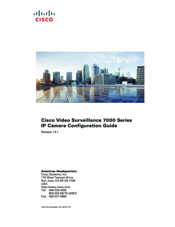
"Time / file list retrieval": search playback by time (zoom in and out by time,accurate to the second retrieval), select the desired playback time point by mouse to playback video.Search playback by file, select the desired playback video files to playback video."Playback Control"functions fromleft to right: previous file, frame rewind, play, pause, stop, frame forward, next file, playback speed.“Playback Tool"functions from left to right: add files, capture,video downloads, volume switch and volume size."Multi-screen display”: multi-screen playback display at the same time5.2 System ConfigurationThe system configuration features include options of remote configuration, device management, groupmanagement, basic configuration and user management.5.2.1 Basic configurationThis option is mainly focused on software configuration, video configuration, path configuration, and otherconfigurations, as shown in the following interface.- 14 -
Basic configuration described in the following table:ItemAlarmandoperationpreservation daysPower on automaticallyFunction DescriptionlogThis refers to the number of days that client generates alarminformation and operation information stored in the local log (default 30days)Select this item for the system to be restarted and automatically run theclient programFor example, preserving the recorded videos in C disk, as follows:"check" C disk, the system will create folder NVFile in the rootVideo storage pathdirectory of C disk, and all video files and other information concerningthe client software will be saved in this directory (saved in C disk bydefault)This item refers to the certain empty disk space to be reserved duringDisk reserved spacevideo recording; the default size is 10240MB; the minimum reservedspace is 10240MBVideo switching timeThis refers to the video package length of time; default 10 minutes togenerate a video file; switching time ranges from 10 minutes to 60- 15 -
minutesThis refers to the number of days for normal recording, motionPreservationdaysofnormalrecording and alarm recordingdetection recording and I / O alarm recording preserved in the local (theordinary recording default for 30 days, alarm recording is kept for 60days by default)This refers to the selection mode when the video storage disk is full inDisk full operationfiles; default in two ways: first, delete the oldest video files for looprecording when the disk is full; second, stop recording operationimmediately after the disk is fullRestore the preview stateCheck this item, re-visit the client, real-time preview the window, and itwill be restored to the preview state on exitLanguageSupport English, Simplified Chinese, Português, русский switchConfigureconfigure the PC COM port for keyboard configuration 3235.2.2 Device managementThis option focuses on the configuration of "device information", “area management” and so on. Theinterface is as follows:Device management is described in the following table:ItemFunction DescriptionArea addAdd new area informationArea modificationModify the name of the area has been addedArea deletionDelete the name of the area has been added- 16 -
SearchCheck “Search” to display the information of all devices in the LANType of deviceNetwork video device and P2P device to be selectedAdd a device manuallyAdd the specified device to the specified device area (double-click thedevice in the search list to add a device to the designated area)Bulk addSelect the box in front of the number, add all the searched deviceinformation to the specified area5.2.2.1 Steps for adding an areaStep 1: Click the Add button in area managementStep 2: Enter the name of the area for preservation- 17 -
5.2.2.2 Steps for manually adding network video devicesStep 1: Select the IP address of the device type, and then select the protocol type. A1: IPC Type A2: DVRType A3: TOPSEE protocol A4: ONVIF protocol;Step 2: Enter the name of the device (users can input any custom name in either Chinese or English)Step 3: Enter the address of the device in the address bar (you can fill in the IP address or domain name)Step 4: In the port number, set the device's data port number, DVS / IP Camera / default as 8200; this portcan be custom, filling in according to the data port in network settingsStep 5: Set the number of channels for front-end DVS / IP Camera (determined according to the channelnumber of front-end DVS / IP Camera)Step 6: Input the user name and password of front-end DVS / IP Camera (determined as the front-end device)Step 7: Click “Save” to complete adding the device- 18 -
5.2.2.3 Steps for manually adding P2P devicesStep 1: Select the device type P2PStep 2: Enter the name of the device (users can input any custom name in either Chinese or English)Step 3: Enter the name of the device in P2P device name (user-definable enter any name in English)Step4: Enter the P2P domain in the domain name, the domain name that is MY-EYE (MY-EYE domain canview the DDNS settings)Step 5: Set the number of channels for front-end DVS / IP Camera (determined according to the channelnumber of front-end DVS / IP Camera)Step 6: Input the user name and password of front-end DVS / IP Camera (determined as the front-end device)Step 7: Click “Save” to complete adding the device5.2.3 Group managementUser may set up more than one grouping as needed, grouping or loop switching display the videos; theinterface is as follows:- 19 -
Setup steps for group managementStep 1: Select the desired group for adding device; the maximum default of 10 groupsStep 2: Select a device channel in the device list, clickchannel in the selected group byto add a channel (remove the device)Step 3: Select group 1, right-click to modify the group information, set the residence time of a group, thenumber of split-screens, Allow polling and other parameters. The shortest switching time interval is 10S.5.2.4 RecordSet the record schedule- 20 -
Step 1: Choo se the d e vice you wan t sen t record , th is d evice.Step 2: S et the sche dule, NVClien t supp ort Max. 10 schedu le list.Step 3: S et the rec ord time in the schedu le. ( Monday to Sunda y)- 21 -
5.2.5 SchemeAlarm lin k set upStep 1: Choo se the d e vice you wan t set, checkStep 2: Choo se the c ha nnel o f the device, set alarm type.Step 3:Modify an d save th e setting .Lin k scheme se t upStep 1: Accord ing to th e de mand , you can cho ose scheme 1 to sch eme 10.Step 2: S et the ru le na me, p la y sound, d uratio n, reco rd, P TZ p reset p oint, pop u p video.- 22 -
5.2.6 User managementUsers can be given different operating authorities according to the actual needs of different users, theinterface as follows:- 23 -
Setup steps for a new user:Step 1: Select the “Add User” buttonStep 2: Set a new username and new passwordStep 3: Authorize the user specific operating authorityStep 4: Check the OK button to complete adding a new user. You can visit the client by this username foroperation.5.2.7 Remote setupRemote setup mainly focuses on the configuration of the parameters for various functions of the front-endequipment.For detailed configuration, refer to the user manual of video server and DVR.5.2.8 Log SearchUsers can search system log, alarm log and APP log information, as below shown.- 24 -
5.3 Group switchingThe user can set up multiple groups as needed for video group display or loop switching display.For detailed setting procedures of packet switching, please refer to section 5.2.3 --- Groupmanagement.Set up groups, select the group list in the real-time preview screen and right click the group list; the functions- 25 -
are as follows:ItemGrouping playFunction DescriptionManual grouping playCheck the residence time, number of split-screens and other relatedGrouping attributeinformation of group settingsPolling to this groupAllow polling in the group management, set the polling to this groupPart VI Video Surveillance Management Software FAQ6.1 Unable to access the network monitoring equipment through the video surveillance managementsoftwarePossible cause: no network?Solution: access the network by computer to test whether the network access is working properly; firsttroubleshoot the cable failure, network failure caused by computer viruses and firewall blocking until able toPing between the computers.Possible cause: IP address is occupied by other devices?Solution: disconnect the network monitoring device to the network, connect the network monitoring deviceto the computer separately, and then set the IP address following the correct operation.Possible cause: the computer's IP address and network equipment are located in different segments ordifferent subnets?Solution: check IP address, subnet mask and gateway settings.Possible cause: unknown?Solution: press the reset button on the server to restore to the factory default state, and then reconnect; defaultIP address for the DVS / IP Camera system is 192.168.1.100, subnet mask 255.255.255.0.6.2 Image display color is not normalPossible cause: poor site light?Solution: check whether the site ambient light is normal, increase auxiliary light source.Possible cause: the video frequency system setting is not correct?Solution: test whether the equipment video format (PAL or NTSC) is correct.Possible cause: bright color adjustable parameters are not set correctly?Solution: adjust the color values of the bright parameters depending on the site environment.6.3 PTZ camera cannot be controlledPossible cause: the signal cable is not connected or not connected properly?Solution: reconnect the control line that connects PTZ or dome camera to the server.Possible causes: not correctly set the corresponding decoder protocol, address or baud rate?- 26 -
Solution: please carefully check whether the settings are correct.Possible cause: the control line is too long?Solution: bold the control line.Possible cause: the equipment power is not enough?Solution: use the standard power adapter to increase power.6.4 No sound while monitoringPossible cause: no audio input device connected?Solution: check the audio connections.Possible cause: the audio option of the front-end device is not open?Solution: check the audio parameter settings of the front-end equipment to see if the audio is open.6.5 Audio ineffectivePossible cause: when the audio sounds to have a lot of cacophony and serious sound distortion, please checkwhether the input signal level is inputted from the line. Most of the time when the input signal is not inputtedfrom the line (such as a zoom back microphone), the server does not match the input level, resulting insaturation distortion.Solution: use the appropriate line input in accordance with the acceptable range of the video server.Part VII Factors that Affect System PerformanceWhen you build your system, you must consider the overall system performance, the factors that affect yoursystem, and how to set up your system to achieve optimal performance. The bandwidth issues are usuallyissues to consider, namely, how to set the bit rate, and other issues such as: frame rate issues; when the videosurveillance management software is connected too much, it will affect the frame rate of the server.The followings are some general factors for us to consider in the construction of the system, which mayaffect the server efficiency:1. First is the problem of your network bandwidth. It is usually OK for the LAN, but if it is WAN or anyprivate network, we must consider the network upload bandwidth. If the upload bandwidth is narrow, such asceiling 512kbps, you would rather not to set the server output stream over 512kbps, otherwise it will lead tothe phenomenon of audio or video interrupt.2. For the ADSL to be stressed, we usually concern about the downstream bandwidth of ADSL, but when weuse the video server, it is the upstream bandwidth to be used. At this time we should concern about itsupstream bandwidth when designing system, such as: for general ADSL2M, the downstream bandwidth isabout 1.5Mbps, but its upstream bandwidth is only 51
The video surveillance management software is used for achieving centralized monitoring, storage, management and control of all the front-end network video surveillance equipment (including network video server, network camera, and video decoder) and network video recorder (DVR). This management software