Transcription
Master’s ThesisTitleDesign principles for ISP networkswith consideration to overlay routing behaviorsSupervisorProfessor Masayuki MurataAuthorRyota FukumotoFebruary 14th, 2007Department of Information NetworkingGraduate School of Information Science and TechnologyOsaka University
Master’s ThesisDesign principles for ISP networks with consideration to overlay routing behaviorsRyota FukumotoAbstractIn recent years, network applications and services, such as P2P (Peer-to-Peer) file sharing,CDNs (Content Delivery Networks), and IP-VPNs (IP Virtual Private Networks), have been deployed over the Internet. These applications and services configure their own overlay networks.Each overlay network adopts its own routing algorithm to optimize users’ criteria. On the otherhand, the underlay network employs the IP routing. However, the IP routing does not necessarily take into account metrics for the overlay routing. That is why the overlay routing has beenconsidered.End users of overlay networks greedily choose better routes to optimize their own performancewithout considering the performance with regards to the network-wide criteria. Such selfish behaviors of end users cause unexpected increase of traffic volumes and traffic distributions on theunderlay network. Since the underlay network cannot directly control the behaviors of the endusers of overlay networks, it is important for network operators of underlay networks to appropriately design the networks by taking into account the selfish behavior of the overlay routing.In this thesis, we first evaluate the impact of the overlay routing’s selfish behavior on realisticrouter-level topologies from the perspective of maximum link load and average latency in thecase that the fixed shortest path routing is adopted for the underlay networks. The results of ourevaluation show that the overlay routing achieves near optimal latency but concentrates traffic oncertain links, when the overlay routing is at equilibrium. In addition, our results show that themaximum link load and the average latency in realistic router-level topologies which have thepower-law attribute are more affected by the overlay routing than those in POP level topologies.We next consider the case that the routes in underlay networks are dynamically updated againstthe change of link load. In such cases, the routing in overlay networks and that in the underlaynetworks interfere with each other. We then evaluate the impact of the interaction between the1
overlay routing and the routing in the underlay networks in realistic router-level topologies. Theresults indicate that the interaction makes the maximum link load be over 1.0. We then investigatethe impact of the interaction in cases that the number of nodes dynamically updating the routes inunderlay networks is limited. We examine where we should allocate the nodes that dynamicallyupdate the routes. The results shows that the maximum link load is decreased to 0.65 from 1.0when only the nodes classified as “provincial hubs” dynamically update the routes in the underlaynetworks against the change of link load.Based on this observation, we finally investigate the network design of ISP networks withconsideration to overlay routing behaviors. We then introduce overlay-optimal capacity designand compare the design to two conventional capacity designs in order to clear up which links weshould enhance in ISP topologies. The results show that we need to enhance the capacities ofsome links more than that of the conventional design if we consider the overlay routing behaviors.It also indicates that there exist nodes that have important roles for reducing the impact of theoverlay routing behavior.KeywordsOverlay routingISP networksPower-lawNetwork designRouter-level topologies2
Contents1 Introduction72 Network model2.12.210Underlay networks . . . . . . . . . . . . . . . . . . . . . . . . . . . . . . . . .102.1.1Physical topology . . . . . . . . . . . . . . . . . . . . . . . . . . . . . .102.1.2IP routing . . . . . . . . . . . . . . . . . . . . . . . . . . . . . . . . . .11Overlay networks . . . . . . . . . . . . . . . . . . . . . . . . . . . . . . . . . .132.2.1Logical topology . . . . . . . . . . . . . . . . . . . . . . . . . . . . . .132.2.2Overlay routing . . . . . . . . . . . . . . . . . . . . . . . . . . . . . . .133 Evaluation of overlay routings in power-law networks163.1Simulation model . . . . . . . . . . . . . . . . . . . . . . . . . . . . . . . . . .163.2Evaluation metrics . . . . . . . . . . . . . . . . . . . . . . . . . . . . . . . . .173.3Evaluation and discussions . . . . . . . . . . . . . . . . . . . . . . . . . . . . .173.3.1Maximum link load . . . . . . . . . . . . . . . . . . . . . . . . . . . . .173.3.2Average latency . . . . . . . . . . . . . . . . . . . . . . . . . . . . . . .183.3.3Maximum link load versus average link load . . . . . . . . . . . . . . .183.3.4Distribution of link load . . . . . . . . . . . . . . . . . . . . . . . . . .214 Interaction between overlay routing and underlay routing254.1Interaction between two routing algorithms . . . . . . . . . . . . . . . . . . . .254.2Simulation model . . . . . . . . . . . . . . . . . . . . . . . . . . . . . . . . . .254.3Evaluations and discussions . . . . . . . . . . . . . . . . . . . . . . . . . . . . .254.3.1Evaluation results . . . . . . . . . . . . . . . . . . . . . . . . . . . . . .264.3.2Classification of node function . . . . . . . . . . . . . . . . . . . . . . .265 Design principles with consideration to overlay routing315.1Approaches for capacity design in ISP networks . . . . . . . . . . . . . . . . . .315.2Evaluations and discussions . . . . . . . . . . . . . . . . . . . . . . . . . . . . .335.2.1Network performance . . . . . . . . . . . . . . . . . . . . . . . . . . .335.2.2Characteristic of link capacity . . . . . . . . . . . . . . . . . . . . . . .373
6 Conclusion39Acknowledgments40References424
List of Figures1Degree distribution of each topologies . . . . . . . . . . . . . . . . . . . . . . .122Network model . . . . . . . . . . . . . . . . . . . . . . . . . . . . . . . . . . .143Maximum link load versus overlay traffic factor . . . . . . . . . . . . . . . . . .194Average latency versus overlay traffic factor . . . . . . . . . . . . . . . . . . . .205Maximum link load versus average link load . . . . . . . . . . . . . . . . . . . .216Distribution of link load . . . . . . . . . . . . . . . . . . . . . . . . . . . . . . .237Corelation between the link load with minimum hop routing and with overlay routing 248The maximum link load:source routing nodes are located by descending order ofthe degree . . . . . . . . . . . . . . . . . . . . . . . . . . . . . . . . . . . . . .927Classification of node function with participation coefficient and within moduledegree . . . . . . . . . . . . . . . . . . . . . . . . . . . . . . . . . . . . . . . .2810Classification of node function in each topology . . . . . . . . . . . . . . . . . .2911Approache for capacity design . . . . . . . . . . . . . . . . . . . . . . . . . . .3212Maximum link load in each topology . . . . . . . . . . . . . . . . . . . . . . . .3413Average latency of overlay traffic in each topology . . . . . . . . . . . . . . . .3514Average latency of non ovelay traffic in each topology . . . . . . . . . . . . . . .3615Capacity ratio of the overlay optimal design to the conventional design . . . . . .385
List of Tables1The number of nodes and links in each topology . . . . . . . . . . . . . . . . . .611
1 IntroductionIn recent years, network applications and services, such as P2P (Peer-to-Peer) file sharing, CDNs (Content Delivery Networks), and IP-VPNs (IP Virtual Private Networks), have been deployed over theInternet. These applications and services configure their own overlay networks; nodes in the overlay networks are connected with logical links through one or more links in the underlay networks,which we assume IP networks. Each overlay network adopts its own routing algorithm to optimize users’ criteria, such as latency and the other QoS (Quality of Service) metrics, which we calloverlay routing. On the other hand, the underlay network employs the IP routing. That aims tominimize a hop distance of routes or minimizes the maximum link load for traffic engineering [1].The IP routing does not necessarily take into account metrics for the overlay routing.Overlay networks allow end users to control routes to other nodes in order to satisfy theirQoS requirements. Therefore, end users of overlay networks greedily choose better routes tooptimize their own performance without considering the performance with regards to the networkwide criteria. Such selfish behaviors of end users cause unexpected increase of traffic volumesand traffic distributions on the underlay network. Since the underlay network cannot directlycontrol the behaviors of the end users of overlay networks, it is important for network operators ofunderlay networks to appropriately design the networks by taking into account the selfish behaviorof the overlay routing.Roughgarden et al. take a theoretical approach to evaluate the performance of a selfish routing,in which users select their routes selfishly [2]. They point out that the average latency is degradedseriously when each of end users ignores latencies of the other users and selfishly chooses moreoptimal routes for themselves. However, Qiu et al. show that the overlay routing may achieve nearoptimal latency at equilibrium (the difference between the overlay routing and a latency optimalrouting is usually close to 0 and is always within 30%), while the links in the underlay networksare significantly congested [3]. In Ref. [3], Qiu et al. use POP (Point of Presence) level networksas Internet-like environments. That is, they only show a possible application of overlay routingto networks which have at most 100 nodes. However, since the users of overlay networks aredistributed all over the Internet, overlay networks are generally widespread over the large area ofthe Internet. More importantly, it is known that the degree distribution of nodes in the Internetexhibits the power-law attribute [4]. However, the POP level topologies discussed in [3] have too7
small number of nodes to reflect the power-law attribute. Therefore, it is important to show theperformance of overlay routing on more Internet-like network topologies in terms of the numberof nodes and the power-law attribute.In this thesis, we first evaluate the impact of the overlay routing’s selfish behavior on realisticrouter-level topologies from the perspective of maximum link load and average latency in thecase that the fixed shortest path routing is adopted for the underlay networks. The results of ourevaluation show that the overlay routing achieves near optimal latency but concentrates traffic oncertain links, when the overlay routing is at equilibrium. In addition, our results show that themaximum link load and the average latency in realistic router-level topologies which have thepower-law attribute are more affected by the overlay routing than those in POP level topologies.That is, much more traffic concentrates on certain links in the realistic router-level topology bythe overlay routing. We also demonstrate that the overlay routing achieve higher maximum linkload and latency, when the overlay routing is at non-equilibrium due to the oscillation of routes inoverlay networks.We next consider the case that the routes in underlay networks are dynamically updated againstthe change of link load. In Ref. [1], an IP routing that dynamically updates the routes against thechange of link load is studied. In such cases, the routing in overlay networks and that in theunderlay networks interfere with each other. In Ref. [5], Liu et al. evaluate the impact of aninteraction between the overlay routing and the traffic engineering in the underlay networks. Theauthors reveal the possibility of the performance degradation of both of the overlay and underlaynetworks due to the interaction. However, they evaluate the influence of the interaction with onlya small size topology that has 14 nodes. We again evaluate the impact of the interaction betweenthe overlay routing and the routing in the underlay networks in realistic router-level topologies.The results indicate that the interaction makes the maximum link load be over 1.0. That is, theinteraction between the overlay and underlay networks degrades the network performance. Inorder to relax the degradation of the network performance due to the interaction, we investigatethe impact of the interaction in cases that the number of nodes dynamically updating the routesin underlay networks is limited. Due to this limitation we can expect that the magnitude of theinteraction gets smaller and the convergence time of the overlay and underlay routing gets shorter.However, it is more important to show where we should allocate such nodes. We then examinewhere we should allocate the nodes that dynamically update the routes. The results shows that8
the maximum link load is decreased to 0.65 when only the nodes classified as “provincial hubs”dynamically update the routes in the underlay networks against the change of link load, whichindicates that the overlay routing and the underlay routing can coexist.Overlay routing has the huge influence on the network design because such routing is uncontrollable for network operators. If we understand overlay routing’s behaviors, we can use theinsights for network design. Hence, based on this observation, we finally investigate the network design of ISP networks with consideration to overlay routing behaviors. We then introduceoverlay-optimal capacity design and compare the design to two conventional capacity designs inorder to clear up which links we should enhance in ISP topologies. We show that not only thenodes classified as “connector nodes” but also the nodes classified as “peripheral nodes” haveimportant roles for reducing the impact of the overlay routing behaviors.This thesis is organized as follows. Section 2 shows the network model that we use for ourevaluation. In Section 3, we evaluate the performance of the overlay routing on ISP topologies.Next in Section 4, we evaluate the influence of the interaction of the overlay routing and theunderlay routing in ISP networks. In Section 5, we evaluate capacity design on ISP topologies.Finally, Section 6 concludes our thesis and mentions the future work.9
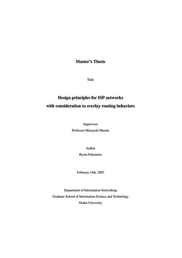
2 Network modelIn this section, we show the network model that we use for our evaluations. We first show theunderlay networks that we assume, IP networks. We next show the overlay networks that weassume.2.1 Underlay networksIn the following sections, we show about underlay networks that we asumme, IP networks. Wefirst show about the physical topologies. We next show about routings in the underlay networks,IP routing.2.1.1 Physical topologyRecent measurement studies on Internet topology show that the connectivity of nodes exhibit apower-law attribute (e.g., see [4], [6]). That is, the probability p(k), that a node is connectedto k other nodes, follows p(k) k γ . In recent years, considerable numbers of studies haveinvestigated power-law networks whose degree distributions follow the power-law [7–11]. Here,the degree is defined as the number of out–going links at a node. The theoretical foundation for thepower–law network is introduced in Ref. [12] where they also presents the BA (Barabashi-Albert)model in which nodes increase incrementally and links are placed based on the connectivity oftopologies in order to form power–law networks. The resulting power-law networks have twomain characteristics: (1) a small number of links are connected with numerous nodes, while alarge number of links are connected with a few nodes, and (2) the number of hop-counts betweennodes is small (small–world property).However, even if the degree distributions of some topologies are the same, more detailed characteristics are often quite different. A work by Li et al. [13] has enumerated various topologieswith the same degree distributions, and has shown the relation between the characteristics and performances of these topologies, throughput and likelihood metrics. With the technology constraintsimposed by routers, the degree of nodes limits the capacity of links that are connected to. Li etal. therefore point out that higher–degree nodes tend to be located at the edges of a network, andlower-degree nodes tend tot be located at the core of a network. That is, they point out that thestructure of a topology generated by BA model is different from that of ISP topologies. As for the10
Table 1: The number of nodes and links in each 0412801280throughput and link load properties when applying routing, it is shown that a topology generatedby BA model have different property from ISP topologies in [14].In order to evaluate overlay routing behaviors in ISP topologies, we therefore use three ISProuter-level topologies. The topologies are Sprint topology and AT&T topology measured inRef. [15]. Sprint and AT&T are major ISP in United States. We call these topologies the Sprinttopology, the AT&T topology, and the Verio topology respectively. The Sprint topology has 467nodes and 1280 links. The AT&T topology has 523 nodes and 1304 links. The Figs. 1(a) and 1(b)represent the degree distribution of each topology. The figures show that these topologies certainlyhave power-law like distribution. That is, the distributions can be approximated by straight lines.We also use BA topology generated by the BA (Barabashi-Albert) model [12], and ER topology generated by ER (Erdos-Renyi) model [16] for comparison. In ER model, links are randomlyplaced between nodes. We call these topologies the BA topology, and the ER topology respectively. The Figs. 1(c) and 1(d) show the degree distribution of these two topologies. In the figure,we can see that the BA topology has power-law degree distribution and the ER topology has Poisson degree distribution. These topologies are generated such that the numbers of nodes and linksare the same as that for the Sprint topology. These all topologies consist of nodes and links shownin Table 1.2.1.2 IP routingIn underlay networks, traffic is transferred with IP routing. In our thesis, we consider a staticrouting and a dynamic routing. As static routing, we assume that traffic is transferred to minimizehop-counts between a source node and a destination node. We call this routing the minimum hoprouting. As for the dynamic routing, we assume the routing that dynamically controls routes ofthe IP packets to detour congested links. We call this routing the dynamic IP routing. We callthe nodes which dynamically controls routes “source routing nodes”. Each dynamic routing node11
a) The Sprint topology10Degree100(b) The AT&T ree1001(c) The BA topology10Degree(d) The ER topologyFigure 1: Degree distribution of each topologies12100
determines routes using Dijkstra’s shortest path algorithm. In detail, the nodes assign the cost oflink l, Wl as Wl 1/(Cl fl ). Here, Cl is the capacity of link l, fl is the amount of trafficwhich pass through link l. As fl closes to Cl , Wl increases. Each dynamic routing node thencan avoid congested links. Note that the nodes explicitly specify the routes of traffic generated onthem (source routing). If a source routing node determines a route of the traffic, the node specifiesall nodes that the traffic passes through.2.2 Overlay networksIn the following sections, we show overlay network model that we assume. We first show aboutlogical topologies. We next show about routings in the overlay networks, overlay routing.2.2.1 Logical topologyOverlay network constructs logical topologies. Logical topologies consist of overlay nodes andlogical links which connect between overlay nodes. Logical links consist of one or more physicallinks. Physical links which compose a logical link is depend on network level routing, IP routing.For instance, when we assume that the network level routing uses minimum hop routing, the logical link (a0 , d0 ) consists of the physical link (a, e) and (e, d) as shown in Figure 2. If the networklevel routing is dynamic, the physical links which compose the logical link (a0 , d0 ) changes asoften as the routing changes routes.In our evaluations, we assume that overlay nodes are fully connected as shown in Figure 2. Itmay be unrealistic that overlay nodes are fully connected. However, we can expect to evaluate theresult got when overlay networks are constructed optimally.2.2.2 Overlay routingWe assume that two types of traffic occur in networks. One is non-overlay traffic. Non-overlaytraffic is stationary and transferred by IP routing. The other is overlay traffic. Overlay trafficis transferred by overlay nodes. Each overlay node transmits overlay traffic generated on eachoverlay node to another overlay node such that each overlay node maximizes its own metrics. Inreal networks, each overlay node measures the quality of logical links or paths. Since overlaynodes generally cannot know the states of physical network (e.g., physical links that compose a13
Figure 2: Network modellogical links), overlay nodes determine routes of overlay traffic by using only qualities of logicallinks or paths.In our evaluations, we assume that each overlay node explicitly specifies logical path of trafficgenerated at the node (source routing). That is, if an overlay routing node determines a route ofthe overlay traffic, the overlay node specifies all overlay nodes that the traffic passes through.In our evaluations, we consider two kinds of overlay routings. One is the overlay routing whichaims to minimize the end-to-end delay. This type of overlay routing is assumed in [3]. The otheris the overlay routing which is managed by the network operator in order to avoid congestionsand to improve resilience (e.g., RON [17]). In our thesis, we call these overlay routings “Useroriented overlay routing” and “Network-oriented overlay routing”. That is, we consider not onlyan overlay routing which aims to improve the user-wide criteria but also an overlay routing whichaims to improve the network-wide criteria. Note that not only nodes that use the user-orientedoverlay routing, but also nodes that use the network-oriented overlay routing does not considerwith other overlay nodes. We then compare and evaluate these overlay routing.14
User-oriented overlay routing The user-oriented overlay routing assumes that end users controlroutes considering their own metrics. With the user-oriented overlay routing, each overlay node(end user) transmits traffic generated on itself. The overlay nodes specify all overlay nodes thatexist on the way to the destination node in order to optimize their own metrics. The metric isthe average end-to-end delay of the traffic. They change their routes selfishly and dynamically.Therefore overlay nodes keep changing their routes until they can find more effective routes. Here,we define equilibrium as a state where no overlay node can improve their metrics by changing theamount of traffic which it sends along different logical paths. That is, overlay nodes keep changingtheir routes until the network state becomes equilibrium.Network-oriented overlay routing We introduce the network-oriented overlay routing. Thisoverlay routing assumes that routers control routes considering their own metrics. But the metricsare network costs. We define the network cost as the following function.X1/(Cl fl )lHere, Cl is a capacity of link l, fl is the amount of flow on link l. The overlay nodes changetheir routes without cooperating with the other overlay nodes. Therefore the overlay nodes keepchanging their routes while they can find more effective routes.Network-oriented optimal overlay routing As well as above-mentioned two overlays routing,we introduce the network-oriented optimal overlay routing for comparison. With the networkoriented overlay routing, each overlay node selfishly controls routes of traffic considering the network cost. However, with the network-oriented optimal overlay routing, overlay nodes cooperatewith each other. The network-oriented optimal overlay routing therefore can optimize the networkcost. However we consider this overlay routing for comparison with the network-oriented overlayrouting.15
3 Evaluation of overlay routings in power-law networksWe apply the above-mentioned overlay routings to power-law networks. As mentioned above,overlay routing changes routes dynamically. So we evaluate the overlay routings by computingtheir performance at equilibrium similarly in Ref. [3]. We use the flow deviation method (FrankWolfe algorithm) [18] to compute their performance at equilibrium. We then evaluate maximumlink load and average latencies at equilibrium. We also evaluate overlay routings when overlaynodes change routes periodically, overlay nodes change their routes at the same time, in order tocompare with the overlay routing at equilibrium.3.1 Simulation modelWe use the Sprint topology and the AT&T topology as ISP topologies. We also use BA topologyand ER topology for comparison. In our evaluation, we assume that each node-pair generates thesame amount of traffic at a unit time and all nodes are overlay nodes. We also assume that all linkshave 10 Gbps capacity and that the propagation delay of all links is 1 msec. Because we focuson the link load property, we set the processing delay on nodes 0 msec. Therefore the latency isthe total of propagation delays and transmission delays on links. As for network level routing, weconsider the minimum hop routing. Logical links of overlay networks are decided by minimumhop routing.Computing equilibrium with the flow deviation methodAs mentioned above, we use the flow deviation method to compute the equilibrium of overlayroutings. The flow deviation method incrementally changes the flow assignment along feasibleand descent directions. Given objective function T , the method set we as a partial derivative withrespect to Fe , where Fe is the amount of traffic that traverses link l. Then, the new flow assignmentis solved by using the shortest path algorithm in terms of we . By incrementally changing fromthe old to the new flow assignment, optimal flow assignment is determined. We compute theequilibrium of overlay routings with this method. In this thesis, we set objective function T toTu Tn XZXZle (xe )dx (U ser oriented)e(1/(Ce xe ))dx (N etwork oriented)e16
To X1/(Ce xe ) (N etwork orientedoptimal)ewhere Ce is the capacity of link e, xe is amount of traffic on link e, and le is latency on link e.3.2 Evaluation metricsIn this section, we evaluate the following two metrics. One is maximum link load. In this thesis,we define the link load of link i as Fi /Ci . We then define the maximum link load as the maximalvalue of link loads in the network. We also use the average latency in the network as evaluationmetrics.3.3 Evaluation and discussionsIn following sections, we evaluate the overlay routings on ISP topologies using above mentionedmetrics. We first focus on the maximum link load on the topologies. We next investigate theaverage latency of overlay traffic. We then evaluate link loads in more detail.3.3.1 Maximum link loadWe show the maximum link load for representative topologies, as we vary the overlay traffic factorin Figure 3. The vertical axis represents maximum link load in the topologies. The horizontal axisrepresents overlay traffic factor. Overlay traffic factor represents the amount of traffic generatedon the overlay network. When the overlay traffic factor is 1.0, the amount of overlay traffic equalsto the amount of traffic generated on the physical network, non overlay traffic. In our evaluations,we set the amount of non overlay traffic to the amount which maximum link load achieves 0.5with the network level routing.We can make the following observations. At first, 3(c), we can confirm that the networkoriented overlay routing achieves much lower maximum link load than the user-oriented overlayrouting in Figs. 3(a), 3(b). We can also confirm that the network-oriented overlay routing canachieve maximum link load equivalent to that of the network-oriented optimal overlay routing.The similar observations are shown on the Sprint POP level topology (Ref. 3(e)).On the other hand, we can confirm that the overlay routings at equilibrium achieve almost thesame maximum link loads in the ER topology (Ref. 3(d)). This is due to the difference between thestructure of the ER topology and that of the other topologies. As indicated in [14], the ER topology17
decentralizes link loads with the minimum hop routing while the other topologies concentrate linkload to some links. That is, almost all links have a certain level of load. Therefore the ER topologyhardly has links for the overlay routings to use for diverting traffic.3.3.2 Average latencyWe next show the average latency for representative topologies, as we vary the overlay trafficfactor in Figure 4. The vertical axis represents the average latency of all node pair. The horizontalaxis represents overlay traffic factor. We can confirm that the average latencies are about thesame with any overlay routings. We therefore can say that the network-oriented overlay routing,which aims to decentralize the link loads, achieves much lower maximum link load than the useroriented overlay routing, which aims to lower the average latency, while keeping the averagelatency approximately equivalent to that of the user-oriented overlay routing.These results are got by computing the equilibrium. However, these overlay routings don’talways converge to the equilibrium in the Internet
Based on this observation, we finally investigate the network design of ISP networks with consideration to overlay routing behaviors. We then introduce overlay-optimal capacity design and compare the design to two conventional capacity designs in order to clear up which links we should enhance in ISP topologies.