Transcription
BullStorage Area Network (SAN)Installation and Configuration GuideAIXORDER REFERENCE86 A2 57EF 01
BullStorage Area Network (SAN)Installation and Configuration GuideAIXSoftwareFebruary 2002BULL CEDOC357 AVENUE PATTONB.P.2084549008 ANGERS CEDEX 01FRANCEORDER REFERENCE86 A2 57EF 01
The following copyright notice protects this book under the Copyright laws of the United States of Americaand other countries which prohibit such actions as, but not limited to, copying, distributing, modifying, andmaking derivative works.CopyrightBull S.A. 1992, 2002Printed in FranceSuggestions and criticisms concerning the form, content, and presentation ofthis book are invited. A form is provided at the end of this book for this purpose.To order additional copies of this book or other Bull Technical Publications, youare invited to use the Ordering Form also provided at the end of this book.Trademarks and AcknowledgementsWe acknowledge the right of proprietors of trademarks mentioned in this book.AIXR is a registered trademark of International Business Machines Corporation, and is being used underlicence.UNIX is a registered trademark in the United States of America and other countries licensed exclusively throughthe Open Group.The information in this document is subject to change without notice. Groupe Bull will not be liable for errorscontained herein, or for incidental or consequential damages in connection with the use of this material.
PrefaceWho should read this bookThis book is intended for readers who are not familiar with Storage Area Network (SAN) butwho need to install a SAN on their IT system. The first three chapters provide anintroduction to SAN technology, infrastructure, and components. The next two chaptersdescribe how to design a SAN and how to install the Bull SAN. The last chapter containstechnical details of internal SAN software operation.The book is organized as follows: Chapter 1. Introduction Chapter 2. SAN Infrastructure Chapter 3. SAN Components Chapter 4. SAN Methodology Chapter 5 SAN Installation Chapter 6. How the OS handles SAN Objects Glossary IndexRelated PublicationsCabling Guide for Multiple Bus system,86A170JXSite Monitoring for Disaster Recovery,86A283JXRecovery from Cluster Site Disaster User’s Guide,86A286JXDASDAS Subsystems – DAE Rackmount Models – Installation and Service, 86A145KXDAS Subsystems – DAE Deskside Models – Installation and Service,86A146KXDAS4500 Deskside Models – Installation and Service,86A101EFDAS4500 Rackmount Models – Installation and Service,86A102EFDAS4700 Hardware Reference,86A170EFDAS4700–2 Rackmount Model Hardware Reference,86A185EFDAS4700–2 Configuration Planning Guide,86A186EFDAS5300 Deskside Models – Installation and Service,86A101EFDAS5300 Rackmount Models – Installation and Service,86A102EFDAS5700 Series Standby Power Supply (SPS) –Installation and Service,86A148KXDAS Subsystems DC SPS (Direct Current Standby Power Supply) –Installation and Service,86A120KXPlanning a DAS Installation – Fibre Channel Environments,86A194JXDAS – Configuring and Managing a DAS – AIX Server Setup,86A220PNDAS – Navisphere for AIX – Setup and Operation,86A247KXPrefaceiii
Navisphere Manager Installation and Operation86A204EFNavisphere 4.X Supervisor Installation and Operation86A205EFEMC Navisphere 4X Agent Installation069000880EMC Navisphere ATF069000980Fibre Channel adapterPCI Fibre Channel Adapters Installation and Configuration Guide86A195HXS@N.IT! V2 (formerly known as ASM)S@N.IT! User’s Guide86A259EFSRB86A286EESilkworm 2000 Entry Family53–0000010Silkworm 2800 Hardware Reference Manual53–0001534Fabric OS TM Version 2.253–0001560BrocadeFabric OSTM Version2.053–0001535SymmetrixSymmetrix Storage Reference Guide86A185KXPowerPath V2.0 for Unix Installation Guide300–999–266Volume Logix V 2.3 Product Guide300–999–024EMC Fibre Channel Interface V2.0 for AIX Product Guide200–999–642SymmWin V5.0 Product Guide300–999–074Conn Enterprise Storage Network System, Topology Guide300–600–008Enterprise Fibre Director Model 1032 User’s Guide300–600–004EMC ControlCenter Integration Package for Windowsand Unix Version 4.1 Product Guide300–999–087Microsoft Windows NTServer SetupivSAN Installation & Configuration Guide014002899
Table of ContentsPreface . . . . . . . . . . . . . . . . . . . . . . . . . . . . . . . . . . . . . . . . . . . . . . . . . . . . . . . . . . . . . . . .iiiChapter 1. Introduction to Storage Area Networking . . . . . . . . . . . . . . . . . . . . . . .Overview . . . . . . . . . . . . . . . . . . . . . . . . . . . . . . . . . . . . . . . . . . . . . . . . . . . . . . . . . . . . . . .Challenges and Risks . . . . . . . . . . . . . . . . . . . . . . . . . . . . . . . . . . . . . . . . . . . . . . . . . . . .SAN management . . . . . . . . . . . . . . . . . . . . . . . . . . . . . . . . . . . . . . . . . . . . . . . . . . . . . . .1-11-11-31-3Chapter 2. SAN Infrastructure . . . . . . . . . . . . . . . . . . . . . . . . . . . . . . . . . . . . . . . . . . .Media speed . . . . . . . . . . . . . . . . . . . . . . . . . . . . . . . . . . . . . . . . . . . . . . . . . . . . . . . . . . . .Cabling . . . . . . . . . . . . . . . . . . . . . . . . . . . . . . . . . . . . . . . . . . . . . . . . . . . . . . . . . . . . . . . . .FC Networks . . . . . . . . . . . . . . . . . . . . . . . . . . . . . . . . . . . . . . . . . . . . . . . . . . . . . . . . . . . .Point–to–point connection . . . . . . . . . . . . . . . . . . . . . . . . . . . . . . . . . . . . . . . . . . . . . .Loops and hubs . . . . . . . . . . . . . . . . . . . . . . . . . . . . . . . . . . . . . . . . . . . . . . . . . . . . . . .Fabrics and switches . . . . . . . . . . . . . . . . . . . . . . . . . . . . . . . . . . . . . . . . . . . . . . . . . . .Interconnection of fabrics and loops . . . . . . . . . . . . . . . . . . . . . . . . . . . . . . . . . . . . . .Zoning, switched loops, mixed private loops and fabrics . . . . . . . . . . . . . . . . . . . . . . .Fabric zoning . . . . . . . . . . . . . . . . . . . . . . . . . . . . . . . . . . . . . . . . . . . . . . . . . . . . . . . . .Loop zoning . . . . . . . . . . . . . . . . . . . . . . . . . . . . . . . . . . . . . . . . . . . . . . . . . . . . . . . . . .Switched loop . . . . . . . . . . . . . . . . . . . . . . . . . . . . . . . . . . . . . . . . . . . . . . . . . . . . . . . . .Mixing private loops and fabrics . . . . . . . . . . . . . . . . . . . . . . . . . . . . . . . . . . . . . . . . .Interconnection with Legacy Technologies . . . . . . . . . . . . . . . . . . . . . . . . . . . . . . . . . . .FC/SCSI bridges . . . . . . . . . . . . . . . . . . . . . . . . . . . . . . . . . . . . . . . . . . . . . . . . . . . . . .FC/IP bridges . . . . . . . . . . . . . . . . . . . . . . . . . . . . . . . . . . . . . . . . . . . . . . . . . . . . . . . . .FC/WAN bridges . . . . . . . . . . . . . . . . . . . . . . . . . . . . . . . . . . . . . . . . . . . . . . . . . . . . . -8Chapter 3. SAN Components . . . . . . . . . . . . . . . . . . . . . . . . . . . . . . . . . . . . . . . . . . . .SAN hardware components . . . . . . . . . . . . . . . . . . . . . . . . . . . . . . . . . . . . . . . . . . . . . . .SAN software components . . . . . . . . . . . . . . . . . . . . . . . . . . . . . . . . . . . . . . . . . . . . . . . .FC driver . . . . . . . . . . . . . . . . . . . . . . . . . . . . . . . . . . . . . . . . . . . . . . . . . . . . . . . . . . . . .DAS software products . . . . . . . . . . . . . . . . . . . . . . . . . . . . . . . . . . . . . . . . . . . . . . . . .Symmetrix software products . . . . . . . . . . . . . . . . . . . . . . . . . . . . . . . . . . . . . . . . . . . . . .Brocade Silkworm Software . . . . . . . . . . . . . . . . . . . . . . . . . . . . . . . . . . . . . . . . . . . . . . .S@N.IT! (formerly known as ASM) . . . . . . . . . . . . . . . . . . . . . . . . . . . . . . . . . . . . . . . . .Hardware and software minimum requirements . . . . . . . . . . . . . . . . . . . . . . . . . . . . . .3-13-13-43-43-43-53-63-63-8Chapter 4. Methodology to Build SAN Configurations . . . . . . . . . . . . . . . . . . . . .Overview . . . . . . . . . . . . . . . . . . . . . . . . . . . . . . . . . . . . . . . . . . . . . . . . . . . . . . . . . . . . . . .Step 1 Collect the Data . . . . . . . . . . . . . . . . . . . . . . . . . . . . . . . . . . . . . . . . . . . . . . . . . . .1.1 Identify all the servers, applications, and data–sets . . . . . . . . . . . . . . . . . . . . .1.2 Get characteristics of each data–set . . . . . . . . . . . . . . . . . . . . . . . . . . . . . . . . . .Step 2 Size the Servers and Storage Systems . . . . . . . . . . . . . . . . . . . . . . . . . . . . . . .2.1 Create connectivity matrix and data–set maps . . . . . . . . . . . . . . . . . . . . . . . . .2.2 Configure each disk array . . . . . . . . . . . . . . . . . . . . . . . . . . . . . . . . . . . . . . . . . . .2.3 Identify hot–spots . . . . . . . . . . . . . . . . . . . . . . . . . . . . . . . . . . . . . . . . . . . . . . . . . .2.4 Configure the libraries . . . . . . . . . . . . . . . . . . . . . . . . . . . . . . . . . . . . . . . . . . . . . .Step 3 Design the SAN Topology . . . . . . . . . . . . . . . . . . . . . . . . . . . . . . . . . . . . . . . . . .3.1 Start with an empty map . . . . . . . . . . . . . . . . . . . . . . . . . . . . . . . . . . . . . . . . . . . .3.2 Analyze the structure of the SAN to be designed . . . . . . . . . . . . . . . . . . . . . . .3.3 Interconnect hardware according to your connectivity matrix . . . . . . . . . . . . .3.4 Check performance constraints . . . . . . . . . . . . . . . . . . . . . . . . . . . . . . . . . . . . . acev
viStep 4 Check Operational Constraints . . . . . . . . . . . . . . . . . . . . . . . . . . . . . . . . . . . . . .4.1 Identify zones to be defined in the SAN . . . . . . . . . . . . . . . . . . . . . . . . . . . . . . .4.2 Specify the LUN management tools . . . . . . . . . . . . . . . . . . . . . . . . . . . . . . . . . .4.3 Check multipathing risks . . . . . . . . . . . . . . . . . . . . . . . . . . . . . . . . . . . . . . . . . . . .4.4 Consolidate all the information . . . . . . . . . . . . . . . . . . . . . . . . . . . . . . . . . . . . . . .Step 5 Determine a Management Policy . . . . . . . . . . . . . . . . . . . . . . . . . . . . . . . . . . . .5.1 Draw the management infrastructure . . . . . . . . . . . . . . . . . . . . . . . . . . . . . . . . .Step 6 Write a Consolidated Report . . . . . . . . . . . . . . . . . . . . . . . . . . . . . . . . . . . . . . . .4-64-64-64-64-64-74-74-7Chapter 5. Installing a SAN . . . . . . . . . . . . . . . . . . . . . . . . . . . . . . . . . . . . . . . . . . . . . .Before Installing a SAN . . . . . . . . . . . . . . . . . . . . . . . . . . . . . . . . . . . . . . . . . . . . . . . . . . .SAN Installation Overview . . . . . . . . . . . . . . . . . . . . . . . . . . . . . . . . . . . . . . . . . . . . . . . .Step 1: Install software and FC adapters on servers . . . . . . . . . . . . . . . . . . . . . . . . . .Installation on AIX Servers . . . . . . . . . . . . . . . . . . . . . . . . . . . . . . . . . . . . . . . . . . . . . .Installation on Windows NT servers . . . . . . . . . . . . . . . . . . . . . . . . . . . . . . . . . . . . . .Step 2: Setup the central S@N.IT! server and GUI . . . . . . . . . . . . . . . . . . . . . . . . . . .Step 3: Install the SAN management software on servers . . . . . . . . . . . . . . . . . . . . .Step 4: Install the storage subsystems . . . . . . . . . . . . . . . . . . . . . . . . . . . . . . . . . . . . . .Step 5: Install and set–up switches (SAN in fabric topology) . . . . . . . . . . . . . . . . . . .Step 6: Physical connection and configuration of FC links . . . . . . . . . . . . . . . . . . . . .Step 7: Setup the storage subsystems . . . . . . . . . . . . . . . . . . . . . . . . . . . . . . . . . . . . . .DAS subsystem setup . . . . . . . . . . . . . . . . . . . . . . . . . . . . . . . . . . . . . . . . . . . . . . . . . .Symmetrix Subsystem Setup . . . . . . . . . . . . . . . . . . . . . . . . . . . . . . . . . . . . . . . . . . . .Step 8: Setup the Servers . . . . . . . . . . . . . . . . . . . . . . . . . . . . . . . . . . . . . . . . . . . . . . . . .AIX Server Setup . . . . . . . . . . . . . . . . . . . . . . . . . . . . . . . . . . . . . . . . . . . . . . . . . . . . . .Windows NT Server Setup . . . . . . . . . . . . . . . . . . . . . . . . . . . . . . . . . . . . . . . . . . . . . .Setup SAN LUN access control . . . . . . . . . . . . . . . . . . . . . . . . . . . . . . . . . . . . . . . . .Step 9: Check the final configuration . . . . . . . . . . . . . . . . . . . . . . . . . . . . . . . . . . . . . . -95-95-9Chapter 6. How the OS Handles SAN Objects . . . . . . . . . . . . . . . . . . . . . . . . . . . . .SAN Objects on AIX . . . . . . . . . . . . . . . . . . . . . . . . . . . . . . . . . . . . . . . . . . . . . . . . . . . . . .FC adapters . . . . . . . . . . . . . . . . . . . . . . . . . . . . . . . . . . . . . . . . . . . . . . . . . . . . . . . . . .FC interface . . . . . . . . . . . . . . . . . . . . . . . . . . . . . . . . . . . . . . . . . . . . . . . . . . . . . . . . . .Disks . . . . . . . . . . . . . . . . . . . . . . . . . . . . . . . . . . . . . . . . . . . . . . . . . . . . . . . . . . . . . . . .SP . . . . . . . . . . . . . . . . . . . . . . . . . . . . . . . . . . . . . . . . . . . . . . . . . . . . . . . . . . . . . . . . . . .ATF Objects . . . . . . . . . . . . . . . . . . . . . . . . . . . . . . . . . . . . . . . . . . . . . . . . . . . . . . . . . . . . .Powerpath Objects . . . . . . . . . . . . . . . . . . . . . . . . . . . . . . . . . . . . . . . . . . . . . . . . . . . . . . .LUN Identification in AIX, Navisphere NT, or S@N.IT! GUI . . . . . . . . . . . . . . . . . . . .DAS Subsystem Identification . . . . . . . . . . . . . . . . . . . . . . . . . . . . . . . . . . . . . . . . . . . . .Storage Processor (SP) FC–AL Identification . . . . . . . . . . . . . . . . . . . . . . . . . . . . . . . .Switch Administration . . . . . . . . . . . . . . . . . . . . . . . . . . . . . . . . . . . . . . . . . . . . . . . . . . . .Windows NT Objects . . . . . . . . . . . . . . . . . . . . . . . . . . . . . . . . . . . . . . . . . . . . . . . . . . . . .Subsystems visibility . . . . . . . . . . . . . . . . . . . . . . . . . . . . . . . . . . . . . . . . . . . . . . . . . . .Emulex adapter and driver identification . . . . . . . . . . . . . . . . . . . . . . . . . . . . . . . . . .Errlogger . . . . . . . . . . . . . . . . . . . . . . . . . . . . . . . . . . . . . . . . . . . . . . . . . . . . . . . . . . . . . . .LUN Management with the S@N.IT! . . . . . . . . . . . . . . . . . . . . . . . . . . . . . . . . . . . . . . . 186-216-26Glossary . . . . . . . . . . . . . . . . . . . . . . . . . . . . . . . . . . . . . . . . . . . . . . . . . . . . . . . . . . . . . . .G-1SAN Installation & Configuration Guide
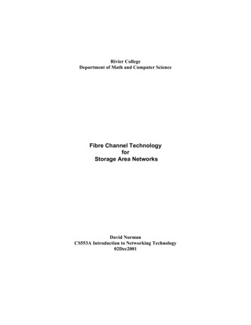
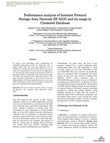
Chapter 1. Introduction to Storage Area NetworkingThis chapter describes in general terms the benefits, the challenges, and risks of using aStorage Area Network (SAN).OverviewThe term SAN designates a new type of storage architecture in which the storage systemsare attached to a high speed network dedicated exclusively to storage. It involves a wholenew network totally distinct from existing communication networks, as is illustrated inFigure1. The application servers (usually UNIX or Windows NT based) access the storageresource through the SAN. Most of the local storage resources are off–loaded from theapplications servers, are managed separately from them, and are consolidated at the datacentre, site, or enterprise level.The SAN architecture is represented below:Figure 1. SAN architectureIn this document, the term SAN refers both to the high speed network infrastructure and thewhole storage architecture, including servers, storage subsystems and managementsoftware.Fibre Channel is currently the preferred technology for implementing SAN architecture. Thetechnology is open, widely accepted, and is defined by ANSI standards. To simplify themigration and integration of legacy equipment, SAN infrastructure based on Fibre Channeltechnology supports multiple protocols. For example, the infrastructure can convey SCSIprotocols, widely used in UNIX and Intel based servers, ESCON for IBM mainframes, and IPto offer networking capability. But the purpose of SAN is not to replace LANs. All theseprotocols can simultaneously use the same cables.This new storage architecture is very different from traditional architectures, where eachstorage system is connected to a single or sometimes to a limited group of servers. That isIntroduction1-1
why they are sometimes called private storage architectures. SAN creates a revolutionsimilar to the one created by LAN deployment in the last decade. SAN is a powerful solutionthat enables data storage management of an unprecedented efficiency and flexibility.The benefits of a SAN are:Cost reduction:The cost of storage systems depends on the cost of the disks, thecost of the enclosure, and the cost of management software. In aprivate storage architecture, it is usually necessary to buy manysmall or medium size enclosures.With SAN architecture, it is possible to reduce the number ofenclosures by storage sharing through the network. Also, diskspace in the enclosures can be shared.Another factor in cost reduction is the performance of thehigh–speed network, which allows the use of larger storagesystems that are usually less expensive (per Gb) than severalsmaller systems.Easyadministration:The separation of servers and storage resources enables thestorage systems and their management applications to becentralized, consolidated, and homogenized.Storage administrators do not need to be trained for serveroperating systems and management software. Management issimplified (less variety and number of equipment, less tools, lessconsoles), and consolidated (aggregation of information fromseveral storage systems).Failure detection and prevention, and trend analysis is mucheasier, because of the lower number of systems to be monitored.High security andavailability:SAN improves the availability and security of the storage. SANoffers a meshed infrastructure with multiple paths. Redundantinterfaces for servers and storage systems provide highly availabledata paths between servers and storage. Because of networkedaccess, the storage remains available even in the case of serverfailure. The cost reduction achieved by storage concentrationjustifies the deployment of RAID solutions, which can be used byany server.The systems themselves can be more secure, with internal highavailability features (hot plug, redundancy). The reduced numberof storage systems to manage facilitates backup operations.Disaster Recovery solutions also increase the availability andsecurity by monitoring master and distant backup sites.ImprovedSAN improves the performance in various ways:performance: any application server can be connected directly to the storagesystems at (multi–)gigabit speed. Compared to today’s networkstorage solutions, based on protocols operating on LANs (NFS,DFS, and SMB), data access is greatly improved data can be shared between hosts, eliminating multiple copies performance is boosted by the use of high–end storage systemswith a high internal bandwidth, larger read and write caches,and efficient processing engines.1-2SAN Installation & Configuration Guide
Quick evolutioncapability:The storage concentration enables very quick adaptation to theevolution of information processing. The storage allocation isextremely flexible and scaleable. You can migrate applicationsfrom server to server, add or remove servers without any impacton the data: no need to move data from one storage system toanother, no need to add disks. The data remains at its location,only routing and access rights need to be modified. Administratorscan add storage without stopping application servers.Challenges and RisksDesigning a SAN is like designing a LAN: it is a network, and the design must integrateanalysis of traffic requirements, the number and location of devices to be connected,topology constraints, and other network related factors. The design must also take intoaccount the availability constraints, which are much higher for a SAN than for legacy LANs.Without redundant SAN architecture, failure of a Fibre Channel (FC) component may stoptens of applications servers, resulting in no access to their data.It is necessary to understand the behaviour of infrastructure equipment such as hubs,switches, bridges, and all the proprietary features implemented by hardware vendors tosimplify interoperability, improve reliability, and manage the infrastructure. This knowledgemust be combined with a good understanding of all the proprietary fail–over solutionssupported by each server, disk array, tape library, SAN infrastructure device andmanagement software.FC technology is not yet mature enough to guarantee interoperability between any deviceas does LAN technology. Thus, the design must take into account the qualified links, orcertified interoperability, published by all SAN vendors, including Bull.The last risk is that much equipment and software (like operating systems for servers) havenot yet integrated the SAN dimension. They still behave like private SCSI storage, trying todiscover all the storage resources, or writing to disks when they recognise an OScompatible format. Sharing storage resources in a heterogeneous server environment mustbe carefully analyzed and managed.SAN managementSAN management covers aspects not covered by previous storage management tools: SAN infrastructure (hubs, switches, bridges) resource sharing.Managing SAN infrastructure is similar to managing a LAN. It entails managing the hubs,switches, bridges, and any other devices in the network infrastructure, analysing thetopology, the status of links, managing virtual networks (using zoning), and monitoring dataflow, performance metrics, QoS, and availability. The product offering is still not complete,due to the immaturity of the technology, to the lack of standards, and to the small size ofhardware vendors of SAN infrastructure. No single vendor provides a completely integratedand dedicated solution that includes all the necessary devices plus applications coveringthose devices.Managing resource sharing is also critical to safe operation in SAN environments. SANenables each server to access each tape drive or each disk logical volume attached to theSAN. It is very flexible, but very complex for the administrators of the servers, because theymay have to manage hundreds of resources, duplicated on all the applications servers. Thatis why it is critical, even in a small SAN (less than 8 servers), to deploy management tools tocontrol resource sharing. Again, there is not yet a dedicated solution. Tape drive allocationand sharing is usually managed by the backup software, which must integrate specific SANfeatures. For the disk resources, LUN access control technology can be used at eitherserver, or disk array level. Zoning can also be used to create virtual networks that simplifymanagement.Introduction1-3
1-4SAN Installation & Configuration Guide
Chapter 2. SAN InfrastructureThis chapter discusses the concepts and technologies applied in SAN infrastructure.FC is the only technology available on the market that allows SANs to be deployed with ahigh level of performance. It is a highly reliable, gigabit interconnection technology thatallows concurrent communications between servers, data storage systems, and otherperipherals using SCSI and IP protocols. One of the advantages of FC technology is thehigh flexibility of the network design: the use of switches and hubs enables you to createlarge infrastructures with a high level of performance and interconnection of variousequipment.Media speedFC operates at various frequencies. The current de–facto standard is 100 MB/s, full–duplex,per physical connection. Equipments operating at 200 MB/s (2 Gbit/s) are available now.100 MB/s and 200 MG/s equipments can be mixed on the same SAN, but only 200 MB/scapable equipments directly connected one to each other will operate at 200 MB/s. But it isnot the ultimate evolution of this technology: products operating higher speed are emerging.The 400 MB/s speed is standardized, but no product is available today.CablingThe FC standards define several media. The most frequently used solutions and theircharacteristics are described in the next table.MediaMaximum cable length62.5 µm multi–mode optical fiber9 µm single mode optical fibercopper175 m10 km30 m (active interface)3–15 m (passive interface)500 m300 m (2 Gbit/s)50 µm multi–mode optical fiber50 µm multi–mode optical fiberTypicalconnectorSCST, SCDB9,HSSDCSCLCCablestructure2 fibers2 fibers4 wires2 fibers2 fibers 50 µm multi–mode optical fibers is the preferred cable for FC. When used at 2GBit/s, thelenght is limited to 300 m. 62.5 µm has been introduced to re–use LAN cabling, where this type of fiber is widelyused. Single mode fibers are reserved for specific applications, such as long distanceinterconnection for site interconnection and/or disaster recovery solutions. Using morepowerful lasers and/or more sensitive receivers, this type of cabling enables connectionsover greater distances than the 10 km defined by the standard. Copper cabling has been widely used due to its lower cost. It is now less and less used,because the price of optical equipment has rapidly decreased, and because of thesensitiveness of the copper technology to EMI, ESD and ground problems. The coppercables are specific to FC technology, and are not compatible with UTP or STP cablesused in LANs, nor with the copper cables used in telco.SAN Infrastructure2-1
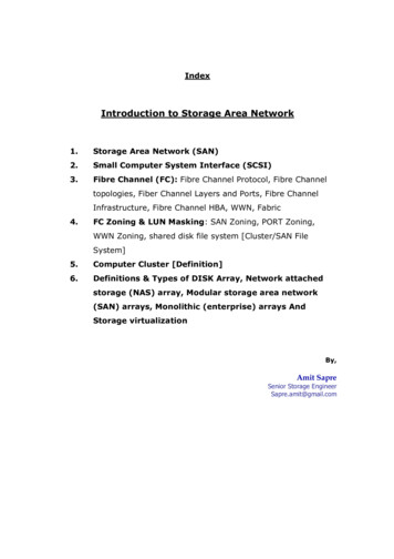
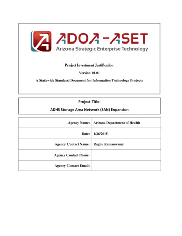
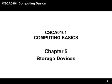
FC NetworksFC networks are implemented in conformance with the ANSI standards, and use somespecific network equipment.Point–to–point connectionThe point–to–point connection between two devices is the simplest cabling solution. Thecable types and distance limitations are described in Cabling, on page 2-1.Figure 2. Point–to point cablingLoops and hubsThe loop has been very popular since the beginning of FC networking. It enablesinterconnection of up to 126 devices at very low cost. The principle of this topology is to linkthe transmitter of each port to the receiver of the next one, thus creating a loop. The loopprotocol is defined by the FC–AL standard.Figure 3. Loop cablingThe loop has several main drawbacks: The bandwidth is shared by the connected devices and only two devices cancommunicate simultaneously. Each device in the loop is a potential point of failure: if the device fails, the loop is brokenand none of the connected devices can communicate. Inserting or removing devices causes loop disruption. No hub equipments at 200 MB/s are available yet. Connectivity is limited to 126 devices.2-2SAN Installation & Configuration Guide
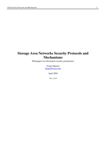
The bandwidth and connectivity limitations are inherent in the protocol used. The risk of loopdisruption is addressed by using FC hubs, which implement a loop within the device inconjunction with bypass circuits for each hub’s port. The bypass circuits maintain the loopintegrity in the case of unused ports or faulty external devices. They also simplify thecabling, converting loop cabling to a star cabling, as illustrated below.Bypass circuitsInactive portbypassedInactive portbypassedHub’s internal loopFigure 4. Star cablingIn practice, a hub may contain one or more logical loops. The distribution of ports in severalloops is performed either with hardware switches that control loop continuity or loopback, orthrough software configuration.Fabrics and switchesA fabric is a network where, contrary to loops, several pairs of devices can communicatesimultaneously, and can use the whole bandwidth. The FC fabric can be compared to otherswitched networks, like Ethernet, ATM or frame relay networks. Each switch’s port analysesthe frame headers, selects the destination port, and puts the frame in the appropriatetransmission queue. Non–blocking designs and advanced forwarding algorithms allow avery low latency (a few micro–seconds), and a full bandwidth per port, regardless ofeffective traffic conditions. The fabric and switch protocols are defined by the FCP, FC–AL,FC–FLA, FC–PLDA standards.The advantage of switches versus hubs are: switches enable the deployment of large networks, switches offer higher performances and scalability (no bandwidth sharing, selection of thebest path), switches provide better fault isolation, switches and fabrics are more stable than loops (less reconfigurations and trafficinterruptions), they have a built–in management function.The disadvantage is usually a higher price per port.SAN Infrastructure2-3
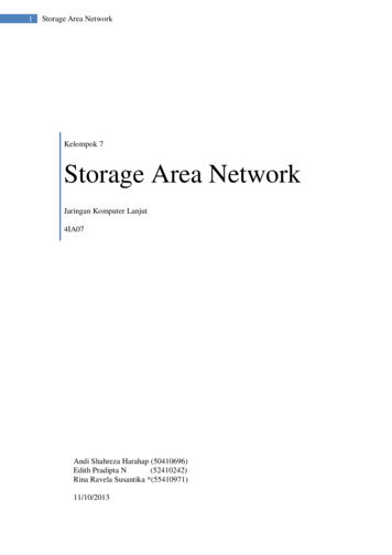
The smallest FC fabric consists of a single switch. Larger fabrics can be interconnected bycascading switches. The protocol permits the connection of millions of devices.conceptual cablingschematic cablingFigure 5. Fabrics and switches cablingIntegrated routing algorithms automatically route circuits and frames across the fabric,through the best path. Resilient multi–switch fabrics can be deployed, with automatic datarouting and re–routing, self–healing and almost unlimited scalability.Figure 6. Switches: automatic data routing2-4SAN Installation & Configuration Guide
Multiple inter–switch links can be aggregated, to avoid the risk of a bandwidth bottleneckwhich may arise when using a single link operating at the same speed as the switch ports.Figure 7. Switches: bandwidthThe speed of the links could be either 100 MB/s or 200 MB/s depending on each equip
Chapter 1. Introduction to Storage Area Networking This chapter describes in general terms the benefits, the challenges, and risks of using a Storage Area Network (SAN). Overview The term SAN designates a new type of storage architecture in which the storage systems are attached to a high speed network dedicated exclusively to storage. It .