Transcription
MOTORTRONICSSolid State AC Motor ControlRX SeriesDigitalMotor Protection Relay5 – 2000AQuick StartReference GuideDocument 022F0701QS - Rev 1
RX Series Digital Motor Protection RelayQuick Start Reference GuidePlease read and understand this Quick Start Reference Guide completely before working with theMotortronics RX Series motor protection relay.General DescriptionThe RX Series is a digitally programmable solid-state motor protection relay packed full of usefulfeatures needed to fully protect your motor and load. Designed to be versatile, it can be used withany configuration of 3 phase motor controller, including Across the Line (DOL), Reversing, 2speed, electro-mechanical Reduced Voltage, Wye-Delta (Star-Delta) and Solid State Softstarters. The RX Series has an integral programming keypad to provide a simple and easymeans of setting its starting and protection features, plus it has easy to understand diagnosticLEDs built into the keypad system. Built-in Metering features can reduce the amount of separatecomponents necessary for complete motor monitoring. The RX Series can accept control powerfrom between 85 & 265VAC without the need to adjust the device and can use a dry contact inputfor Start / Stop control. Line voltage up to 600V can be directly connected to the device, or PTscan be used for up to 15kV motors. Current can be directly monitored up to 75A, or up to 1200Athrough the use of external CTs.Sizes and RatingsThe Motortronics RX Series protection relays are rated by their current capability. Maximum Ampratings are for continuous duty and must not be exceeded. Always check the motor nameplateFLA and Service Factor to ensure proper sizing. Each size of the RX Series has an adjustablerange of current from 50% to 100% of the unit maximum ampere rating. Motors with an FLAsmaller than the lowest setting can be accommodated by using more than one Primary Turnthrough the CT sensing windows (see section 4.1.2 of the Installation & Operation Manual foradditional details).ModelNumberRX-5-PRX-40-PRX-75-PCurrent Range(Direct Reading)Min. - Max.2.5 - 520 -4038 - 75CurrentTable 1:RangeSizes & Ratings(Using Primary Turns)Min. - Max.1 - 2.5 (5 turns max.)10 - 20 (4 turns max.)---Receiving and Unpacking Upon receipt of the product, you should immediately do the following:Carefully unpack the unit from the shipping carton and inspect it for shipping damage (ifdamaged, notify the freight carrier and file a claim within 15 days of receipt).Verify that the model number on the unit matches your purchase order.Confirm that the ratings sticker on the unit matches or is greater than the motor’s HP andcurrent rating.Initial Unit Inspection Make a complete visual check of the unit for damage that may have occurred during shippingand handling. Do not attempt to continue installation or start up the unit if it is damaged.Check for loose mechanical assemblies or broken wires which may have occurred duringtransportation or handling. Loose electrical connections will increase resistance and causethe unit to function improperly.Prior to beginning the installation, verify that the motor and RX Series unit are sized for therated system amperage and voltage.2
Operating PrecautionsCautionDanger Two-wire control systems may restartwithout warning when Auto Reset of theoverload protection is selected. Extremecaution should be exercised. To preventautomatic restarting with 2-wire controlsystems, use external interlocking toprovide sufficient warning and safety tooperators. A Warning Label similar to thatshown below (and the one provided in thepacket with this manual) must be locatedwhere visible (on the starter enclosureand/or the driven equipment) as requiredby local code.When setpoints F044 through F046 areused with two-wire control, the starter mayre-start automatically when the timer hasexpired. Adequate warnings similar tothose in Section 3.1.3.b of the Installation& Operation Manual should be observed. DO NOT disable Overload Protectionunless another Thermal OverloadProtection device exists in the circuit forthe protection of all three phases. Runninga motor without Overload Protectionpresents serious risk of motor damage orfire. THIS PRODUCT IS NOT TO BE USEDAS A GROUND FAULT SAFETY DEVICETO PROTECT PERSONNEL!This feature is only intended to provide alevel of equipment protection againstdamaging ground currents. Ground faultsare potentially dangerous conditions andmust be corrected immediately for safetyof operating personnel. MOTOR FLA (F001)must be programmedfor unit to operate!Do not service equipment with voltageapplied! The unit can be the source of fatalelectrical shocks! To avoid shock hazard,disconnect main and control power beforeworking on the unit. Warning labels mustbe attached to terminals, enclosure andcontrol panel to meet local codes. UseLock Out tags such as the one shownwhen servicing equipment.3 All RX Series relays are shipped from thefactory with F001 set to a default value of0000. If F001 is left at the factory defaultvalue, the unit will not operate. If the userattempts to start the RX Series withoutentering the motor nameplate FLA, therelay will Fault and the display will read“nFLA” (no Full Load Amps). Regarding rotation sensing, there areseveral power utilities that, although theyclaim to provide A-B-C rotation, are actuallyusing B-A-C rotation as defined by mayrotation detection circuits such as that usedby the RX Series relay (example, PacificGas and Electric in California). This onlymeans that at initial startup, you may get aROT trip indication even though you maybelieve you have hooked it up correctly.Simply ensure that your motor is rotatingcorrectly, then set the RX Series to monitorfor any CHANGE in expected rotation fromthat point on. Testing of the output relays may result inunwanted operation. Ensure that controlcircuits are disabled prior to testing therelay functions. Clearing the Thermal Register to allowrestarting without proper cool-down timeafter an Overload Trip will risk motordamage and fire. Use only whereemergency restart is necessary withknowledge of these potential hazards.
Location & MountingChoosing a Location Proper location of the RX Series is necessary to achieve specified performance and normaloperation lifetime. The device should always be installed in an area where the followingconditions exist:Ambient operating temperature:Panel (open chassis) unit: 0 to 50 C (32 to 122 F)Enclosed unit: 0 to 40 C (32 to 104 F)Protected from rain, moisture and direct sun.Humidity: 5 to 95% non-condensingFree from metallic particles, conductive dust and corrosive gasFree from excessive vibration (below 0.5G)Units must be mounted in the appropriate type of enclosure.ClearancesMake sure there is sufficient clearance all around the unit for cooling, wiring and maintenancepurposes. The RX Series was designed for close clearances, but a minimum clearance of 1”(25 mm) on all sides is necessary to provide for effective airflow and cooling.Othe r De v ice s,i.e . M otor Starter1" minimum (25 mm)RX SeriesRelay1" minimum (25 mm)Figure 1: Minimum Spacing Requirements for the RX SeriesMounting the RX Series The RX Series is designed to snap onto a standard duty DIN rail, or to mount directly to apanel with #8 screws (4mm).When drilling or punching holes in an enclosure containing an RX Series relay, cover theelectrical assembly to prevent metal filings from becoming lodged in areas which can causeclearance reduction or actually short out electronics. After mounting work has beencompleted, thoroughly clean & vacuum the area, then re-inspect the unit for possible intrusionof foreign material.4
Remote Keypad MountingThe keypad / operator interface unit can be remotely mounted up to 6’ (1.8 meters) away from therelay, i.e. on the enclosure door. A remote mounting kit is not necessary, only a keypad sealgasket is needed (this is only required for NEMA 12 / IP65 enclosures) and a standard DB-9connection cable (computer serial cable). If desired, the end-user can make this cable usingstandard DB-9 connectors, Male for the keypad, Female for the base unit. The keypad can bemounted using 4 small #6 (M3) screws (customer supplied) and by drilling a 7/8” (22mm) hole toaccommodate the DB-9 connector that is located beneath the keypad assembly.DB-9 CableUp To 6 Feet (1.8m)DB-9 SocketDB-9MDB-9FFigure 2: Keypad Rear Viewfor Remote MountingRX Relay BaseFigure 3: Remote KeypadMounting Kit ComponentsTerminationsAll line and control power terminations are to be made to the plated saddle clamp terminalslocated on each unit. Motortronics recommends using crimp-on terminals wherever practical.Motor current conductors can feed through the built-in CT holes in the base of the relay.The RX-5-P also comes with a Line-Load Power Terminal block that permits separate Lineand Load power connections to be made with up-to 12ga wire. This unit can be removed toprovide access to the feed-through CT holes if desired.Note: All wiring must be sized according to local code standards.Terminal connections on the RX Series relay are divided into 2 groups. With the unit orientedhorizontally, TB1 for control connections is a 7-point terminal block located across the bottomand TB2 for power connections is a 5-point terminal block located across the top.TB2Figure 4: RX SeriesRelay BaseConnectionTerminalsTB15
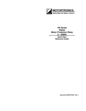
Control ConnectionsFollowing are descriptions of control connection points. There are two output relays relating toTB2, each with its own power ratings. Relay 1 is designed for higher power operation, 10A240VAC resistive or inductive and carries a 1/3HP rating at 120VAC (max. 10.0 LRA). Relay 2 israted 5A 240VAC resistive, 1200VA maximum and is not rated for direct switching of motors.Both relays must be protected from currents in excess of their ratings, either with a fuse or withother suitable current protection devices. See 4.2.4 of the Installation & Programming Manual formore details.RELAY 1NO COMFigure 5: ControlConnections - TB1RELAY 2NC COMNOMax. 10A 240VAC1/3HP (250W)Inductive LoadISOINPUTMax. 5A 240VAC1200VATwo Wire Isolated Input / PLC ConnectionAn optional Isolated Input is provided that can be used with a dry contact, for example from aseparate contact on a switch, relay or relay output of a PLC. This input can be programmed aseither a Start / Run command for use in conjunction with the Process Timer and/or Time ClockController functions, or as a Remote Start when using serial communications control. It can alsobe programmed as an External Trip function. See F063 in section 5.6.11 of the Operation andProgramming Manual for additional information.RX Programming:"External Trip"RELAY 1NO COMNORELAY 2NC COMRX Programming:"Start / Run"RELAY 1NO COMISOINPUTNORELAY 2NC COMISOINPUTFigure 7: Start / RunCommand – TB1Figure 6: External InputWiring - TB1PLCRunHigh Pressure AlarmCloses on Pressure RiseAC Power ConnectionsSeparate AC Control Power supply is required to power the electronics of the RX Series relay.Control power can be anywhere from 85 to 265VAC, either 50 or 60 Hz and must be connected tothe terminals marked “AC IN 120/240VAC” of TB-2. These terminals are the equivalent of A1 andA2 in IEC terminology, as shown in figure 4 below. This control voltage input must be supplied bythe customer.AC ControlPower Supply80 - 265VAC, 50/60 HzFigure 8: Control PowerSupply Connections - TB2L1L2L3(A1)( A2)Not Polarity Sensitive6
Line Voltage Detection ConnectionsConnect appropriately sized power conductors to the base unit input terminals marked L1, L2, L3(R, S, T for IEC users) underneath the keypad. These will be for Line Voltage Detection, not forthe motor load (see below), but should be fuse protected for 5A max. Avoid routing any powerwires over the display.3-Phase VoltageLevel DetectionFigure 9: Line VoltageDetection Connections - TB2L2(A1)L3( A2)Motor Power ConnectionsMotor power connections differ on different sizes. On the RX-5-P, the user has 2 choices;Separate Line and Load connections are made to terminals on the relay base, or Feed-Throughwiring.Use the Separate Line and Load connections when the motor is small enough ( 5A FLA) to beconnected directly to the terminal block screws on the ntrollerFigure 10: Separate Line &Load connectionsOn the RX-40-P and RX-75-P, the user can just pass the motor lead connections through theinternal CTs of the RX Series relay base without making connection directly to the relay. This canalso be done with the RX-5-P by removing the connection akerMTRFigure 11: Feed ThroughWiringMotorController7
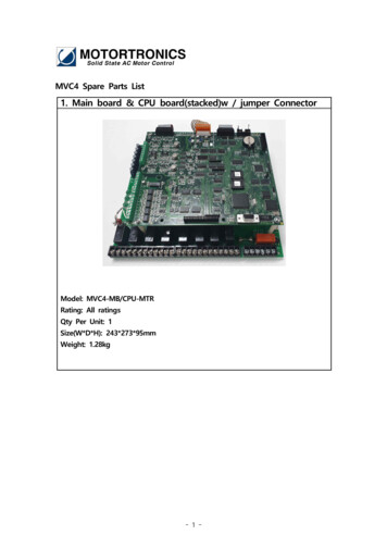
Large Motor ConnectionsThe RX-5 is also used for large motors where external CTs are necessary to step the motorcurrent down to 5A. Simply pass the motor leads through the external CT windows, then connectthe CT secondary conductors to the RX-5 terminal adaptor (or pass them through the internal CTwindows). You must also reprogram Function F073 for the external CT ratio in order to make theRX aware of the higher motor currents.MCDisconOrCircuitBreakerFigure 12: ConnectingExternal CTsMTRExternalMotorControllerCTs5AUsing Primary Turns to Increase RangeThe RX relay can be used to read motor currents lower than thestandard rating of the unit by increasing the current read by the CTsthrough the use of “Primary Turns”. Each “turn” refers to the fact thatthe power conductor is passing through the CT core. 2 passesthrough the core is referred to as 2 Primary Turns, also meaning thatthe current read by the CT is increased 2 times (2x). 4 PrimaryTurns would then mean that the motor conductors pass through theCTs 4 times and the current read is 4x the CT current. Another wayto look at it is that the relay range has been divided by the number ofturns. For example, if the motor FLA is between 5A (upper limit ofthe RX-5) and 20A (lower limit of the RX-40), use the RX-40 andpass the current through the built-in CT windows for more turns. Forloads from 5 -10A, make a loop to pass the motor leads through 4times (4 “turns”). The maximum amperage rating is now 40 4 or10A, so the range is 5 – 10A. For loads 10 – 20A, use 2 PrimaryTurns through the windows for a rating of 40 2 or 20A, so a newrange of 10-20A. This doubles or quadruples the range of the relay,but must be coordinated by programming the correctFigure 13: Example of 2number of turns into F074 (see section 5.6.12.a of thePrimary Turns Through anInstallation and Programming Manual for programming details).Internal CTIn general when using external CTs, it is always best to choose aCT ratio that works out to have your motor FLA fall within the range of adjustment of the RX relay.Primary Turns can also be used with external CTs on the RX-5 to increase the range of the RXrelay for motors where the FLA falls outside of its settings. For instance, if a motor has 240FLA,and you must use an external CT rated 500:5, the 5A CT current will represent a maximum of500A, but the relay can only be turned down to 2.5A, so the lowest adjustment would be 250A,above the motor FLA. To achieve proper protection, pass the 5A CT current through the relay CTwindows twice (2 turns). The 5A external CT current now represents 250A, so the range ofadjustment becomes 120 – 250A, which properly covers the motor nameplate FLA. Remember toalways program the External CT ratio into Function F073, as well as the Primary Turns into F074.This allows your display and protection settings to accurately represent the actual motor powerreadings. See section 5.6.12.a of the Installation & Programming Manual for programming details.8
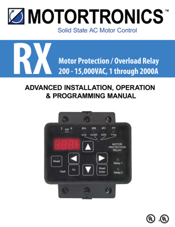
ProgrammingDisplay ModesThere are three modes of display: the Program Mode, the Status Display Mode, and the FaultMode.Program ModeThe relay must first be in Stop Mode in order to enter the Program Mode.Use the Program Mode to view or change Function (Fn) settings. To enter the Program Mode,press the [Fn] key once from the Status Screen described in 5.3.1 of the Installation &Programming Manual. The first time you enter the Program Mode after power has been cycled tothe relay, the initial function [F001] should display with the selected digit flashing. If the RXSeries relay has been programmed and power to the unit has not been cycled, the readout willdisplay the last function viewed or changed. To change to a different function, use the arrow keys.Figure 14: Operator InterfaceViewing Function Programming and ValuesThe programming of each individual Function can be viewed without making changes (values canalso be viewed in the Run Mode, however no changes can be made). Each Function is signifiedby the letter “F” at the beginning of the data, the 4 digit value of the function follows after hittingthe [READ/ENTER] key. [F001] The “F” indicates the programmable Function. [0000] This is the present setting of the applicable function. This display may includedecimals between digits depending on the function setting’s range and incremental steps.Viewing a Function’s Set Value: Motor FLA Setting[0000]Indicates that Phase A is drawing nocurrent(unit is in Off mode).Press the Fn key[F001] Indicates that this is Function 001(Motor FLA).Press Read / Enter keyto view the F001’s value[0360] Indicates that the programmed motorFLA is 360 Amps.Press the Fn keyto return to the function[F001] Indicates that you have returned to theFunction Select screen.Press the Fn key again to return to the StatusDisplay Mode[0000] Default screen.9Figure 15: Programmed Values Display
Note:If password protection has been enabled, operator will need to obtain password accessbefore function settings can be changed. See Section 5.6.12 and Appendix A of theInstallation & Operation Manual.Enabling Password Protection / Parameter LockThe RX Series relay is shipped with the Level 1 password protection disabled (F070 0). If itbecomes necessary to prevent these parameters from being changed inadvertently, set thepassword in function F070. See section 5.6.12 and Appendix A of the Installation & ProgrammingManual for details. If the display reads [Loc] when the [READ/ENTER] key is pressed, theparameter lock is enabled.Note: functions F071 through F108 are password protected by F072 and this is shipped with thepassword ENABLED. Contact the factory for access to these functions.It is best to operate the motor at its full load starting conditions to achieve the proper time, torqueand ramp settings. Initial factory settings are set to accommodate general motor applications andprovide basic motor protection. Advanced features must be enabled via programming. The onlyparameter that MUST be set by the user is motor FLA (F001).ResetFnRead/EnterKeysUp andDownArrowsRight andLeftArrowsTripRelay 1and 2I and ELEDsPhaseA, B and CPF(Lower)kVAR,kVAR,kWH, Freq.Display8888.Clears the Trip indication and releases the Trip Relay.Enters or exits the Program Mode.Used to Read a value of either a Function or its contents. After changes are made,pressing it again “Enters” the changes in to the relay EEPROM memory (stores).Navigates through the Status Display Mode, scrolls up and down through the FunctionList, increases or decreases the value of the active (flashing) digit and scrolls throughthe fault history. When entering values, holding the key down for more than 2 secondswill activate Auto-step, which increases it’s rate the longer the key is held down.Each key press shifts the active (flashing) digit to the right or left by one position,allowing you to change higher values of functions without waiting to Auto-step thoughlarge numbers.Lights whenever any Trip function is active, stays lit as long as the relay is in Trip Mode(see below).Lights when the respective relay is energized“I” LED indicates the value of the display is based on Current. “E” LED indicates thevalue in the display is based on Voltage. If both are lit simultaneously, the displayedvalue is kW (motor power)Indicates that the displayed value is based on the phase(s) shown. If all 3 are On, thisindicates the value shown is an Average of all 3 phases.Indicates that the displayed value is Motor Power FactorLights to indicate that the Phase LEDs described above are indicating the status isbased on the descriptions shown below the LEDs instead of above. So the A, B, C andPF LEDs become kVA, kVAR, kWH and Frequency respectively.ND2 Tier indicating that the displayed value is one of these power conditions (instead ofPhase Currents and Power Factor).4 digit 7 segment display with a decimal point on the right side indicating Phase A.Table 2: Display Features10
Status Display Mode (Default Display)The Status Display Mode displays 20 “screens” of information as shown in the chart below. Thisis the default mode when the RX Series relay is first powered on and also the point from wherethe Program Mode can be entered. Although all 20 screens can be scrolled through, the firstscreen (default screen) can be programmed in F076, see section 5.6.12.b of the Installation &Programming Manual for additional details.ActionScroll ThroughDisplaysDefault Current in Phase AU keyCurrent in Phase BU keyCurrent in Phase CU keyAverage CurrentU keyCurrent Imbalance %U keyVoltage ABDisplay Example047704800483048000010 2 3 0 if V 99990 2 . 3 6 if V 9999LED'sLED'sSteadyBlinkingI ØAI ØBI ØCI ØA, ØB, ØCIØA, ØB, ØCE ØA, ØBDecimal point is added tothe center if Voltageexceeds 9999V, indicatingthe content value is kV(indicating kV or 2360V).U keyVoltage BCU keyVoltage CAU keyAverage VoltageU keyVoltage Imbalance %U keyPower FactorU keyMotor power (kW)0228023302300002L 0.85 , or1.031 0 0 0 , ifRemarksE ØB, ØCE ØA, ØCE ØA, ØB, ØCEØA, ØB, ØCL: Inductive Load (lagging): Capacitive Load(leading)LLPF(kW) 9999U keykVAU keykVARU keyEnergy use in kWhU keyFrequencyU keyGround CurrentU keyProcess TimerRemaining TimeTime Clock ControllerTime (24hr format)Remaining MotorThermal CapacityU keyU keyU key0 0 0 1.(kW) 9999(indicating MW).Similar to above, exceptkVASimilar to above, exceptkVARSimilar to above, exceptkWhØA Row2ØB Row2ØC Row2060.0G0020014Decimal point is added tothe right if the displayedvalue is greater than 9999,which indicates the contentvalue is MW (or MVA,MVAR, MWh as the casemay be).I EifPF Row2Left digit is always 0Display(minutes)DecimalPoint01.20H100Blinks when process timeis counting down.Blinks after start input isclosed.“H” can be thought oh asmotor “Heat” capacityScrolls back to beginningTable 3: Status DisplaysEnabling Password Protection / Parameter LockThe RX Series relay is shipped with the Level 1 password protection disabled (F070 0). If itbecomes necessary to prevent these parameters from being changed inadvertently, set thepassword in function F070. See section 5.6.12 and Appendix A for details. If the display reads [Loc]when the [READ/ENTER] key is pressed, the parameter lock is enabled.Because they involve safety issues, functions F071 through F108 are password protected by F072and this is shipped with the password ENABLED. Contact the factory for access to these functions.11
Changing a Function’s Set ValueFrom the instructions on the previous page, after hitting the [READ/ENTER] key the display willshow the value of that function with one digit flashing (usually the rightmost digit). Flashingindicates this is the digit to be altered (similar to cursor position). Use the UP arrow key toincrement the value of the flashing digit. Use the DOWN arrow key to decrement the value of theflashing digit. Use the LEFT or RIGHT arrow to select the next digit to be altered. Values can onlybe changed within the Adjustment Range of the function parameter.Viewing a Function’s Set Value[0000] Indicates Phase A is drawing nocurrent(unit is in Off mode).Press the [Fn] key[F001] Indicates this is Function 001(Motor FLA).Press [READ/ENTER] keyto view the F001 value[0048] Indicates the programmed motorFLA is 48 Amps. The farthest leftdigit (8) is flashing, indicating thatthis is the digit that you will alter(cursor position).Press the UP Arrow keyto increase this digit value[0049] Indicates you have increased theleft digit to a value of 9.Press the LEFT Arrow keyto shift left to the next digit[0049] The second digit from the left isnow flashing, indicating a newcursor position.Press the UP Arrow keyto increase this digit value[0059] Indicates you have increased the2nd to left digit to a value of 5 (10’splace).Figure 16: Programmed Values DisplayPress [READ/ENTER] keyto store the new value[End] The word “End” will flash briefly to indicate that the new value has been entered andaccepted. After flashing once, the display will revert to showing the Functionnumber.Storing the Altered Value of a FunctionOnce the desired value is displayed, press the [READ/ENTER] key. This stores the value inmemory. The readout momentarily displays [End] and then returns to the function code.Caution!If the Fn key is pressed or power is lost before the [READ/ENTER] key is pressed, the RXSeries Relay will not store the selected value in memory.12
Programming Function ListMotor and Line SettingsFn #GroupFunction DescriptionMotor Nameplate FLAF001FLA must be programmedfor relay to function.Adjustment / Display RangeSettingIncrementsFactorySetting1 – 2000A, adjustable between50-100% of Max Amp Rating.Upper limit of range automaticallyadjusts downward as Service factoris increased.1 amp00.051.0 SF1.00 - 1.30 SFOverload Class During StartNEMA / UL Class 5 - 205Class 10Overload Class During RunNEMA / UL Class 5 - 305Class 10Overload Reset0 Manual1 Auto2 Disabled Overload10(Manual)Voltage Input (nominal Line)200 – 600 volt1480F007kV Voltage Input (nominalline, Medium Voltage).60 – 15kV.014.16F008Line Frequency50 or 60 Hz-60F009Acceleration TimeF003F004F005F006Motor and Overload Info.Motor NameplateService FactorF002Table 4: Motor0-300 seconds [0 Disabled]ManualSection5.6.1 and3.2and OverloadFunctionGroup130Current and Ground Fault SettingsFn #GroupFunction DescriptionAdjustment / Display RangeCurrent Imbalance Trip %0, 1 - 30% of FLA [0 Disabled]F011Current Imbalance Trip Delay1 - 20 secondsF012Over Current Trip %0, 50 – 300% of FLA [0 Disabled]Over Current Trip Delay1 - 20 secondsUnder Current %0, 10 – 90% of FLA [0 Disabled]Under Current Trip Delay1 - 60 secondsStall Detection Trip Level0, 100 – 600% of FLA [0 Disabled]Stall Detection Trip Delay1 - 10 secondsPeak Current Trip %0, 800 – 1400% [0 Disabled]Peak Current Trip Delay0, .01 - .5 secondsF020Ground Fault Current TripValue0, 5 – 90% of CT Value [0 Disabled]F021Ground Fault Current TripDelayF013F014F015F016F017F018F019Current and Ground Fault ProtectionF0101 – 60 d)21(%)0111(%)0125(%)01210(%)1000 (%).01.051(%)0ManualSection5.6.212Table 5: Current & Voltage ProtectionFunctionGroup13
Voltage Protection SettingsFn #GroupFunction DescriptionAdjustment / Display RangeVoltage Imbalance Trip %0, 1 – 30% [0 Disabled]F023Voltage Imbalance Trip Delay1 – 20 secondsOver Voltage Trip %0, 1 – 10% [0 Disabled]Over Voltage Trip Delay1 – 20 secondsUnder Voltage Trip on Start %0, 1 – 20% [0 Disabled]UV Trip on Start Delay1 – 180 secondsF028Under Voltage Trip on Run %0, 1 – 20% [0 Disabled]F029UV Trip Delay during Run1 – 20 secondsF024F025F026F027Voltage 1101(%)01101(%)01101(%)0ManualSection5.6.3Table 6: Voltage ProtectionFunctionGroup12Fn #GroupF030Phase and Frequency ProtectionPhase and Frequency Protection SettingsF031F032F033F034F035F036Function DescriptionAdjustment / Display Range0, 1 or 2Phase Rotation Trip0 Disabled, 1 ABC, 2 ACB]SettingIncrementsFactorySetting11Phase Rotation Trip Delay1 – 20 seconds12Phase Loss Trip and Delay0, 1-20 Seconds [0 Disabled]11Over Frequency Trip Limit0, 1 – 10Hz [0 Disabled]10Over Frequency Trip Delay1 – 20 seconds12Under Frequency Trip Limit0, 1 – 10Hz [0 Disabled]10Under Frequency Trip Delay1 – 20 seconds12ManualSection5.6.4Table 7: Phase & Frequency Protection Function GroupMotor Power Protection SettingsFn #GroupFunction DescriptionAdjustment / Display RangeSettingIncrementsFactorySetting101%50(%)Motor KW Trip0-20 Disabled1 Over KW Trip2 Under KW TripMotor KW Trip Point20 – 100% of full load KWMotor KW Trip Delay Time1 – 999 minutes11Power Factor Trip Range0, 1 – 3 [0 Disabled, 1 lag, 2 lead,3 lead/lag]10F041Power Factor Trip Point.01 – 1.01.50F042Power Factor Trip Delay Time1 – 20 seconds12F043Power Factor Current Direction0 - 1, [0 Normal, 1 Reversed]10F038F039F040Power ProtectionF037ManualSection5.6.5Table 8: Power Protection Function Group14
Lockout / Inhibit SettingsF044F045F046GroupLockouts,and InhibitsFn #Function DescriptionAdjustment / Display RangeCoast Down (Back Spin)Lockout Timer0 Disabled, or 1 - 60 minutesMaximum Starts per Hour0 Disabled, or 1 – 10 startsMinimum Time BetweenStarts Inhibit0 Disabled, or 1 - 60 minutesSettingIncrements1 minute11 d0Disabled5.6.6Table 9: Lockouts & Inhibits GroupOutput Relay SettingsFn #GroupFunction DescriptionAdjustment / Display RangeSettingIncrementsFactorySettingF047Aux Relay 1 settingOperation # 1 – 30: see below121F048Aux Relay 2 settingOperation # 1 – 30: see below128ManualSection1 Over Load During Start (OLA)2 Over Load Constant Speed (OLC)3 Any Overload Trip (OLA or OLC)4 Voltage Imbalance (EI)5 Over Voltage (OE)6 Under Voltage During Start (UEA)7 Under Voltage Constant Speed (UEC)8 Phase Rotation (Rt)9 Over Frequency (OF)10 Under Frequency (UF)11 Current Imbalance (CI)Output Relays12 Over Current (OC)13 Stall Detection (Sd)14 Peak Current (PC)15 Under Current (UC)Relay ProgrammingOperation Options:5.6.7and5.6.1716 Ground Fault (GF)17 Power Factor (PF)18 KW Power Trip (Pr)19 Phase Loss (PL)20 External Trip (Et)21 Any Trip22 Coast Down Time (Cdt) Inhibit23 Starts Per Hour (SPH) Inhibit24 Time Between Starts (
High Pressure Alarm Closes on Pressure Rise RX Programming: "External Trip" NO COM NO NC COM INPUT AC Control 80 - 265VAC, 50/60 Hz (A1) ( A2) Not Polarity Sensitive Figure 8: Control Power Supply Connections - TB2 Max. 10A 240VAC 1/3HP (250W) Inductive Load Max. 5A 240VAC 1200VA