Transcription
Hardware Reference GuideHP gt7720/gt7725 Thin Client
Copyright 2008–2009 Hewlett-PackardDevelopment Company, L.P. Theinformation contained herein is subject tochange without notice.Microsoft and Windows are trademarks ofMicrosoft Corporation in the U.S. and othercountries.The only warranties for HP products andservices are set forth in the express warrantystatements accompanying such productsand services. Nothing herein should beconstrued as constituting an additionalwarranty. HP shall not be liable for technicalor editorial errors or omissions containedherein.This document contains proprietaryinformation that is protected by copyright. Nopart of this document may be photocopied,reproduced, or translated to anotherlanguage without the prior written consent ofHewlett-Packard Company.Hardware Reference GuideHP gt7720/gt7725 Thin ClientThird Edition (April 2009)Second Edition (April 2009)First Edition (October 2008)Document Part Number: 510186-003
About This BookWARNING! Text set off in this manner indicates that failure to follow directions could result in bodilyharm or loss of life.CAUTION: Text set off in this manner indicates that failure to follow directions could result in damageto equipment or loss of information.NOTE:ENWWText set off in this manner provides important supplemental information.iii
ivAbout This BookENWW
Table of contents1 Product FeaturesStandard Features . 1Thin Client Management Solutions . 2Front Panel Components . 3Top Components . 3Rear Panel Components . 4Dual-head Configuration . 4Quad-head Configuration . 5Installing the Rubber Feet . 5Installing the Stand . 6Removing the Stand . 6Using the Keyboard . 8Windows Logo Key . 9Additional Function Keys . 9Special Mouse Functions . 9Serial Number Location . 102 Hardware ChangesGeneral Hardware Installation Sequence . 11Removing and Replacing the Secure USB Compartment Cover . 12Removing the Secure USB Compartment Cover . 12Replacing the Secure USB Compartment Cover . 13Removing and Replacing the Side Access Panel, Expansion Module, and Metal Side Cover . 15Removing the Side Access Panel, Expansion Module, and Metal Side Cover . 15Replacing the Metal Side Cover, Expansion Module, and Side Access Panel . 16Installing Thin Client Options . 18Installing the USB Device . 19Removing and Replacing the Battery . 19Installing the PCI-Express Card . 20External Drives . 21Appendix A SpecificationsENWWv
Appendix B Security ProvisionsSecuring the Thin Client . 24Appendix C Mounting the Thin ClientHP Quick Release . 25Supported Mounting Options . 27Non-supported Mounting Option . 29Appendix D Thin Client OperationRoutine Thin Client Care . 30Supported Orientations . 30Non-supported Orientation . 32Appendix E Electrostatic DischargePreventing Electrostatic Damage . 33Grounding Methods . 33Appendix F Shipping InformationShipping Preparation . 34Important Service Repair Information . 34Index . 35viENWW
1Product FeaturesStandard FeaturesThank you for purchasing an HP thin client. We hope you have years of use from our thin clients. Ourgoal is to provide you with award-winning clients that are easy to deploy and manage with the powerand reliability you expect.The next sections describe the features of the thin client. For a complete list of the hardware and softwareinstalled on a specific model, visit http://www.hp.com and search for your specific thin client model.The following features are common to all HP thin clients: no hard drives or diskette drives 5-minute hardware setup time central deployment and management using HP Management SolutionsVarious options are available for your thin client. For more information about available options, visit theHP Web site at http://www.hp.com and search for your specific thin client model.ENWWStandard Features1
Thin Client Management SolutionsHP has a comprehensive suite of management solutions to fit your needs. This allows you to choosesolutions that will work best in your environment.HP ThinState Tools are a set of handy utilities that allow you to copy settings and software images fromone thin client to another using a USB drive key. HP ThinState tools complement other managementsolutions and are included with HP thin client operating systems.HP Device Manager is an enterprise-class thin client management software application that allowscustomers to view their thin client assets remotely and to manipulate those thin clients to meet therequired business need. It is robust, yet easy to install and use. HP Device Manager lets you track,configure, upgrade, clone, and manage thousands of individual devices from a centralized location. HPDevice Manager agents are included in most HP thin clients.HP Client Automation is an industry-leading device management product, which is part of a biggerBusiness Service Automation environment management solution. With HP Client Automation, you canmanage simple thin client deployments or highly complex IT environments that contain a combinationof thin clients, PCs, blades, servers and other common computer-based resources. HP ClientAutomation agents work with all HP thin clients. For more information on HP Client Automation, pleasevisit the HP Web site at http://www.hp.com and search for “Business Service Automation.”HP continues to partner with Altiris to manage HP thin clients. Altiris Deployment Solution is a leadingtool for quick deployment and ongoing management of thin clients in your organization. With your thinclient hardware purchase, you are entitled to a complimentary, current release of Altiris DeploymentSolution. For additional information, refer to the Quick Setup and Getting Started Guide that came withyour thin client, and visit the Altiris Web site at http://www.altiris.com/.2Chapter 1 Product FeaturesENWW
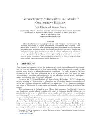
Front Panel ComponentsFigure 1-1 Front panel components(1)Secure USB compartment(5)Power LED(2)Power button(6)Line-out (headphone) audio connector(3)Flash activity LED(7)Universal serial bus (USB) connectors (2)(4)Line-in (microphone) connector* For more information, refer to the model-specific QuickSpecs at kSpecs Archives/QuickSpecs Archives.html.Top ComponentsFor more information, http://www.hp.com and search for your specific thin client model to find the modelspecific QuickSpecs.The secure USB compartment allows you to use two USB devices in a secured location.Figure 1-2 Top components, external viewENWWFront Panel Components3
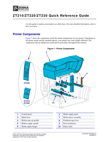
(1)Cable lock slot(2)Secure USB compartmentFigure 1-3 Top components, internal view(1)Cable lock slot(2)Secure USB compartment ports (2)Rear Panel ComponentsFor more information, http://www.hp.com and search for your specific thin client model to find the modelspecific QuickSpecs.Dual-head ConfigurationFigure 1-4 Rear panel components4(1)Line-out (headphone) audio connector(5)DVI-D connector(2)Ethernet RJ-45 connector(6)DVI-I connectorChapter 1 Product FeaturesENWW
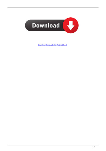
(3)Universal serial bus (USB) connectors (4)(7)Serial connector(4)PS/2 connectors (2)(8)Power connectorQuad-head ConfigurationNOTE:This applies to the HP gt7725 thin client with expansion module.The quad-head configuration is only available with the HP gt7725 thin clientFigure 1-5 Rear panel components(1)DMS-59 connector for DVI-I outputs (2) (splitter cableincluded)(6)PS/2 connectors (2)(2)S-Video out (not supported)(7)DVI-D connector(3)Line-out (headphone) audio connector(8)DVI-I connector(4)Ethernet RJ-45 connector(9)Serial connector(5)Universal serial bus (USB) connectors (4)(10)Power connectorInstalling the Rubber FeetTo install the rubber feet:ENWW1.Locate the holes in the corners of the left side of the thin client.2.Remove the feet from their backing.Installing the Rubber Feet5
3.Align the feet with their holes and press them in securely.Figure 1-6 Installing the rubber feetInstalling the StandTo install the stand:1.Turn unit upside down.2.Locate the slots on the bottom of the unit into which the tabs on the stand fit.3.Insert the tabs into the slots (1), and then slide the stand about 1.26 cm (1/2 inch) toward the backof the unit until it locks into place (2).Figure 1-7 Installing the standRemoving the StandTo remove the stand:1.6Turn unit upside down.Chapter 1 Product FeaturesENWW
2.Press the tab (1), and then slide the stand about 1.26 cm (1/2 inch) toward the front of the unit andlift the stand off the unit (2).Figure 1-8 Removing the standENWWRemoving the Stand7
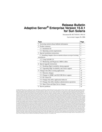
Using the KeyboardFigure 1-9 Keyboard features(1)Caps Lock keyActivates/deactivates the Caps Lock feature.(2)Scroll Lock keyActivates/deactivates the Scroll Lock feature.(3)Num Lock keyActivates/deactivates the Num Lock feature.(4)Ctrl keyUse in combination with another key; its function depends on theapplication software you are using.(5)Windows Logo Key12Opens the Start menu in Microsoft Windows. Use in combination withother keys to perform other functions. For more information, see WindowsLogo Key on page 9.(6)Alt keyUse in combination with another key; its function depends on theapplication software you are using.(7)Application key1Similar to the right mouse button, opens pop-up menus in a MicrosoftOffice application. May perform other functions in other softwareapplications.(8)Editing keysIncludes the following: Insert, Home, Page Up, Delete, End, and PageDown.Hold Ctrl and Alt while pressing Delete to restart the thin client.1Available in select geographic regions.2Applies to XPe thin clients only.8Chapter 1 Product FeaturesENWW
Windows Logo KeyUse the Windows Logo Key in combination with other keys to perform certain functions available inWindows operating systems.Windows Logo Key TabSwitch between open items.Windows Logo Key eOpen My Computer.Windows Logo Key fSearch for a file or folder.Windows Logo Key Ctrl fSearch for computers.Windows Logo Key mMinimize all windows.Windows Logo Key Shift mUndo minimize all.Windows Logo Key BreakDisplay the System Properties dialog box.Windows Logo Key rOpen the Run dialog box.Additional Function KeysThe following key combinations also work on all thin clients regardless of operating system:Alt EscCycles through minimized applications.Alt TabCycles through open applications.Alt Shift TabSwitches to the previous session.Special Mouse FunctionsMost software applications support the use of a mouse. The functions assigned to each mouse buttondepend on the software applications you are using.ENWWSpecial Mouse Functions9
Serial Number LocationEvery thin client includes a unique serial number located as shown in the following illustration. Have thisnumber available when contacting HP customer service for assistance.Figure 1-10 Serial number location10Chapter 1 Product FeaturesENWW
2Hardware ChangesGeneral Hardware Installation SequenceTo ensure the proper installation thin client hardware components:1.Back up any data, if necessary.2.If the thin client is powered on:a.Turn off the computer properly through the operating system, then turn off any externaldevices.b.Disconnect the power cord from the power outlet and disconnect any external devices.c.Disconnect any external devices or cables, such as a cable lock.WARNING! To reduce the risk of personal injury from electrical shock and/or hot surfaces, besure to disconnect the power cord from the wall outlet and allow the internal system componentsto cool before touching.WARNING! To reduce the risk of electrical shock, fire, or damage to the equipment, do not plugtelecommunications or telephone connectors into the network interface controller (NIC)receptacles.CAUTION: Static electricity can damage the electronic components of the thin client or optionalequipment. Before beginning these procedures, ensure that you are discharged of static electricityby briefly touching a grounded metal object. See Electrostatic Discharge on page 33 for moreinformation.ENWW3.Remove the secure USB compartment cover. See Removing and Replacing the Secure USBCompartment Cover on page 12 for more information.4.Remove the side access panel, expansion module, and metal side cover. See Removing andReplacing the Side Access Panel, Expansion Module, and Metal Side Cover on page 15 for moreinformation.5.Remove any hardware that you will replace.6.Install or replace equipment. For removal and replacement procedures, see the followingsections: Installing the USB Device on page 19 Removing and Replacing the Battery on page 19General Hardware Installation Sequence11
Installing the PCI-Express Card on page 20 External Drives on page 21NOTE: Option kits include more detailed installation instructions.7.Replace the metal side cover, expansion module, and side access panel. See Removing andReplacing the Side Access Panel, Expansion Module, and Metal Side Cover on page 15.8.Replace the secure USB compartment cover. See Removing and Replacing the Secure USBCompartment Cover on page 12.9.Reconnect any external devices and power cords.10. Turn on the monitor, the thin client, and any devices you want to test.11. Load any necessary drivers.NOTE: You can download select hardware drivers from HP. Go to http://www.hp.com and searchfor your specific thin client model.12. Reconfigure the thin client, if necessary.Removing and Replacing the Secure USB CompartmentCoverThe secure USB compartment allows you to install two USB devices in a secure location inside the thinclient. Along with providing a hidden location, the secure USB compartment can be locked by theoptional security cable lock.CAUTION: The ambient temperature inside of the secure USB compartment can reach up to 55 C(131 F) in worst case conditions. Make sure the specifications for any device you install in thecompartment indicate the device can tolerate a 55 C (131 F) ambient environment.NOTE: In addition to following these instructions, follow the detailed instructions that accompany theaccessory you are installing.Before beginning the installation process, review General Hardware Installation Sequenceon page 11 for procedures you should follow before and after installing or replacing hardware.Removing the Secure USB Compartment CoverUse the following procedure to remove the secure USB compartment cover.WARNING! Before removing the secure USB compartment cover, ensure that the thin client is turnedoff and the power cord is disconnected from the electrical outlet.To remove the secure USB compartment cover:121.On rear of the thin client, remove the screw that secures the compartment cover to the unit (1).2.On the front of the unit, push the compartment cover about 1.27 cm (1/2 inch) toward the back ofthe unit (2).Chapter 2 Hardware ChangesENWW
3.Remove the cover from the unit by first lifting the rear (screw side) of the cover, and then lifting thecover off the unit (3).Figure 2-1 Removing the secure USB compartment coverReplacing the Secure USB Compartment CoverTo replace the secure compartment cover:ENWW1.Place the cover on top of the unit so it is offset about 1.27 cm (1/2 inch) toward the rear of the unit,allowing the tabs on the cover to align and insert into the slots on the chassis (1).2.Slide the cover toward the front of the unit until it locks in place and the cover is flush with the frontpanel of the chassis (2).Removing and Replacing the Secure USB Compartment Cover13
3.Replace the screw (3).Figure 2-2 Replacing the secure compartment cover14Chapter 2 Hardware ChangesENWW
Removing and Replacing the Side Access Panel,Expansion Module, and Metal Side CoverRemoving the Side Access Panel, Expansion Module, and Metal SideCoverWARNING! Before removing the side access panel, ensure that the thin client is turned off and thepower cord is disconnected from the electrical outlet.This section has three main steps: Remove the access panel. Remove the expansion module holding the PCI-Express card.NOTE: This step applies only to the HP gt7725 thin client with Expansion Module installed.Remove the metal side cover.NOTE:If you are changing or installing a PCI-Express card, do not remove the metal side cover.You must remove the metal side cover to access internal components such as the battery or thememory.To remove the access panel:1.Remove the secure compartment cover (1). For more information, see Removing the Secure USBCompartment Cover on page 12.2.Lay the unit flat on a stable surface with the right side up and the left side down.3.Remove the access panel screw in the secure USB compartment that secures the access panelto the chassis (2).4.Slide the access panel about 6.35 mm (1/4 inch) toward the rear of the unit (3), and then lift theaccess panel up and off the unit (4).Figure 2-3 Removing the side access panelTo remove the HP gt7725 Expansion Module:NOTE:1.ENWWThis procedure applies only to the HP gt7725 thin client with Expansion Module installed.Unscrew the four captive screws with the Phillips head screwdriver (1).Removing and Replacing the Side Access Panel, Expansion Module, and Metal Side Cover15
2.Lift the module up and away from the chassis (2).Figure 2-4 Removing the expansion moduleTo remove the metal side cover:1.Remove the four screws that secure the metal side cover to the chassis (1).2.Lift the metal side cover, front side first, off the unit (2).Figure 2-5 Removing the metal side coverReplacing the Metal Side Cover, Expansion Module, and Side AccessPanelThis section has three main steps: Replace the metal side cover. Replace the expansion module holding the PCI-Express card.NOTE: This step applies only to the HP gt7725 thin client with Expansion Module installed. 16Replace the access panel.Chapter 2 Hardware ChangesENWW
To replace the metal side cover:1.Place the metal side cover on the chassis, front side first, making sure to align the screw holes inthe cover with the holes in the chassis (1).2.Insert and tighten the four screws (2).Figure 2-6 Replacing the metal side coverTo replace the HP gt7725 Expansion Module:NOTE:1.This procedure applies only to the HP gt7725 thin client with Expansion Module installed.Line up the expansion module so that the riser card is aligned with the slot in the metal side coverof the thin client and press the assembly firmly down into place (1).Figure 2-7 Installing the Expansion Module2.ENWWSecure the expansion module by tightening the four captive screws with the Phillips headscrewdriver (2).Removing and Replacing the Side Access Panel, Expansion Module, and Metal Side Cover17
To replace the access panel:1.Place the access panel on the side of the unit, offset about 6.35 mm (1/4 inch) toward the rear ofthe unit (1).2.Slide the panel toward the front of the unit until it locks into place (2).3.Replace the screw that secures the access panel to the chassis (3) or expansion module.Figure 2-8 Replacing the side access panelInstalling Thin Client OptionsVarious options can be installed on the thin client:18 Installing the USB Device on page 19 Installing the PCI-Express Card on page 20 Installing the PCI-Express Card on page 20 External Drives on page 21Chapter 2 Hardware ChangesENWW
Installing the USB DeviceBefore beginning the replacement process, review General Hardware Installation Sequenceon page 11 for procedures you should follow before and after installing or replacing hardware. Insert the USB device into the USB port in the secure USB compartment. See the followingillustration for the location of the ports in the secure USB compartment.Figure 2-9 USB ports in the secure USB compartmentRemoving and Replacing the BatteryBefore beginning the replacement process, review General Hardware Installation Sequenceon page 11 for procedures you should follow before and after installing or replacing hardware.WARNING! Before removing the side access panel, ensure that the thin client is turned off and thepower cord is disconnected from the electrical outlet.To remove and replace the battery:1.ENWWLocate the battery on the system board.Installing Thin Client Options19
2.To release the battery from its holder, squeeze the metal clamp that extends above one edge ofthe battery. When the battery pops up, lift it out (1).Figure 2-10 Removing and replacing the internal battery3.To insert the new battery, slide one edge of the replacement battery under the holder’s lip with thepositive side up. Push the other edge down until the clamp snaps over the other edge of the battery(2).HP encourages customers to recycle used electronic hardware, HP original print cartridges, andrechargeable batteries. For more information about recycling programs, go to http://www.hp.com andsearch for “recycle”.Batteries, battery packs, and accumulators should not be disposed of together with the general householdwaste. In order to forward them to recycling or proper disposal, please use the public collection systemor return them to HP, an authorized HP partner, or their agents.The Taiwan EPA requires dry battery manufacturing or importing firms, in accordance with Article 15 orthe Waste Disposal Act, to indicate the recovery marks on the batteries used in sales, giveaways, orpromotions. Contact a qualified Taiwanese recycler for proper battery disposal.Installing the PCI-Express CardThis procedure applies to the HP gt7725 thin client with expansion module.NOTE: The factory-installed PCI-Express graphics card provides quad head support to enable up tofour monitors. If you remove this card, you will have a native dual-head configuration able to support upto two monitors.If you are installing an HP gt7725 Expansion Module with PCI-Express graphics card, follow theinstructions included in the option kit. Use the following instructions as an overview of this procedure.Before beginning the replacement process, review General Hardware Installation Sequenceon page 11 for procedures you should follow before and after installing or replacing hardware.20Chapter 2 Hardware ChangesENWW
You need the following to complete this procedure: PCI-Express card Phillips head screwdriverWARNING! Before removing the side access panel, ensure that the thin client is turned off and thepower cord is disconnected from the electrical outlet.CAUTION:Do not remove the inner metal side cover when performing this procedure.To remove the PCI-Express card:1.Locate the PCI-Express card installed in the expansion module.2.Grasp the PCI-Express card carefully and pull it straight out of the expansion socket.NOTE:Store the PCI-Express card carefully to prevent damage.To install the PCI-Express card: Hold the expansion card next to the expansion socket in the expansion module. Press the cardstraight into the expansion socket.NOTE:slot.Press firmly on the card so that the whole connector seats properly in the expansion cardFigure 2-11 Installing the PCI-Express graphics cardExternal DrivesVarious external USB drives are available as options for these thin clients. For more information aboutthese drives, visit http://www.hp.com and search for your specific thin client model, or refer to theinstructions that accompany the option.For more information about available options, visit the HP Web sitehttp://www.hp.com and search foryour specific thin client model.ENWWInstalling Thin Client Options21
ASpecificationsTable A-1 HP gt7720/gt7725 Thin ClientDimensionsWidth (front to back)46 mm1.811 in.Height (without stand)254.5 mm10.02 in215.18 mm8.47 in.1.3 kg2.9 lb10 to 35 C50 to 95 F-30 to 60 C-22 to 140 FHeight (with stand)DepthApproximate WeightTemperature Range *Operating**(max. rate of change is 10 C per hour or 18 F per hour)Nonoperating(max. rate of change is 20 C per hour or 36 F per hour)*Specifications are at sea level with altitude derating of 1 C/300 m (1.8 F/1000 ft) to a maximum of 3 Km (10,000 ft),with no direct, sustained sunlight. Upper limit may be limitedby the type and number of options installed.** The operating temperature range when the thin clientis attached to a flat panel using the HP Quick Releaseis 50 to 95 F (10 to 35 C).Relative Humidity ��95%3048 m10,000 ft9144 m30,000 ft(max. wet bulb temperature is 28 C or 84.2 F)Nonoperating(max. wet bulb temperature is 38.7 C or 101.6 F)Maximum Altitude (unpressurized)Operating(max. allowed rate of change is 457 m per minute or 1500 ftper minute)Nonoperating(max. allowed rate of change is 457 m per minute or 1500 ftper minute)22Appendix A SpecificationsENWW
Table A-1 HP gt7720/gt7725 Thin Client (continued)Power SupplyENWWOperating Voltage Range100–240 VAC100–240 VACRated Line Frequency50–60 Hz50–60 HzPower Output (maximum)120 W120 WRated Output Current (maximum)6.15 A6.15 AOutput Voltage 19 V DC 19 V DC23
BSecurity ProvisionsSecuring the Thin ClientThese thin clients are designed to accept a security cable lock. This cable lock prevents unauthorizedremoval of the thin client, as well as locking the secure compartment. To order this option, visit the HPWeb site at http://www.hp.com and search for your specific thin client model.1.Locate the cable lock slot on the back panel.2.Insert the cable lock into the slot, and then use the key to lock it.Figure B-1 Securing the thin clientYou may also secure your USB mouse and keyboard or other USB devices by installing them in thesecure USB compartment. See Installing the USB Device on page 19.24Appendix B Security ProvisionsENWW
CMounting the Thin ClientHP Quick ReleaseThis thin client incorporates four mounting points on each side of the unit. These mounting points followthe VESA (Video Electronics Standards Association) standard, which provides industry-standardmounting interfaces for Flat Displays (FDs), such as flat panel monitors, flat displays, and flat TVs. TheHP Quick Release connects to the VESA-standard mounting points, allowing you to mount the thin clientin a variety of orientations.NOTE:Kit.When mounting to a thin client, use the 10 mm screws supplied with the HP Quick ReleaseFigure C-1 HP Quick ReleaseENWWHP Quick Release25
To use the HP Quick Release with a VESA-configured thin client:1.Using four 10 mm screws included in the mo
HP continues to partner with Altiris to manage HP thin clients. Altiris Deployment Solution is a leading tool for quick deployment and ongoing management of thin clients in your organization. With your thin client hardware purchase, you are entitled to a complimentary, current release of Altiris Deployment Solution.