Transcription
IMER INTERNATIONAL S.p.AMASONRY 750 PLUS(1188863 - 1188864)SAWING MACHINEOperating, maintenance, spare parts manual3236275 R02 2019/03IMER U.S.A. Inc.Toll Free: 800.275.5463www.imerusa.cominfo@imerusa.comIMER EAST221 Westhampton PlaceCapitol Heights, MD 20743Ph. 301.336.3700Fax 301.336.6687IMER WEST3654, Enterprise AvenueHayward, CA 94545Ph. 510.670.7970Fax 510.783.4255
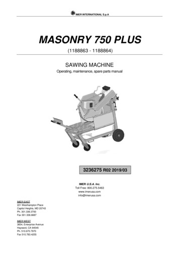
IMER INTERNATIONAL S.p.AFig. 1POS.1234ITelaioGuida scorrimentoCarrello portapezzoLeva bloccaggio carrello6Motore elettricoFChassisGlissiereChariotChariot calageProtectionéclaboussuresMoteur5Grembialina paraschizziMotorMotorEBastidorGuíaCarroCarro bloqueoProtección contrasalpicadurasMotor7Quadro elettricoBoiter electriqueElectric boardSchalttafelCaja electra8SpinaPlugStecker9Gruppo testa di taglioCutting head groupSchneidkopf-gruppe10111314DiscoCarter discoProtezione lama(OPTIONAL)Vasca acquaPompa acquaFicheGroupe tête decoupeDisqueCarter discProtection disque(OPTIONAL)CuvePompe eauBladeDisc coverBlade cover(OPTIONAL)DrumWater pump15Leva regolazione taglioLevier réglage coupeAdjusting cut lever1617Blocco testaManici spingi pezzobloc de têtepoignéesHead BlockhandlesTab AL)MischwanneWasserpumpeHebel po cabeza decorteDiscoCárterProtección disco(OPTIONAL)RecipienteBomba del aguaPalanca reglajecortebloque de cabezamanijas12GBFrameGuide barCarriageTrolley clampingDRahmenFührungWagenKarre einspannungSpray guardGummispritzschutzParticolare attenzione deve essere fatta alle avvertenze contrassegnate con questo simbolo :Il faut prêter une attention toute particulière aux notes précédées de ce symbole:Special attention must be given to warnings with this symbol:Lesen Sie die mit diesem Symbol bezeichneten Abschnitte mit besonderer Aufmerksamkeit:Se tiene que prestar una atención especial a las indicaciones marcadas con el signo:2
IMER INTERNATIONAL S.p.ADear Customer,Congratulations on your choice of purchase: IMER sawingmachines are the result of years of experience and areequipped with all the latest technical innovations.Disc rotation direction(view from the movable discguard)clockwiseCutting table dimensions490x660 mmOverall dimensions(width x length x height)850x1550x1600 mmOverall dimensions fortransport(width x length x height)850x1550x1600 mmWeight of saw in operation285 kgWeight for transport202 kg- WORKING IN SAFETYTo work in completeinstructions carefully.safety,readthefollowingThis OPERATION AND MAINTENANCE manual must be keptby the SITE MANAGER and be always available forconsultation.The manual should be considered as a part of the machineand must be kept for future reference, for the whole life of themachine. Should the manual be lost or damaged, areplacement copy can be ordered from the manufacturer.The manual contains important information regarding eprocedures, and requests for spare parts. Nevertheless, theinstaller and the operator must both have adequate experienceand knowledge of the machine prior to use.In order to ensure operator safety, safe operation and longservice life, it is imperative to adhere to the instructions set outherein and the requirements of the legislation in forcegoverning safety in the workplace. Use individual safetyequipment (suitable shoes and clothing, gloves, safetyglasses, etc.).Table ))Power (kW)2.25.5Rated t (A)13.811.6Rpm14201440Type P55Capacitor(µF)2 x 50- It is mandatory to wear protective goggles.- It is mandatory to use individual hearing protectors.- Make sure that all signs are legible.- It is strictly forbidden to carry out any form ofmodification to the machine structure and systems.IMER INTERNATIONAL accepts no responsibility in the eventof failure to comply with laws governing the use of this type ofequipment, with particular reference to: improper use, powersupply errors, lack of maintenance, unauthorised modification,and failure to comply, either wholly or partially, with theinstructions set out in this manual.IMER INTERNATIONAL reserves the right to modify featuresof the saw and/or the contents of this manual, without theobligation to update previous machines and/or manuals.12Max disc diameter750 mmDisc hole25.4 mmDisc revs (230V/50Hz)976 rpmDisc revs (400V/50Hz)1440 rpmDisc revs (400V/60Hz)1475 rpmDisc revs (220V/60Hz) SPH1180 rpmDisc revs (220V/60Hz) TPH1475 rpmMotor (220V - 60 1730S3S1S1FfFIP55IP 55IP55180. NOISE LEVEL AND VIBRATIONSTab 4 gives the sound pressure level of the machinemeasured at the ear of the operator when running empty(LPA) and vibrations transmitted when it is operating.ModelType ofmotorLpAAeqMasonry 750 PlusElectric95 dB2.33 m/s2- TECHNICAL DATAMasonry 750 PlusMotor(220 V 60 Hz)SPHTable 3TECHNICAL DATATechnical data are stated in Tab 2 and the electricalspecifications in Tab 3.ModelMotor(400V 60Hz)Table 43CUTTING SPECIFICATIONSThe sawing machine is designed to cut only bricks, ceramics,marble, granite, concrete products and similar items. Themachine must be used ONLY with segmented or continuousrim diamond cutting blades, which must be water-cooled at alltimes. The use of blades for dry cutting is strictly forbidden andthe machine must not be used to cut any material other thanthose included in this specification. IMER INTERNATIONALaccepts no responsibility for loss or damage resulting fromimproper use of the machine.3
IMER INTERNATIONAL S.p.Acarry the machine with a fork-lift truck, engage the forks in thespecial seats (ref. 2, Fig. 2).Being the machine mounted on wheels, it can be movedmanually on level surfaces in the following way:1. make sure the front wheel brakes are released.2. make sure that the workpiece trolley is blocked by means ofthe special ratchet (ref. 4,Fig. 2).3. acting on the handle of the workpiece trolley, tow themachine manually; the pivoting front wheels facilitate themovement even if not straight.4CUTTING CAPACITY (Disc diameter 750 mm) Maximum cutting capacity in one pass 300 mm Maximum height of the piece to be cut 430 mm Minimum width of the piece to be cut 50 mm Maximum cutting length with disc lowered 500 mm Maximum cutting length with disc descent from above 560mm5WARNINGDo not load the machine with pieces of excessive weight (maxKg 40). Pay attention to the stability of the machine: it must beinstalled on a stable base with a maximum inclination of 5 (Fig. 2). The machine is equipped with a brake on the front swivelwheels. Before starting the cutting operations, lock the wheelswith the brake. Pay attention to the stability of the pieces before, during andafter cutting: the pieces must not protrude out of the workingsurface in any case. Avoid spilling residual liquids from cutting by using suitablecontainers.9INSTALLATION1. Position the machine on a horizontal plane in a stable way.2. Lock the front wheels with the brakes.3. Unlock the trolley from the stop that fastens it to the head(ref. 4, Fig. 2).10ELECTRICAL MAINS CONNECTION- Ensure that voltage corresponds to machinedataplate specifications.The power supply line must be equipped with current overloadprotection (e.g. thermal-magnetic cutout) and protectionagainst indirect contact (e.g. residual current circuit breaker).The electrical power distribution board at the construction sitemust conform to the requirements of EN 60439-4.The electric cable wire size must take into account theoperating currents and length of the line to avoid excessivevoltage drops (Errore. L'origine riferimento non è statatrovata.-recommended values).6SAFETY MEASURESThe IMER saw is designed to operate on construction sitesand is not equipped with its own lighting; the work site must bewell illuminated (min. 500 lux).- Never use the saw in environments subject to therisk of explosions and/or fire.Cable (mm²)ModelType of motor2.54.0230 V -50 hz13.8 A0-10 11-30400 V - 50 Hz11.6 A0-10 11-30400 V - 60 Hz11.5 A0-10 11-306.0Cable length (m)1. The IMER sawing machine will only run if all the safetydevices are in place and in perfect condition.2. Do not use improvised and/or defective power supplylines.3. The connection lines on the site must be laid in such away that they cannot be damaged. Never stand the saw onthe power supply cable.4. The plug/socket connections must be protected fromwater. Use only connectors equipped with protectionagainst water jets (IP67).5. Repairs to the electrical installations must only becarried out by specialised personnel. Do not make anyadjustments or carry out any maintenance work while themachine is powered up or running.Masonry 750 Plus220 V 60 Hz SPH23.2 A0-2021 - 30220 V 60 Hz TPH21.6 A0-2021 -30Table 5-To stop the saw from working, use solely the specificswitch (ref. 7, Fig. 1).Check the integrity of the insulation and protective conductorof the electrical supply.Connect the machine plug to the electrical power supply andtighten the mechanical retainer ring with IP67 protection rating.The machine is now ready for operation.7ELECTRICAL SAFETYThe IMER sawing machine complies with current legislationand in particular it is equipped with: System for preventing unwanted start-up on return of powerafter a power failure. Protection against short circuits. Thermal cut-outs protecting the motor.811COMMISSIONING THE MACHINEBefore connecting the machine to the electric mains:1. Check that the tank contains a sufficient amount of coolingwater (minimum 60 l, maximum 90 l).2. Make sure that the power supply mains complies with therequirements of paragraph 10 "Electrical mains connection".3. Then disconnect the machine on the power supply line.4.1. For the machine with 230V/50Hz motor: press the starterswitch on the electrical panel. TRANSPORTABILITY- Before removing the sawing machine, lock thetrolley by acting on the stopper (ref. 4 -Fig. 2).To lift the machine, use a three-boom tie rod (ref. 1, Fig. 2),engaging the hooks in the special connections (ref. 3, fig.4). To4
IMER INTERNATIONAL S.p.A4.2. For the machine with 400V/50Hz motor: Check that thedirection of rotation of the blade is in accordance with thearrow on the guard. Do not use the machine in areas exposed to the risk of fire.The cutting process may generate sparks, which could causefires or explosions. Transport and position the machine only after disconnecting itfrom the power supply. Always make certain that the disc is not in contact with anythingbefore starting the motor.- Otherwise, turn the selector on the electric plug witha screwdriver. Check again that the direction of rotation ofthe blade is in accordance with the arrow on the guard5. Adjust the cooling water flow turning the special tap on theback of the machine next to the cutting head (no dry cutsshould be made).6. If everything is in order, the work can begin.12- Check that the disc guard is in place. Before starting work, fill the tank with water. Restore the levelduring use, when it becomes necessary. The pump mustalways remain submerged. Insert the power plug.STOPPING THE SAWING MACHINE- The sawing machine can be stopped by pressing- It is absolutely forbidden to remove the guards ofthe button on the electrical panel (ref7 - Fig. 1).To start the machine again, turn the button and then pressthe start button (ref7 - Fig. 1).13the machine.- The electric motor is protected against thermaloverload: this protection intervenes stopping the machine,after which it is necessary to wait for the time necessaryto the thermal device to cool down before it is possible torestart the machine.DISC ASSEMBLY- The disc must be assembled after stopping themachine and disconnected the power supply.1. Remove the water pipe after having loosened the fasteningelement (ref. 4Fig. 3).2. Unscrew the three screws that fasten the movable part ofthe disc guard using the special key supplied (ref. 3, Fig. 3).3. Loosen the lock nut (ref. 1, Fig. 3) turning it clockwise (leftthread).4. Remove the movable flange (ref. 2, Fig. 3). Check fordamage on flanges, disc shaft and disc.14.1with the saw machine off and disconnected power supply.To raise or lower the disc, turn the lever (ref. 15, Fig. 1) to thedesired height from the cutting table and tighten the lockinglever (ref. 16, Fig. 1).- Make certain that the locking knob is properly- Do not use damaged discs, with missing sectors.tightened before starting the work.- Use only discs that are suitable for the rpm shownon the machine data plate.14.2CuttingDuring cutting operations it is mandatory to place both handson the push handles of the trolley (ref. 17, Fig. 1)It is also mandatory to wear the necessary personal protectiveequipment such as:- gloves- eye protection- earphones for noise protection- Check that the direction of rotation of the disc is thesame as marked on the disc guard.5. Center the disc on the fixed flange, position the movableflange (ref. 2, Fig. 3) and correctly lock the locknut (ref. 1, Fig.3) of the disc turning it anticlockwise (left thread).6. Refit the movable part of the disc housing, fastening it withthe respective screws (ref. 3, Fig. 3).7. Re-insert the water pipe and tighten the fastening elementuntil the pipe is locked (ref. 4, Fig. 3- Check the alignment of the disc with the cuttingline.- Check that the disc housing is well secured.1. Place the piece to be cut on the workpiece trolley (ref. 3,Fig. 1), resting firmly against the fixed stop.2. Start the motor.3. Wait until the water reaches the disc.4. Make sure that nothing is in the cutting area that can hinderthe cutting phase5. Start cutting.6. The horizontal cutting movement is achieved by manuallymoving the workpiece trolley towards the disc.- An incorrectly assembled disc can cause damage tothe machine and to people.- Note that the disc must have external diameter of750 mm, central hole diameter of 25.4 mm and maximumthickness of 4 mm.- Make certain that the disc to be used is suitable forthe material to be cut.- It is forbidden to use wooden discs.14Vertical movement of the disc- All disc adjustment operations must be carried out- A greater effort is required to the disc for cutting aworkpiece with greater height. Therefore, in order not tooverload the motor, the operator must adjust the carriagespeed. This speed also depends on the characteristics ofthe material to be cut (hardness, toughness, etc.).USE- Leave at least 1.5 m of free space around themachine to operate safely. Use the machine within the temperature range 0 - 40 C. Do not allow anyone else to remain in the vicinity of themachine during cutting.14.3Cut from aboveUnlock the cutting head acting on the locking lever (ref. 16 Fig.1), position the piece to be cut, start the sawing machine and5
IMER INTERNATIONAL S.p.Astart cutting from above acting on the head lever (ref. 15, Fig.1).16.4Runners cleaningIt is advisable to remove any trace of dirt that may haveformed on the runners.14.4Changing the discTo change the disc refer to the "Disc assembly" paragraph.16.5Cleaning and maintenance of the cooling systemIf no water is reaching, stop cutting immediately to avoiddamaging the blade.Stop the machine and check that there is sufficient water in thetank.If necessary, unplug the machine and check that the pump tap,hose or filter is not blocked.15Use of cutting disc diameter 700 mmA cutting disc with a diameter of 700 mm can be installed onthe machine. The operation requires the cutting head strokecalibration, an operation carried out as standard by themanufacturer for a 750 mm diameter disc. Since thisadjustment, if carried out incorrectly, can damage the machineand cause risks for people, it is recommended that it is carriedout by skilled and qualified personnel.Proceed as follows:1. Make sure that the machine is disconnected from the powersupply.2. Fit the 700 mm diameter disc according to the procedureindicated in the "Disc Assembly" paragraph.3. Loosen the knob (ref. 16, Fig. 1).4. Lower the cutting head until the disc is in the best cuttingposition (the outer diameter of the disc must protrude 15 mmfrom the cutting table).5. Turn the screw until the desired height adjustment isobtained and then tighten the knob (ref. 16, Fig. 1).At this point the cutting head is adjusted for a 700 mmdiameter disc.16.6Drive belt tensioning1. Stop the saw and disconnect the power plug.2. Unscrew the 4 screws that block the movable guard of thebelt (ref. 1, Fig. 4).3. Loosen the 4 nuts (ref. 2,Fig. 4) that tighten the electricmotor on the disc holder boom.4. Pull the belt acting on the nuts (ref. 3, Fig. 4), the correcttensioning of the belt must be checked by means of a specialinstrument to measure the vibration frequency of the belt, thereference values to be considered are shown in the tablebelowType of motor400V - 50Hz220 V - 50Hz400 V - 60 Hz220 V - 60 Hz- If it is necessary to reassemble a 750 mm diameterdisc, it is necessary to repeat the adjustment, restoringthe factory setting.- Note that the disc must have external diameter of700 mm, central hole diameter of 25.4 mm and maximumthickness of 4 mm.16Reference values for belt tensionNew (Hz)Run in (Hz)47 Hz /- 2%45 Hz /- 2%45 Hz /- 2%43 Hz /- 2%47 Hz /- 2%45 Hz /- 2%45 Hz /- 2%43 Hz /- 2%Table 65. Tighten the nuts of the electric motor (ref. 2, Fig. 4),checking the alignment of the motor pulley and the disc pulley.6. Refit the belt guard and lock it with the 4 screws (ref. 1, Fig.4).MAINTENANCE- Maintenance must be done by adequately trained16.7Replacing the drive belt1. Switch off the electric motor and disconnect the power plug.2. Unscrew the 4 screws that block the movable guard of thebelt (ref. 1, Fig. 3).3. Loose (ref 2 Fig. 4) that tighten the motor plates (ref. 137,TAV2) on the disc holder boom.4. Loosen the belt acting on the nuts (ref. 3, Fig. 4) andreplace it with the new one.5. Pull the belt acting on the nuts (ref. 3, Fig. 4):the correcttension measured with frequency meter must be equal to thevalue shown in Tab 6.6. Tighten the nuts on the motor plates (ref. 2, Fig. 4),checking the alignment of the motor pulley and the disc pulley.7. Refit the belt guard and lock it with the 4 screws (ref. 1, Fig.4).personnel, after switching off the electric motor, anddisconnected the power plug.- Check the condition of the power cable beforestarting to use the machine: someone may haveinadvertently and/or unconsciously damaged it.- Make sure the guards/safety equipment are alwaysfunctional and in good condition.In particular, keep the blade guards efficient and clean, takingcare to replace them in case of damage.Do not leave the machine outdoors: it must be protected fromweather.The cleaning operations to be carried out at the end of eachwork shift are indicated below.16.1Tank cleaningEmpty the tank, removing the cap. Remove the cutting depositformed using a jet of water.16.8Repairs- All maintenance operations must be performedexclusively with the machine switched off, and the powerplug disconnected from the mains.16.2Tank disassemblingEmpty the tank opening the cap and remove the tank laterallyfrom the right or left side.- If any guards are removed for repairs, ensure theyare correctly refitted at the end of work.Use exclusively original IMER spare parts; modifications toparts are strictly prohibited.16.3Reference tables cleaningThe support tables must be kept clean. Deposits of dirt canadversely affect the precision of cutting.6
IMER INTERNATIONAL S.p.AGrinding/cutting/drilling of masonry, concrete, metal and othermaterials with silica in their composition my give off dut or mistscintainig crystalline silica. Silica is a basic component of sand, quartz,brick clay, granite and numerous other minerals and rocks. Repeatedand/or substantial inhalation of airborne crystalline silica can causeserious or fatal respiratory diseases, including silicosis. In addition,California and some other authorities have listed respirablecrystallinesilica as a substance known to cause cancer. Whwn cuttingsuch materials, always follow respiratory precautions.17RESIDUAL RISKS AND SAFETY NOTICESAlthough the sawing machine has been manufactured fully incompliance with current regulations, residual risks exist thatcannot be eliminated and involve the use of appropriateindividual protection devices. The machine is equipped withnotices to indicate the residual risks and how to avoid them.NOISE HAZARDWear ear defendersUse appropriate NIOSH-approved respiratory protection where dusthazard may occur. Paper masks or surgical masks without a NIOSHapproval number are not recommended because they do little toprotect the worker. For more information about respirator programs,including what respirators have received NIOSH approval as safe andeffective, please visit the NIOSH website at:http://www.cdc.gov/niosh/topics/respiratorsHAND CRUSHING/SHEARING HAZARDWear glovesEYE INJURY HAZARDObserve OSHA regulations for respirator use (29 C:F.R. § 1910.134).Visit http://www.osha.gov for more information.Wear safety glassesCalifornia proposition 65 messageSome dust created by power sanding, sawing, grinding, drilling, andother construction activities contain chemicals know (to the State ofCalifornia) to cause cancer, birth defects or other reproductive harm.Some examples of these chemicals are:INCORRECT USE HAZARDRead the manual before operating themachine-Lead, from lead-based paints-Crystalline silica, from bricks and cement and other masonryproducts-Arsenic and chromium, from chemically treated lumberCutting with water is compulsoryFor further information , consult the following P65warnings.ca.govTRAPPING/CRUSHING AND SHEARING HAZARDDo not remove the guardsYour risk from these exposures varies depending on how often you dothis typer of work. To reduce your exposure to these chemicals, workin a well-ventilated area, and work with approved safety equipment,such as dust masks that are specially designed to filter outmicroscopic particles. Where use of a dust extraction device ispossible, it should be used. To achieve a high level oof dustcollection, use an industrial HEPA vacuum cleaner. Observe OSHA29 CFR part 1926.57 and 1926.103.18TROUBLESHOOTING- CAUTION!!! All maintenance operations must beperformed exclusively with the machine stopped off andthe power plug disconnected from the mains.Do not touch drive componentsDanger of cuttingELECTROCUTION HAZARDProblemDanger - electrical powerMotor fails to startwhen switch isoperatedNote that the employer is responsible for ensuring his workersuse individual safety equipment.SILICA DUST WARNING7CausesCorrective actionVoltage not reachingsupply lineCheck the line *Electrical socket andplug are not properlyconnectedRestore correctconnectionThe power cable fromthe plug to the panel iscut offChange the cable *
IMER INTERNATIONAL S.p.ADifficult trolleyhorizontal slidingNo cooling waterreaching discAn electrical wire in themotor terminal board isdisconnectedRestore theconnection *An electrical wire in theelectrical panel isdisconnectedRestore theconnection *The ON switch is faultyReplace the switch *A fuse has blownReplace the fuse *The thermal safetydevice has beentriggeredWait a few minutesand try againDirty runnersClean the runnersRefer to "cleaning and maintenance of thecooling system" (par. 17.5)The disc is wornReplace with newdiscTransmission belt nottensionedTighten the beltsBelt brokenReplacing the drivebeltDisc fails to cutMotor starts but discdoes not turn* Operation to be carried out by an electricianTools supplied double-ended wrench CH 10-13 open ended wrench CH 368
IMER INTERNATIONAL S.p.AINSTRUCCIONES TRADUCIDASApreciado Cliente:Enhorabuena por su compra, la sierra IMER es el resultado deaños de experiencia e incorpora soluciones técnicasinnovadoras para ofrecer la máxima fiabilidad.- TRABAJAR CON SEGURIDADPara trabajar en condiciones seguras es fundamental leercon atención las siguientes instrucciones.El presente manual de USO Y MANTENIMIENTO debe serconservado en las obras por el CAPATAZ y estar siempredisponible para que pueda consultarse en cualquier momento.El manual debe considerarse parte de la máquina yconservarse hasta el final de su vida útil para futurasconsultas. Si se pierde o se daña, solicite un nuevo ejemplaral fabricante.El manual contiene importantes indicaciones sobre lapreparación del obrador y la instalación, el uso, mantenimientoy pedido de repuestos de la máquina. De todas formas, esindispensable que el técnico de mantenimiento y el usuariotengan experiencia y un conocimiento adecuado de lamáquina.Para garantizar la seguridad del operador, un funcionamientocorrecto y una larga duración del equipo, deben respetarse nosólo todas las instrucciones del manual sino también lasnormas de seguridad y prevención de accidentes laboralesestablecidas por la legislación vigente. Haga uso de lasprotecciones individuales (calzado y ropa adecuados, guantes,gafas, etc.).Elusodemediosdeprotecciónauditiva- Mantener siempre legibles las señales.- Se prohíbe modificar de cualquier modo laestructura o las distintas partes de la máquina.IMER INTERNATIONAL declina toda responsabilidad cuandono se respeten las leyes que regulan el uso de estos equipos,y, en concreto: uso indebido, errores de alimentación, falta limiento total o parcial de las instrucciones ilustradasen este manual.IMER INTERNATIONAL se reserva el derecho de modificarlas características de la sierra y el contenido del manual sinobligación de actualizar la máquina o los manualesprecedentes.750 mmOrificio del disco25,4 mmRevoluciones del disco (230V/50 Hz)Revoluciones del disco (220V/60 Hz) SPH1180 rpmRevoluciones del disco (220V/60 Hz) SPH1475 rpmSentido de rotación deldisco(vista desde el cárter deldisco móvil)horarioMedidas de la mesa decorte490x660 mmMedidas(ancho x largo x alto)850x1550x1600 mmMedidas para transporte(ancho x largo x alto)850x1550x1600 mmPeso de la sierra en servicio285 kg202 (400 V/50Hz)Motor (400V - 60 Hz)Motor(220 V 60 Hz)SPHMotor(220 V 60 Hz)TPHPotencia (kW)2.25.55.545.5Tensiónnominal (V)220240400400220220Frecuencia (Hz)5050506060Corrienteabsorbida 4017401730Tipo de servicioS1S3S3S1S1Clase deaislamientoFFFfFGrado deprotecciónIP55IP55IP55IP55IP55Condensador(µF)2 x 501802 . NIVEL DE EMISIÓN SONORA Y VIBRACIONESTRANSMITIDASEn la Errore. L'origine riferimento non è stata trovata. figura elnivel de presión sonora medido en el oído del operador envacío (LPA) y de las vibraciones transmitidas durante eltrabajo.- DATOS TÉCNICOSDiámetro máximo del disco1475 rpmTabla 31DATOS TÉCNICOSLos datos técnicos figuran en la Errore. L'origine riferimentonon è stata trovata. y las características eléctricas en laErrore. L'origine riferimento non è stata trovata.Masonry 750 PlusRevoluciones del disco (400V/60 Hz)Tabla 2individuales es obligatorio.Modelo1440 rpmPeso para trasporte- El uso de gafas de protección es obligatorio.-Revoluciones del disco (400V/50 Hz)ModeloTipo demotorLpAAeqMasonry 750 PlusEléctrico95 dB2.33 m/s2976 rpmTabla 49
IMER INTERNATIONAL S.p.A Sistema contra el arranque fuera de tiempo tras un corte deenergía eléctrica. Protección contra cortocircuitos. Protección térmica del motor.3 HERRAMIENTAS DE CORTELa sierra está diseñada para cortar solamente ladrillos,cerámica, mármol, granito, productos de cemento y similares.Deben emplearse exclusivamente hojas de diamante concanto de corte continuo o en sectores, refrigerados por agua.No utilice por ningún motivo hojas para corte en seco, ni cortemateriales distintos de los indicados. IMER INTERNATIONALdeclina toda responsabilidad por daños derivados de un usoimpropio de la máquina.8 . TRANSPORTE- Antes de desmontar la sierra bloquear el carromediante el bloqueo de seguridad (ref. 4 -Fig. 2).Para levantar la máquina, use un tirante de tres brazos (ref. 1,Fig. 2), fijando los ganchos en los conexiones especificas (ref.3, fig. 4). Para transportar la máquina con una carretillaelevadora, introducir las horquillas en las sedes específicas(ref. 2, Fig. 2).Al estar la máquina montada sobre ruedas, se puede movermanualmente sobre superficies planas de la siguiente manera:1. Asegúrese de desbloquear los frenos de las ruedasdelanteras.2. Asegúrese de que el carro que sujeta la pieza estébloqueado por medio del trinquete especial (ref. 4,Fig. 2.3. Actuando sobre el mango del carro que sujeta la pieza,remolque la máquina manualmente; las ruedas delanteraspivotantes facilitan el movimiento incluso no recto.4 CAPACIDAD DE CORTE (Diámetro del disco 750 mm) Capacidad de corte máxima en una sola pasada 300 mm Altura máxima de la pieza que se va a cortar: 430 mm Anchura mínima de la pieza que se va a cortar: 50 mm Longitud de corte máxima con disco bajado 500 mm Longitud de corte máxima con bajada vertical del disco 560mm5 ADVERTENCIAS No cargue en la máquina piezas de peso excesivo (máx 40kg). Preste atención a la estabilidad de la maquina: debe estarinstalada sobre un plano horizontal estable con una inclinaciónmáxima de 5 (Fig. 2). La máquina está dotada de freno en las ruedas delanteraspivotantes. Antes de comenzar las operaciones de corte,bloquee las ruedas con el freno. Preste atención a la estabilidad de las piezas antes, durantey después del corte: en ningún caso las piezas debensobresalir de la mesa de trabajo. No vierta en el medio ambiente los líquidos residuales delcorte; coloque recipientes apropiados para recogerlos.9 INSTALACIÓN1. Coloque la máquina en un plano horizontal de formaestable.2. Bloquee las ruedas delanteras con los frenos.3. Suelte el carro del blo
Hebel fuer Schneidensregulierung Palanca reglaje corte 16 Blocco testa bloc de tête Head Block Kopfblock bloque de cabeza 17 Manici spingi pezzo poignées handles Griffe manijas Tab 1 . The IMER saw is designed to operate on construction sites and is not equipped with its own lighting; the work site must be well illuminated (min. 500 lux). .