Transcription
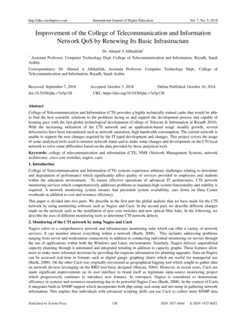
http://ijhe.sciedupress.comInternational Journal of Higher EducationVol. 7, No. 5; 2018Improvement of the College of Telecommunication and InformationNetwork QoS by Renewing Its Basic InfrastructureDr. Ahmed A Alkhalifah11Assistant Professor, Computer Technology Dept. College of Telecommunication and Information, Riyadh, SaudiArabiaCorrespondence: Dr. Ahmed A Alkhalifah, Assistant Professor, Computer Technology Dept., College ofTelecommunication and Information, Riyadh, Saudi ArabiaReceived: September 7, 2018doi:10.5430/ijhe.v7n5p138Accepted: October 3, 2018Online Published: October 10, 2018URL: ge of Telecommunication and Information (CTI) provides a highly technically trained cadre that would be ableto find the best scientific solutions to the problems facing us and support the development process and capable ofkeeping pace with the fast-global technological development (College of Telecom & Information in Riyadh 2010).With the increasing utilization of the CTI network and an application-based usage steadily growth, severaldeficiencies have been encountered such as network saturation, high bandwidth consumption. The current network isunable to support the new changes required by the IT rapid development and changes. This project covers the usageof some analytical tools used to monitor network status and to make some changes and development on the CTI localnetwork to solve some difficulties based on the data provided by those analytical tools.Keywords: college of telecommunication and information (CTI), NMS (Network Management System), networkarchitecture, cisco core switches, nagios, cacti1. IntroductionCollege of Telecommunication and Information (CTI) systems experience arbitrary challenges relating to downtimeand degradation of performance which significantly affect quality of services provided to employees and studentswithin the education environment. To ensure effective operations of advanced IT architectures, CTI networkmonitoring services which comprehensively addresses problems to maintain high system functionality and stability isrequired. A network monitoring system ensures that persistent system availability, cuts down on Data Centeroverheads in addition to cost and resource efficiency.This paper is divided into two parts. We describe in the first part the global analytic that we have made for the CTInetwork by using monitoring software such as Nagios and Cacti. In the second part, we describe different changesmade on the network such as the installation of new core switches and new optical fiber links. In the following, wedescribe the uses of different monitoring tools to determine CTI network defects.2. Monitoring of the CTI network by using Nagios and CactiNagios refers to a comprehensive network and infrastructure monitoring suite which can offer a variety of networkservices. It can monitor almost everything within a network (Barth, 2008). This includes addressing problemsranging from server and workstation connectivity in addition to conducting individual monitoring on servers throughthe use of applications within both the Windows and Linux environments. Similarly, Nagios delivers unparalleledcapacity planning through it automated and integrated trending in addition to capacity graphs. These features allowusers to make more informed decisions by providing the requisite information for planning upgrades. Data on Nagioscan be accessed real-time in formats such as digital gauge, graphing charts which are useful for managerial use(Barth, 2008). On the other Cacti was originally envisioned as geographical logging tool which sought to gather dataon network devices leveraging on the RRD tool basic designed (Haiyan, 2004). However, in recent years, Cacti aremade significant improvements on its user interface to brand itself as legitimate open-source monitoring projectwhich progressively continues to introduce new features. In retrospect, Nagios is considered to demonstrateefficiency in systems and resources monitoring due to its powerful Nagios Core (Barth, 2008). In the context of Cacti,it integrates built-in SNMP support which incorporates both php-snmp, ucd-snmp and net-snmp in gathering networkinformation. This implies that individuals with advanced scripting skills can use Cacti to collect more SNMP dataPublished by Sciedu Press138ISSN 1927-6044E-ISSN 1927-6052
http://ijhe.sciedupress.comInternational Journal of Higher EducationVol. 7, No. 5; 2018from the network.This part of the study will be structured into three sections; the first section offers an overview of CTI networktechnology SNMP based network management. The subsequent second section evaluates the design of commonCTI MIB. It also highlights the design and implementation of our CTI NMS. In the third section, the focus will beon the experimental result on the small CTI testbed.2.1 Overview of CTI Network2.1.1 InfrastructureThe CTI mapping represents a corporate campus network which is designed to connect buildings includingadministrative, academic, college libraries, student centers, residence halls, gymnasiums, and other outlyingstructures, like conference centers, technology centers, and training institutes. CTI networks are normallyinterconnected with high-speed Ethernet links operating over optical fiber such as Gigabit Ethernet as shown inFigure (1).Figure 1. Overview of CTI Network DiagramMany tools have emerged to aid in performance monitoring of networks. In recent years, there has been emergenceof many system tools designed to monitor performance of networks. Most of these tools are conventionally based onthe Simple Network Management Protocol (SNMP) (William stalling, 2002) (Harrington, Presuhn, Wijnen, 2002) aprotocol used on IP networks for sending and transmission of information relating network performance. Othervarieties of tools in monitoring network performance include packet sniffers, flow monitors, and applicationmonitors. Some of the prominent examples of these tools include Solar Wind's Orion SNMP monitoring platform,WireShark packet capture tool, Web metrics' Global Watch, and Cisco's NetFlow flow monitoring tools.Currently, CTI network is composed of the following infrastructure devices:1) Cisco 4500 series switches (Core).2) Cisco 3500 series switches (Distribution).3) Cisco 2900 series switches (Access)4) HP 1810 switches (Access)5) Cisco 1900 series router (ISP and IPVPN)6) Cisco 2800 series router (Voice Gateway)7) Huawei VDI (Virtual Desktop Infrastructure System)8) Windows 2012 Server (CCTV System)9) Windows 2008 Server (Domain Controller)Published by Sciedu Press139ISSN 1927-6044E-ISSN 1927-6052
http://ijhe.sciedupress.comInternational Journal of Higher EducationVol. 7, No. 5; 201810) Windows 2000 Server (Call Manager)11) Aruba Network (Access Point)Until now, network devices such as Cisco switches include defined CTI MIBs in addition to a SNMP agent appliedon those devices, other devices are currently focused on defining CTI MIBs on their respective SNMP supportedversion. Typical CTI networks will probably incorporate CTI devices from more than one vendor probablydeveloped utilizing different SNMP version. However, for the SNMP manager to manage these hybrid devices, acommon and standard MIB which defined is require in addition to implementation in all of these devices.The current work consists on defining a common CTI MIB. Also, a CTI network Management System wasdeveloped using Cacti and Nagios which is based on common CTI MIB. The system facilitates the detection of CTIfaults, recovery, network configuration, network performance monitoring by network administrators.In the next section, we propose a free and open source application which also focuses on system and networkperformance which are Cacti and Nagios.2.1.2 CTI Network ManagementCurrently, CTI is using the secured version of SNMP which is the Version 3. The two applications that monitor thesystem or network of CTI now are CACTI and Nagios. The following is a brief description of each one of them andhow it was sued in CTI. Cacti is an open source web-based network and system monitoring graphing solution for IT infrastructuremanagement. Cacti allow an administrator to poll services at regular intervals to create graphs on the resultingdata. Commonly, it is used to graph time-series data on metrics such as network bandwidth utilization, runningprocesses, CPU-Memory-Disk usage (Urban, 2017). Nagios is a freeware computer-software used for systems, networks and infrastructure monitoring, Nagiosprovides monitoring and alert services for servers, switches, applications, and services. It alerts users on systemfaults, and subsequent alert after the problem has been solved (Michael Guthrie Instant Nagios Starter May,2013).2.2 Design and Implementation2.2.1 DesignWe designed our CTI-NetMon to support the CTI network as demonstrated in Figure 2. It does not represent ageneric topology, but serves as an example of the CTI network, which we would like to manage using the systemproposed. Our main interest has been to manage the CTI devices utilizing SNMP. The system is designed tomanage the faults, performance, and the main NMS features configuration.Figure 2. Proposed CTI Network ArchitecturePublished by Sciedu Press140ISSN 1927-6044E-ISSN 1927-6052
http://ijhe.sciedupress.comInternational Journal of Higher EducationVol. 7, No. 5; 20182.2.2 ImplementationWe have established our CTI-NetMon part using LAMP (Linux-Apache-MySQL-PHP) solution. SNMP version 3has been chosen to add cryptographic security (Gerner, Naramore, Owens, Warden, 2005). The following packageswere installed on the POC (Proof of Concept) machine. Apache: A Web server to display network graphs created by PHP and RRD Tool. MySQL: A Database server to store cacti information. PHP: A script module to create graphs using RRD Tool. PHP-SNMP: A PHP extension for SNMP to access data. NET-SNMP: A SNMP (Simple Network Management Protocol) is used to manage the network. RRD Tool: A database tool to manage and retrieve time series data like CPU load, Network Bandwidth etc.2.2.3 Experiment2.2.3.1 Experiment Environment SetupWe have made the SNMP Manager on POC (Proof of Concept) machine as described in Figure 3. We have installed aCacti Version 0.8.8h and Nagios Core Version 4.1.1.Figure 3. Proof of Concept of CTI-NetMonThe NMS Agent was configured on network switches using SNMP version 3 as shown in Figure 4.Figure 4. Configuration example on network switches2.2.3.2 Experiment ResultTo be more proactive on our daily routine, we put a four-big screen (43 inches TV) on our location with the speakerto hear the alarm if there is a down device or services that are having an issue. Figure 5 and Figure 6 shows thesample Tactical Overview of Nagios Core and Nagios XI. Figure 7 shows the preview of Graphs plugin which allowsus to view the actual inbound and outbound traffic utilization.Published by Sciedu Press141ISSN 1927-6044E-ISSN 1927-6052
http://ijhe.sciedupress.comInternational Journal of Higher EducationVol. 7, No. 5; 2018Fig 4-4Fig4-3Figure 5. Main page of NagiosFigure 6. Tactical overviewPublished by Sciedu Press142ISSN 1927-6044E-ISSN 1927-6052
http://ijhe.sciedupress.comInternational Journal of Higher EducationVol. 7, No. 5; 2018Figure 7. Traffic in different buildings3. CTI Infrastructure RenewThis part is structured into two main sections. The first section highlights the overview of the new consideration suchas replacing the core switches. Section II presents the new design of the fundamental transmission cables.3.1 Deploy New Core SwitchesCTI network topology is based on traditional data center network infrastructure. The data center networkinginfrastructure is designed to ensure that multiple data center tenants with different varieties of workloads can beaccommodated. The coordination between the servers and clients within the network needs data center networkingfor the resources. The infrastructure consists of a 3-layer hierarchical model. It entails the core layer switches whichlink to distribution layer switches, which subsequently links to access layer switches.Published by Sciedu Press143ISSN 1927-6044E-ISSN 1927-6052
http://ijhe.sciedupress.comInternational Journal of Higher EducationVol. 7, No. 5; 2018Figure 8. Basic Network TechnologyUsing our monitoring tools and experimental tests were done by our network managers and described previously, wenoticed that the previous infrastructure suffers from:1.Network Congestion making a traffic slow-down2.Massive use of bandwidth even outside of peak working hours3.Loss of the internal connection several times4.Problems of data storage and data recovery5.Defeat of some servers without a clear cause6.Weakness of the internet connection and sometimes total disconnection7.Difficulties in the integration of new applications8.Difficulties in connecting virtual machines such as VDI (Virtual Desktop Infrastructure)Figure 9 represents the basic infrastructure of the CTI. Given the results obtained before, we decided to change alarge part of our network. We started in the first phase by changing the architectural levels like the distribution of themain devices (servers, routers, and switches) and in the second phase, we changed completely the infrastructure ofour network by replacing the old cables with new optical fiber.Published by Sciedu Press144ISSN 1927-6044E-ISSN 1927-6052
http://ijhe.sciedupress.comInternational Journal of Higher EducationVol. 7, No. 5; 2018Figure 9. basic CTI network infrastructureFigure 10. Old core switchesPublished by Sciedu Press145ISSN 1927-6044E-ISSN 1927-6052
http://ijhe.sciedupress.comInternational Journal of Higher EducationVol. 7, No. 5; 2018Figure 11. New core switchesFeatures of the new core switches (Cisco):Cisco Catalyst 6509-E Switch 9 slots, 14 RU 32 x 40 GE ports 130 x 10 GE ports 387 x 1 GE ports 385 x 10/100/1000 ports Forwarding capacity up to 510 Mpps3.2 Deploy New Fiber InfrastructureIn this part, we describe the architecture of the optical fibers and the different links between the main equipment.Figure 12. represents the old cabling infrastructure in different floors.Published by Sciedu Press146ISSN 1927-6044E-ISSN 1927-6052
http://ijhe.sciedupress.comInternational Journal of Higher EducationVol. 7, No. 5; 2018Figure 12. Traditional hierarchical topologiesTo work in a deterministic order during various types of planned and unplanned outages, our network must simplifyoperations, optimize application performance and build resilience. The purpose of this task is to limit the effort onconcentrating a solid foundation and a solid infrastructure between the accesses, distribution and core systems of ourcampus. It must certainly cover all the recommendations to be applied to different types of platforms according totheir roles in the network.We began the planning process by segmenting devices and equipment into hierarchical functions. This identifies thetype of operations and defines logical plant network segmentation for each level Figure 13.Published by Sciedu Press147ISSN 1927-6044E-ISSN 1927-6052
http://ijhe.sciedupress.comInternational Journal of Higher EducationVol. 7, No. 5; 2018Figure 13. New hierarchical topologyThe concentration of fibers in star topology reduces their used lengths during the installation. Further, it lowers thechances of network failure through connecting all systems to a central node. The typology is often consideredbeneficial because it is relatively easy to manage, install, configure and fault detection and removal of parts. The useof a central node in the star typology creates dependency and the risk to failure of the whole network where thecentral node is disabled. Additionally, other problems appear such as the degradation of the transmission quality andthe difficulties of the interventions. The new fiber distribution consists of dividing the overall architecture of thefibers into small pieces giving the hand to a manipulation and administration of the smaller parts which are easier tomanage. The following is a comparison table between before and after.Table 1. Comparison between before and afterBeforeAfterNet speed (Mbit/s)1254Downtime numberOnce permonthNo downtimeSwitchescongestiontwice permonthNo congestionIn research, it was established that despite the positive results of the NetMon, the findings are limited to networkssimilar to the same require requirements we used. There is need to for further research to establish the scalability ofthe system in the context of large network systems. Based on the available data from the experiments in the currentstudy, it is not possible for the researcher to project the efficiency of the system on much larger scale.4. ConclusionIn summary, we concisely introduce in a first part the CTI infrastructure and encouraged the importance of the CTInetwork Management System. In the paper, we demonstrated the design of the common architecture ofPublished by Sciedu Press148ISSN 1927-6044E-ISSN 1927-6052
http://ijhe.sciedupress.comInternational Journal of Higher EducationVol. 7, No. 5; 2018SNMP-based network management, design and implementation of CTI NMS called NetMon for the hybrid CTInetworks. We undertook installation of Cacti and Nagios to test the system that was proposed on the POC machinewhere we installed CTI NetMon for ourselves and presented the test result on the network management section ofthis paper. In a second part, we have described the steps taken to improve our network infrastructure, in fact we havetried to sweep the limits and drawbacks of our network infrastructure by replacing the distribution of the main devicelike core switches and also by adopting a new architecture, which consisted of dividing the network into small cellsand completely changing the transmission media with more consistent optic fibers.This work is a description of a set of steps and decisions we took to improve the performance of Our network. Thiswork could serve as a manual for other institutions that want to improve their networks. However, there should besome limitations to be taken in consideration including the network size and the intended user capacity. As it wasdescribed before, the project was done in an educational institute which usually has high volume demand on networkservices in certain times during the day, which might not be the case in other situations.AcknowledgementsThis work was supported by General Administration for Research and Studies in TVTC Corporation, member ofResearch Team – Dr. Mohsen DENDEN and by the System/Network Engineering Team support program supervisedby the Head– Engr. Fahad Aljomah.ReferencesAljomah, Fahad. (2017). Exploring the Use of Network Management System By Cacti & Nagios Software InCollege Campus. Proceedings of 73rd ISERD International Conference, Bali, Indonesia, 13th -14th May 2017,ISBN: 978-93-86291-88-2.Barth W. (2018). Nagios: System and network monitoring. No Starch Press; 2008 Oct be.com/watch?v uthrie, Michael. (2013). Instant Nagios Starter. Packt Publishing Ltd, 2013.Gerner J, Naramore E, Owens M, Warden M. (2015). Professional LAMP: Linux, Apache, MySQL and PHP5 WebDevelopment. John Wiley & Sons; 2005 Dec 13.Harrington D, Presuhn R, Wijnen B. (2002). An architecture for describing simple network management protocol(SNMP) management frameworks. 2002.Haiyan LY. (2008). The application of cacti in the campus network traffic monitoring. Computer &Telecommunication.Urban T. (2017). Cacti Beginner's Guide: Leverage Cacti to design a robust network operations center. PacktPublishing Ltd; 2017 Dec 27.William Stalling SNMP, SNMPv2, SNMPv3, and RMON 1&2, 3e 2002.Published by Sciedu Press149ISSN 1927-6044E-ISSN 1927-6052
protocol used on IP networks for sending and transmission of information relating network performance. Other varieties of tools in monitoring network performance include packet sniffers, flow monitors, and application monitors. Some of the prominent examples of these tools include Solar Wind's Orion SNMP monitoring platform,