Transcription
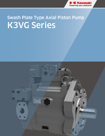
Swash Plate Type Axial Piston PumpK3VG Series
CONTENTSApplications/Product Usage3Safety Precautions4Conversion Factors and Formula5General Descriptions and Features71. Ordering Code1-1. Pump Options81-2. Regulator Options92. Technical Information2-1. Technical Data10 - 122-2. Specifications132-3. Functional Description of Regulators14 - 172-4. Power Setting Codes18 - 192-5. Performance Data20 - 252-6. Bearing Life26 - 272-7. Installation28 - 303. Dimensions3-1. Unit Dimensions31 - 3637 - 383-2. Regulators2
Applications/Product UsageThe following must be taken into consideration before use.1. The operating condition of the productsshown in this catalog varies dependingupon each application. Therefore, theproduct suitability must be judged by thedesigner of the hydraulic system and/or the person who finalizes the technicalspecifications of the machine after analysisand testing. The product specification shallbe determined based on the latest catalogand technical documents. The systemmust be designed taking into account thepossibility of machine failure to ensurethat all safety, warning, and applicationrequirements are met.2. For the proper use of the products,descriptions given in the SAFETYPRECAUTIONS must be observed.4. If the intended use of the products isincluded in the following, please consultwith Kawasaki in advance.(1) Use the product in the operatingconditions or environments otherthan those described in the technicaldocuments.(2) Use the product in the nuclear sector,aviation sector, medical sector, and/orfood sector.(3) Use the product in applications whichmay cause substantial harm to othersand their property, and especially inapplications where ensuring safety is arequirement.5. The information described in this catalogis subject to change without notice. For thelatest information, please contact Kawasaki.3. The technical information in this catalogrepresents typical characteristics andperformance of the products as of thepublished date.3
Safety PrecautionsBefore using the product, you MUST read this catalog and MUST fully understand howto use the product. To use the product safely, you MUST carefully read all Warnings andCautions in this catalog.1. Cautions related to operation- Use the personal protective equipment toprevent injury when the product is in operation.- Some components are heavy. Handle theproduct carefully not to hurt your hands andlower back.- Do not step on, hit or drop , or apply strongforce to the product, as these actions maycause operation failure, product damage, or oilleakage.- Wipe off any oil on the product or the floorcompletely, as oil can create slippery conditionsthat may cause drop of the product andpersonal injury.2. Warnings and cautions related toinstallation and removal of the product3. Warnings and cautions for operation- Always equip the product with explosion orignition protection if it is used in potentiallyexplosive or combustible atmospheres.- Shield rotary parts, such as the motor andpump shaft, to avoid injury.- Stop operation immediately, and take propermeasures when the abnormality such asunusual noise, oil leakage, and smoke is found.Continuing operation under such condition maybring about damage, a fire hazard, or injury.- Make sure that all pipes, hoses, andconnecting points with pipes or hoses, arecorrectly connected and tightened beforestarting operation.- Use the product under the operatingconditions and limitations described in thecatalog, drawings, and specification sheets.- Installation, removal, piping, and wiring mustbe done by a qualified technician.- Do not touch the product in operation. toreduce the risk of skin burn.- Make sure that the hydraulic power unitis turned off and that the electric motor orengine has completely stopped before startinginstallation or removal. You must also checkthat the system pressure has dropped to zero.- Use the proper hydraulic oil and maintain thefiltration at the recommended level to preventpremature wear and damage.- Make sure that the power source is turned offbefore installing electric components to reducethe risk of electric shock.- Clean the threads and the mounting surfaceto prevent damage or oil leakage. Inadequatecleaning may cause insufficient torque andbroken seals.- Use the designated bolts and fasten them withprescribed torque when installing the product.Use of undesignated bolts, and excessive orinsufficient tightening torque may induceoperation failure, damage, or oil leakage.4. Cautions related to maintenance- Never modify the product without approvalfrom Kawasaki.- Disassembly of the product may void thewarranty.- Keep the product clean and dry when storingor transporting.- The seals may need to be replaced if theproduct has been stored for an extended periodof time.- Making adjustments of this product will resultin the warranty being null and void.4
Conversion Factors and FormulaConversion FactorsFormulaDisplacement1 cm3 0.061 in3Pressure1 MPa 145 psiFlow1 L/min 0.264 gpmTorque1 Nm 0.74 lbf ftPower1 kW 1.341 hpWeight1 kg 2.205 lbNoteUS gallonFormulaMetric systemOutput flow Q q x N x η v / 1000Imperial systemL/min Q q x N x η v / 231Input torque T q x P / 2 / η mNmT q x P / 24 / η mInput power L T x N / 9550 Q x P / 60 / η tkWL T x N / 5252 Q x P / 1714 / η tgal/minlbf fthp5
MEMO6
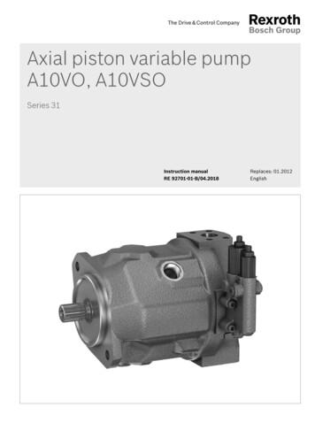
K3VG SeriesSwash Plate Type Axial Piston PumpGeneral DescriptionsThe K3VG Series Swash Plate Type Axial Piston Pumpsare designed to specifically satisfy the industrial opencircuit market where noise, efficiency, controllabilityand extended pump life are considered to be essential.K3VG Pumps are available in nominal displacementsranging from 3.84 to 34.2 in3/rev (63 to 560 cm3/rev)with various pressure, flow, and combination controloptions.Key features of K3VG Pumps include1. Reliable, High Pressure and Long Life Design- The K3VG Series Design is based on the K3V MobileSeries Pump where more than 700,000units havebeen supplied to the Construction Machinery Market.The K3VG pump incorporates high load bearings anda friction free contacting mechanism for the pistonshoes. This design has resulted in a pump with highreliability and long service life.2. Low Noise- The unique, compact and rigid housing constructionin addition to the semi-cylindrical pillow type swashplate and its anti-vibration supporting mechanism hassignificantly reduced noise levels.3. High Efficiency and High Self-Priming CapabilityFeaturesReliable, High Pressure, Long Life Modular Design.Low Noise and High Efficiency.Self-Compensating piston return mechanism.- K3VG Pumps encompass a spherical shaped valveplate design and improved hydraulic balancing whichprovide stable cylinder rotation, thus achieving highefficiency even in low-pressure, low-speed operatingconditions. The spherical shaped valve plate alsoenables a shortened radius of the cylinder ports, whichreduces the peripheral velocity and pressure-drop.Extensive Range of Highly Responsive Control Options.Auxiliary Gear Pump Option.Rated Pressure 350 Bar.Peak Pressure 400 Bar.This feature significantly improves the self-primingcapability of the pump.4. Extensive Range of Control Options- A large variety of hydromechanical and hydroelectriccontrol methods are available. Displacement, pressurecutoff, horsepower control, and various combinationsof these controls are available.High Continuous Power Rating.Fully Balanced Spherical Valve Plate.Infinite displacement control.Hydrostatically Balanced Swash Plate Support.5. Auxiliary Gear Pump- Various sizes of optional gear pumps can be provided.High Load Capacity Bearings.Therefore, no separate pump unit is necessary as acontrol pressure source or system medium-pressuresource and possible to attach high pressure gear pump.Hydraulic units can thus be made compact and moreeconomical.7
1Ordering CodeK3VG PUMPS1-1 Pump Options1234567891011121314K3VG180DT-1A0RSV1EH1-S1 4-1. K3VG Series PumpK3VG Series, Variable Displacement, Axial Piston, Open Loop Pump2. Pump SizeMaximum Displacementin3/revcm3/revNOT 1211.018017.128022.036034.2560------3. Hydraulic Fluid TypeMineral Oil-WWater GlycolPPolyol Ester4. Circuit Type1Open Circuit5. Attached Gear Pump0Without gear pump110 cm3 gear pump with built-in relief valve, set pressure 580psi215 cm3 gear pump with built-in relief valve, set pressure 580psi3Without gear pump, with assistant cover (only single pump)4-9,C-FHigh-pressure gear pump can be attachedAHigh-pressure gear pump can be attached-----------6. Mounting Bracket/Port Flange0Without bracket, With flangeFWith bracket, With flangeBWith bracket, Without flangeNWithout bracket, without flange7. Hydraulic Fluid TypeRClockwise RotationLCounter Clockwise Rotation8. Design CodeSDesign code9. Direction of MountingStandard (horizontal mounting)VVertical mounting12. Confluent block (Only tandem type)BlankSingle pump-0Without confluent block-SSide outlet type-RRear outlet type13. Auxiliary pump unit (Only tandem type)BlankWithout auxiliary pump unitWith auxiliary gear pump unit1(Only tandem type , clockwise type, and attached gear pump code 'A' )----14. Auxiliary pump unitBlankWithout resonator 4With resonator for 1,000-1,200 rpm 6With resonator for 1,500-1,800 rpm8
K3VG PUMPS1-2 Regulator Options1234567891011121314K3VG180DT-1A0RSV1EH1-S1 410. Pump Control OptionsPressure (horsepower) Control00No pressure (horsepower) control63112180280180DT280DTFlow ControlManual control0PNo pressure (horsepower) controlPositive flow control0NNo pressure (horsepower) controlNegative flow control0ENo pressure (horsepower) controlElectric flow control10Horsepower controlManual control1PHorsepower controlPositive flow control1NHorsepower controlNegative flow control1EHorsepower controlElectric flow control40Pressure constant (compensated)Manual controlLoad sense4LPressure constant (compensated)50Horsepower and pressure constantManual control5PHorsepower and pressure constantPositive flow control5NHorsepower and pressure constantNegative flow control5EHorsepower and pressure constantElectric flow control60*Pressure constant (compensated)Manual control6L*Pressure constant (compensated)Load sense70Horsepower and pressure constantManual control7PHorsepower and pressure constantPositive flow control7NHorsepower and pressure constantNegative flow control7EHorsepower and pressure constantElectric flow control7LHorsepower and pressure constantLoad sense11. Horsepower Set Code00No horsepower control (only for control option*)H#High setting rangeM#Medium setting rangeL#Low setting range* Non standard Options - Contact KPM9
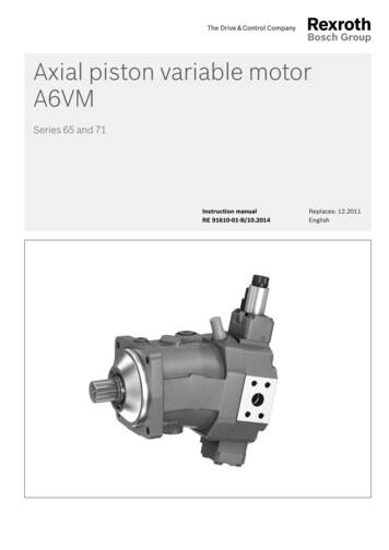
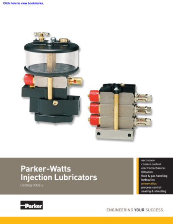
2Technical InformationK3VG PUMPS2-1 Technical DataFor applications outside the following parameters, please consult KPM.Hydraulic DataPressure FluidMineral oil, polyol ester and water glycol.Use a high quality, anti-wear, mineral based hydraulic fluid when the pressure exceeds 210bar. In applications where fire resistant fluids are required consult KPM.Fluid selectionAllowable temperature rangeViscosity [cSt]10006004002001008060402010-20 0(-4) (32)20(68)40(104)6080(140) (176)100(212)Temperature C ( F)Recommended range10
K3VG PUMPS2-1 Technical Data (cont)Filtration & ContaminationControlFiltrationThe most important means to prevent prematuredamage to the pump and associated equipment andto extend its working life, is to ensure that hydraulicfluid contamination control of the system is workingeffectively.Working Fluid TypesAnti-Wear Type Hydraulic fluidIt is generally recommended to use an anti-wearhydraulic fluid like mineral oil when the operatingpressure exceeds 210 bar.Fire-resistant FluidsSome kind of fire-resistant fluids require specialmaterials for seals, paint and metal finishing. PleaseThis begins by ensuring that at the time of installationconsult KPM and provide details of the particular fluidthat all piping, tanks etc. are rigorously cleaned in aspecification and the working conditions so that anysanitary way. Flushing should be provided using anspecial requirements can be ascertained.off line filtration system and after flushing the filterelements should be replaced.In general, fire-resistant fluids have a low viscosityindex and their viscosity also changes significantly withA full flow return line filter of 10 micron nominaloperating temperature and service life. For this reason,should be utilised to prevent contaminant ingress fromthe circuit should be provided with an adequatelythe external environment, a 5 to 10 micron filter withinsized cooler or forced cooling so that temperaturesthe tank’s breather is also recommended.can be stabilised. Due to the inherent water contentof some of these fluids the minimum allowable suctionSuggested AcceptableContamination Levelpressure will be higher than that of an equivalentmineral oil and so needs to be fully evaluated byKPM. The following table provides an overview of theprecautions and characteristics that can be expectedThe relationship between contamination level andwith these types of fluids.pump life is very difficult to predict as it depends onthe type and nature of the contaminant present in thesystem. Sand or Silica in particular, due to its abrasiveFluid TypeMineralOilPolyolEsterWaterGlycolnature, does significantly reduce the expected life ofParametera pump. Based on the precondition that there is noMaximumPressure emperatureRange F(C)68 - 140(20 - 60)68 - 140(20 - 60)50 - 122(10 - 50)100%50 - 100%20 - 80%significant presence of Silica type substances then aminimum Cleanliness level of -/18/15 ISO 4406 or SAEAS 4059E Table 1 Class 9 (NAS 1638 Class 9 ).CavitationsusceptibilityLife expectancycomparedto mineral oilrecommendedusable (higher density)11
K3VG PUMPS2-1 Technical Data (cont)Pump Start Up PrecautionsPump Case FillingBe sure to fill the pump casing with oil through the drain port, filling only the suction line with oil is totally insufficient. The pump contains bearings and high-speed sliding parts including pistons with shoes and sphericalbushes that need to be continuously lubricated. Part seizure or total premature failure will occur very quickly ifthis procedure is not rigidly followed.Piping & Circuit CheckingCheck to see that the piping and full hydraulic circuit is completed and that any gate valves etc. are open.Direction of RotationCheck to ensure that direction of rotation is correct and that the inlet and delivery lines are connected correctly.Start UpJog start the motor and check once more for correct rotation. Run the pump unloaded for a period to ensure thatall residual air within the system is released. Check for external leakage, abnormal noise and vibrations.Case Drain PressurePlease ensure, that the maximum steady state drain line pressure at the pump casing does not exceed 1 bar.(Maximum peak pressure 4 bar). A suitable drain line hose must be selected and return directly back to the tankand terminate below the oil level.Long Term Out of UsageIt is undesirable to leave the pump out of use for a long period e.g. a year or more. In such a situation it isrecommended that the pump is run for a short period on a more frequent basis even if it is just unloaded. Withregard to a pump held in storage then rotating the shaft on a frequent basis is sufficient. If the pump is left out formore than the suggested time it will require a service inspection.12
K3VG PUMPS2-2 SpecificationsFor applications outside of the following parameters please contact KPM.Pump 560)Displacementin(cm3/rev)Rated Pressure(1)psi(bar)5,075(350)Peak Pressure(2)psi(bar)5,800(400)Maximum SelfPriming imum (300)Consult bearing life charts for high horsepower applications. Please contact Kawasaki for application assistance.Maximum allowable safety relief valve setting.(3)Steady State Suction Pressure -1.45 psi (-2.95 in Hg), (-0.1 bar)(4)Minimum Recommended Boost Pressure at Suction Port 14.5 psi (29.52 in Hg), (1 bar)(5)Precautions must be taken when operating the K3VG280/DT at 1800 rpm.In order to prevent damage to the pump:(1)(2)SuctionPressureMaximumDisplacement 7.1psi( 0.5bar)280cc/rev 1.4psi( 0.1bar)250cc/rev-1.4psi(-0.1bar)232cc/rev13
K3VG PUMPS2-3 Functional Description of RegulatorsKey to Hydraulic Circuit AnnotationsAnnotationA , A1A2a , a1a2Main pump deliveryAuxiliary pump deliveryGauge port main pump deliveryGauge port auxiliary pump deliveryB , B1Main pump suctionB2Gear pump suctionbSuction gauge portDrDrainPiPilot pressurePcRemote pilot port, pressure compensatorPLLoad sense portPsvNote:DescriptionPressure assist portThe optional attached gear pump is recommended for all displacement control options. Hydraulic circuit diagramsillustrate the attached gear pump.14
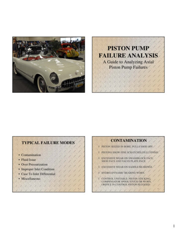
K3VG PUMPS2-3 Functional Description of Regulators (cont)0000 Stepless Manual Displacement ControlThe pump is supplied without a regulator.The discharge flow can be steplessly adjustedby manuall yturning adjustment screws on thepump. This adjustment provision is a standardfeature on all K3VG pumps providing a meansto limit the maximum and minimum displacement.Control CurvesHydraulic CircuitAaDischarge flow QRegulator CodeDischarge pressure PdbDr BRange of Flow Control 50-100%Discharge flow QaDischarge pressure PdPiDischarge flow QNegative Flow ControlbPilot pressure PiRange of Flow Control 100-2.5%Dr BAHorsepower ControlDischarge flow Q1P## Horsepower and Positive Flow ControlThis regulator combines the HorsepowerControl with Positive Flow Control. By addinga pilot signal to the Pi port the dischargeflow can be infinitely adjusted within therange of the pump. An increase in pilot signalwill result in an increase in flow, hence thePositive control.AHorsepower ControlaDischarge pressure PdPositive Flow ControlPiDischarge flow Q10## Horsepower Control1N## Horsepower and Negative Flow ControlIn response to a rise in delivery pressure, theswash plate tilting angle is decreased,restricting the input torque. This regulatorprevents excessive load against the primemover. By adding a pilot signal to the Piportthe discharge flow can be infinitely adjustedwith in the range of the pump. An increase inpilot signal will result in a decrease in flow,hence the Negative control.bPilot pressure PiRange of Flow Control 2.5-100%Discharge flow Qa1Discharge pressure PdElectric Flow ControlDischarge flow Qa240 barbElectric (Current) SignalDr B1Range of Flow Control 2.5-100%Horsepower Control,Pressure Cutoff ControlB2AaPiDischarge pressure PdNegative Flow ControlDischarge flow Q50## Horsepower and Pressure Cutoff5N## Horsepower, Pressure Cutoff andNegative Flow ControlThis regulator combines the HorsepowerControl with Pressure Cutoff Control. By addinga pilot signal to the Pi port the discharge flowcan be infinitely adjusted with in the range ofthe pump. An increase in pilot signa will resultin a decrease in flow, hence the Negative control.A2A1Horsepower ControlDischarge flow Q1E## Horsepower and Electric Flow ControlThis regulator combines the HorsepowerControl with Electric Flow Control.A proportional reducing valve is added to theregulator so the discharge flow can be infinitelyadjusted within the range of the pump. Anincrease in electric signal to the proportionalreducing valve will result in an increase in flow.This regulator requires an amplifier (refer topage9) to provide the electric signal.Dr BbPilot pressure PiRange of Flow Control 100-2.5%Dr B15
K3VG PUMPS2-3 Functional Description of Regulators (cont)5E## Horsepower, Pressure Cutoff andElectric Flow ControlThis regulator combines the Horsepower Control withPressure Cutoff and Electric Flow Control.A proportional reducing valve is added to the regulatorso the discharge flow can be infinitely adjusted withinthe range of the pump. An increase in electric signalto the proportional reducing valve will result in anincrease in flow. This regulator requires an amplifier(refer to page 9) to provide the electric signal.Discharge flow QHydraulic CircuitHorsepower Control,Pressure Cutoff ControlAaPiDischarge pressure PdDischarge flow QPositive Flow ControlDischarge flow Q5P## Horsepower, Pressure Cutoff andPositive Flow ControlThis regulator combines the Horsepower Control withPressure Cutoff Control. By adding a pilot signal tothe Pi port the discharge flow can be infinitelyadjusted within the range of he pump. An increase inpilot signal will result in an increase n flow, hencethe Positive control.Control CurvesbPilot pressure PiRange of Flow Control 2.5-100%Dr BHorsepower Control,Pressure Cutoff ControlA1 A 2a1Discharge pressure PdElectric Flow ControlDischarge flow QRegulator Codea240 barbElectric (Current) SignalRange of Flow Control 2.5-100%Dr B 1 B25L## Horse power and Load Sense ControlThis regulator combines Horsepower Control andLoad Sense Control.ADischarge flow QaPLDischarge pressure PdbDr BRange of Flow Control 2.5-100%A subplate can be added to the regulator that willaccommodate a proportional relief valve forvariable Pressure Cutoff Control.4L00 Load Sense ControlThis regulator controls the pump displacement tomatch the flow requirement as a function of loadpressure. In addition, there is a Pressure CutoffFunction incorporated into the regulator.AaDischarge flow QBy connecting the Pc port to a remote pressure control,variable pump pressure control can be achieved.PcTairDischarge pressure PdbDr BPLADischarge flow Q4000 Pressure Cutoff ControlThis regulator maintains a constant pressureregardless of the discharge flow. It is imperative thata safety relief valve is installed in the circuit.aDischarge pressure PdbRange of Flow Control 2.5-100%Dr B16
K3VG PUMPS2-3 Functional Description of Regulators (cont)By connecting the Pc port to a rem ote pressure control,variable pump pressure control can be achieved.A subplate can be added to the regulator that willaccommodate a proportional relief valve forvariable Pressure Cutoff Control.Hydraulic CircuitHorsepower Control,Pressure Cutoff ControlADischarge flow Q70## Horsepower and Pressure Cutoff7N## Horsepower, Pressure Cutoff andNegative Flow Control (with Remote PressureCutoff Capabili This regulator combines theHorsepower Control with Press Cutoff Control.By adding a pilot signal to the Piport the dischargeflow can be infinitely adjusted within the range ofthe pump. An increase in pilot signal will result in adecrease in flow, hence the Negative control.Control CurvesaPiDischarge pressure PdPCDischarge flow QRegulator CodebDischarge pressure PdDr BRange of Flow Control 100-2.5%By connecting the Pc port to aremote pressure control,variable pump pressure control can be achieved.A subplate can be added to the regulator that willaccommodate a proportional relief valve forvariable Pressure Cutoff Control.Horsepower Control,Pressure Cutoff ControlDischarge flow QAaPiDischarge pressure PdPositive Flow ControlPCDischarge flow Q7P## Horsepower, Pressure Cutoff and PositiveFlow Control(with Remote Pressure Cutoff Capability)This regulator combines the Horsepower Controlwith Pressur Cutoff Control. By adding a pilot signalto the Pi port the discharge flow can be infinitelyadjusted within the range of the pump. An increasein pilot signal will result in an increase in flow,hence the Positive control.bDr BPilot pressure PiRange of Flow Control 2.5-100%By connecting the Pc port to a remote pressure control,variable pump pressure control can be achieved.A subplate can be added to the regulator that willaccommodatea proportional relief valve forvariable Pressure Cutoff Control.Discharge flow QHorsepower Control,Pressure Cutoff ControlA1 A 2a1Discharge pressure PdPCElectric Flow Control40 barDischarge flow Q7E## Horsepower, Pressure Cutoff and Electric FlowControl (with Remote Pressure Cutoff Capability)This regulator combines the Horsepower Controlwith Pressure Cutoff and Electric Flow Control.A proportional reducing valve is added to theregulator so the discharge flow can be infinitelyadjusted within the range of the pump. An increasein electric signal to the proportional reducing valvewill result in an increase in flow. This regulatorrequires an amplifier (refer to page 9) provide theelectricsignal.a2bDr B1 B2Electric (Current) SignalRange of Flow Control 2.5-100%17
K3VG PUMPS2-4 Power Setting CodesHORSEPOWER SET CODES----------Standard Regulator at 1500 rpmMotor PowerK3VG Pump Frame Sizehp(kw)63112180280 180DT ample:Pump:K3VG112-10NR-10?Electric Motor:50hp at 1800 rpmHorsepower Set Code:M3Final Model Code:K3VG112-10NR-10M3Discharge flow QStandard Regulator at 1200 rpmMotor PowerK3VG Pump Frame Sizehp(kw)63112180280 180DT (149.1)HAMA250(186.4)H5300(223.7)H2Discharge pressure Pd-Standard Regulator at 1800 rpmMotor PowerK3VG Pump Frame Sizehp(kw)63112180280 180DT (298.3)H4*450(335.6)H2*----------*See precaution for operating K3VG280 and K3VG280DT at 1800 rpm on page 1.18
K3VG PUMPS2-4 Power Setting Codes (cont)HORSEPOWER ADJUSTMENT RANGEThe horsepower setting can be adjusted via external adjusting screws. The adjustment range of each horsepower control modeis given in the tables below.K3VG63Horsepowercontrol mode1200rpm hp (kW) 1500rpm hp (kW) 1800rpm hp (kW)HHighhorsepower23.5 - 35.9(17.5 - 26.8)29.5 - 45.3(22.0 - 33.8)35.6 - 54.7(26.6 - 40.8)MMediumhorsepower16.6 - 23.9(12.4 - 17.8)20.9 - 30.0(15.6 - 22.4)25.3 - 36.3(18.9 - 27.1)LLowhorsepower11.3 - 20.1(8.4 - 15.0)14.2 - 25.3(10.6 - 18.9)17.2 - 30.6(12.8 - 22.8)K3VG112Horsepowercontrol mode1200rpm hp (kW) 1500rpm hp (kW) 1800rpm hp (kW)HHighhorsepower39.3 - 33.1(29.3 - 49.3)49.6 - 83.2(37.0 - 62.1)59.8 - 100.5(44.6 - 75.0)MMediumhorsepower28.8 - 48.4(21.5 - 36.1)36.3 - 61.1(27.1 - 45.6)43.8 - 73.7(32.7 - 55.0)LLowhorsepower20.2 - 32.6(15.1 - 24.3)25.6 - 41.2(19.1 - 30.7)30.8 - 49.6(23.0 - 37.0)Horsepowercontrol mode1200rpm hp (kW) 1500rpm hp (kW) 1800rpm hp (kW)HHighhorsepower59.4 - 102.5(43.6 - 76.5)73.7 - 129.3(55.0 - 96.5)89.0 - 156.0(66.4 - 116.4)MMediumhorsepower46.6 - 79.8(34.8 - 59.5)58.8 - 100.5(43.9 - 75.0)71.0 - 121.3(53.0 - 90.5)LLowhorsepower31.8 - 48.4(23.7 - 36.1)40.1 - 61.1(29.9 - 45.6)48.4 - 73.7(36.1 - 55.0)K3VG280Horsepowercontrol modeDischarge flow QK3VG180Discharge pressure Pd1200rpm hp (kW) 1500rpm hp (kW) 1800rpm hp (kW)HHighhorsepower95.7 - 159.6(71.4 - 119.1)120.6 - 201.2(90.0 - 150.1)180.0 - 220.0(134.3 - 164.0)MMediumhorsepower71.6 - 120.6(53.4 - 90.0)90.2 - 152.1(67.3 - 113.5)120.0 - 180.0(89.5 - 134.3)LLowhorsepower49.7 - 79.7(37.1 - 59.5)62.7 - 100.5(46.8 - 75.0)80.0 - 125.0(59.7 - 93.3)K3VG180DTHorsepowercontrol mode1200rpm hp (kW) 1500rpm hp (kW) 1800rpm hp (kW)HHighhorsepower116.2 - 205.1(86.7 - 153.0)146.6 - 258.5(109.4 - 192.9)176.9 - 312.2(132.0 - 232.9)MMediumhorsepower93.4 - 143.0(69.7 - 106.7)117.8 - 180.3(87.9 - 134.5)142.1 - 217.7(106.0 - 162.4)LLowhorsepower63.7 - 96.9(47.5 - 72.3)80.3 - 122.1(59.9 - 91.1)96.9 - 147.4(72.3 - 110.0)K3VG280DTHorsepowercontrol mode1200rpm hp (kW) 1500rpm hp (kW) 1800rpm hp (kW)HHighhorsepower209.8 - 319.1(156.5 - 238.1)264.4 - 402.5(197.3 - 300.3)290.0 - 450.0(216.0 - 335.0)MMediumhorsepower145.8 - 254.3(108.8 - 189.7)183.9 - 320.6(137.2 - 239.2)240.0 - 310.0(179.0 - 231.0)LLowhorsepower99.5 - 170.1(74.2 - 126.9)125.3 - 214.5(93.5 - 160.0)160.0 - 245.0(119.0 - 183.0)19
K3VG PUMPS2-5 Performance DataK3VG63 - Overall Efficiency (%)Ratio of Displacement (q/q 6000% Volumetric Efficiency1.00 0.751,500rpm1,450(100)2,900(200)4,350(300)Delivery Pressure psi (bar)K3VG112 - Overall Efficiency (%)0.501001.0Ratio of Displacement (q/q max.)0.2590918090708960880.55086% Volumetric Efficiency1.00 300)Delivery Pressure psi (bar)20
K3VG PUMPS2-5 Performance Data (cont)K3VG180 and K3VG180DT - Overall Efficiency (%)0.500.25100Ratio of Displacement (q/q max.)1.0908070896050880.5% Volumetric Efficiency1.00 y Pressure psi (bar)K3VG280 and K3VG280DT - Overall Efficiency (%)0.501001.0Ratio of Displacement (q/q max.)0.25909180900.5898870865060% Volumetric Efficiency1.00 300)Delivery Pressure psi (bar)21
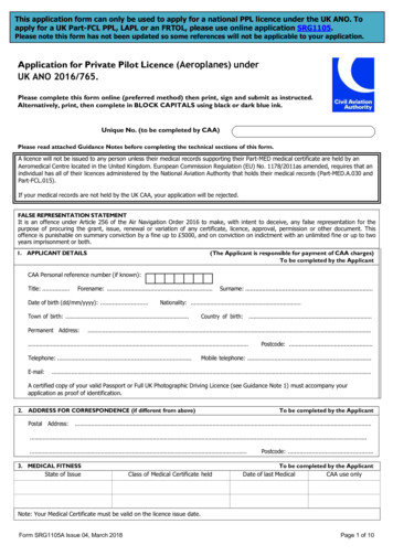
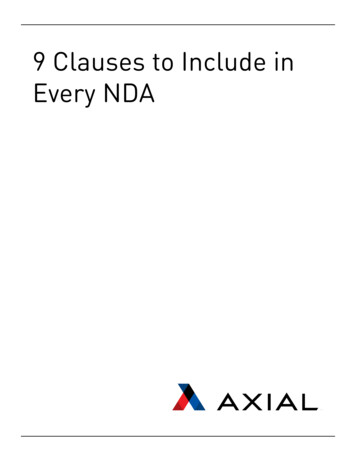
K3VG PUMPS2-5 Performance Data (cont)Displacement Control Curves100Positive Flow Control (*P**)9080355 14 psi100%Flow Rate (%)706050403020107 28 psi2.5%10050100150 200 250 300Pilot Pressure Pi (psi)350400450Negative Flow Control (*N**)1009080176 14 psi100%Flow Rate (%)7060504030488 28 psi15%201002.5%100200300400Pilot Pressure Pi (psi)500600Electric Flow Control (*E**)10090670 50 mA100%8070Flow Rate (%)K3VG63605040400mA16 5%30201002.5%100200300400500600Input Amperage i (mA)70080022
K3VG PUMPS2-5 Performance Data (cont)Displacement Control CurvesK3VG112100Positive Flow Control (*P**)9080356 14 psi100%Flow Rate (%)706050403020100 28 psi2.5%10050100150 200 250 300Pilot Pressure Pi (psi)350400450Negative Flow Control (*N**)1009080161 14 psi100%Flow Rate (%)7060504030481 28 psi15%201002.5%100200300400Pilot Pressure Pi (psi)500600Electric Flow Control (*E**)10090670 50 mA100%80Flow Rate (%)70605040400mA18 5%30201002
- Shield rotary parts, such as the motor and pump shaft, to avoid injury. - Stop operation immediately, and take proper measures when the abnormality such as . 00 No pressure (horsepower) control Manual control 0P No pressure (horsepower) control Positive flow control 0N No pressure (horsepower) control Negative flow control