Transcription
Explanation of Application Interface of AD/ADASvehicle motion controlAUTOSAR CP R20-11Document TitleExplanation of ApplicationInterface of AD/ADAS vehiclemotion controlDocument OwnerAUTOSARDocument ResponsibilityAUTOSARDocument Identification No988Document StatuspublishedPart of AUTOSAR StandardClassic PlatformPart of Standard ReleaseR20-11Document Change HistoryDateRelease2020-11-30R20-111 of 27Changed byAUTOSARReleaseManagementDescriptionInitial releaseDocument ID 988: AUTOSAR EXP AIADASAndVMC
Explanation of Application Interface of AD/ADASvehicle motion controlAUTOSAR CP R20-11DisclaimerThis work (specification and/or software implementation) and the material contained init, as released by AUTOSAR, is for the purpose of information only. AUTOSAR and thecompanies that have contributed to it shall not be liable for any use of the work.The material contained in this work is protected by copyright and other types of intellectual property rights. The commercial exploitation of the material contained in thiswork requires a license to such intellectual property rights.This work may be utilized or reproduced without any modification, in any form or byany means, for informational purposes only. For any other purpose, no part of the workmay be utilized or reproduced, in any form or by any means, without permission inwriting from the publisher.The work has been developed for automotive applications only. It has neither beendeveloped, nor tested for non-automotive applications.The word AUTOSAR and the AUTOSAR logo are registered trademarks.2 of 27Document ID 988: AUTOSAR EXP AIADASAndVMC
Explanation of Application Interface of AD/ADASvehicle motion controlAUTOSAR CP R20-11Table of Contents1 Introduction42 Description of Terms and Concepts52.12.2Axis System . . . . . . . . . . . . . . . . . . . . . . . . .Definitions . . . . . . . . . . . . . . . . . . . . . . . . . .2.2.1Centre of gravity of passenger car . . . . . . .2.2.2Polar coordinate system . . . . . . . . . . . . .2.2.3Vehicle acceleration/propulsive force direction2.2.4Cant direction . . . . . . . . . . . . . . . . . .2.2.5Steering wheel angle . . . . . . . . . . . . . .2.2.6Road Variables . . . . . . . . . . . . . . . . . .2.2.7Definition of the car surroundings . . . . . . .2.3Acronyms and Abbreviations . . . . . . . . . . . . . . . .2.4General remarks . . . . . . . . . . . . . . . . . . . . . .2.4.1Limitations . . . . . . . . . . . . . . . . . . . .2.4.2Sensor signals . . . . . . . . . . . . . . . . . .2.4.3Functional Safety . . . . . . . . . . . . . . . .2.4.4Assumption for ADAS application . . . . . . .56677889101213131313133 Related Documentation144 Architecture Overview154.1Functional Structure . . . .4.1.1ADAS Application4.1.2ADAS-MGR . . .4.1.3Vehicle-MGR . . .4.1.4Actuator . . . . . .4.2Scalability . . . . . . . . . .4.2.1ACC . . . . . . . .4.2.2AEB . . . . . . . .4.2.3LKA . . . . . . . .1517181920222223245 Description of the Chassis Domain Software Compositions and Components forVMC Architecture implementation255.13 of 27VMC Architecture as new SW-Components . . . . . . . . . . . . . . .25Document ID 988: AUTOSAR EXP AIADASAndVMC
Explanation of Application Interface of AD/ADASvehicle motion controlAUTOSAR CP R20-111IntroductionThis document explains the pattern for architecture of the Vehicle Motion Control Interface and its software components, as well as the design decisions that leads to anupdate of the Application Interface within Chassis Domain, as depicted in Figure 1.1.EnvironmentalmodelsScope: Vehicle control 3.1.2]ADAS-MGR(AMG)[3.1.3]Vehicle-MGR(VMG)Plant models[3.1.4]ActuatorsFigure 1.1: Scope of this documentThe scope of the vehicle control functions in this document is ”Implementation of ADASrequirements” only. The document will focus on a recommended signal cascadingarchitecture for ADAS function (particularly for ACC, AEB and LKA functions), for whichnew SW-Components will be created. For other chassis components, including vehiclestabilization controls (ABS/TCS, etc.), refer to [1, AUTOSAR EXP AIChassis].The purpose of defining the architecture (functional structure, I/F) in this document isto improve customer convenience in function development and development efficiencyin no-competitive areas by achieving the ease of function update change, the ease ofdesign and verification and the ease of mutual understanding.4 of 27Document ID 988: AUTOSAR EXP AIADASAndVMC
Explanation of Application Interface of AD/ADASvehicle motion controlAUTOSAR CP R20-112Description of Terms and ConceptsThis document refers to the formulation of unified Application Interfaces of the DomainChassis in the frame of a specific pattern implementation of Advanced Driver Assistance Systems (ADAS) with a specific Vehicle Motion Control interface. The results ofthe Domain Chassis shall be aligned with the other domains, e.g. Body, Powertrain,Occupant and Pedestrian Safety. The Application Interface Table represents a goodbasis for this alignment and detection of conflicts.2.1Axis SystemThe standard coordinate system used by the Chassis Domain refers to the InternationalStandard [2, ISO 8855]. Whether a fixed geometry point (e.g. near to the averageCentre of Gravity (CoG) of all variants of a vehicle type) is used as a reference pointfor basic Centre of Gravity has to be decided on project level.5 of 27Document ID 988: AUTOSAR EXP AIADASAndVMC
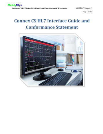
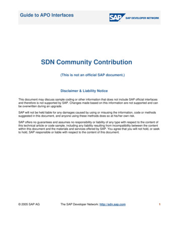
Explanation of Application Interface of AD/ADASvehicle motion controlAUTOSAR CP R20-112.22.2.1DefinitionsCentre of gravity of passenger carThe car’s chassis-fixed coordinate system’s origin lies in the middle of the Front Axle(FA) see Figure 2.1. The car’s Centre of gravity is defined as the origin of a chassisfree coordinate-system that is positioned relative to the FA co-ordinate system. Theorientations of both these co-ordinate systems’ axes are defined as follows:With the car moving forward: x is positive to the front of the car y is positive to the left of the car z is positive to the top of the car Roll is positive in a left-hand bend, when the car body tips to the right-hand side Pitch is positive when a car is braking and the car body tips forward Yaw is positive in a left-hand bendFigure 2.1: Definition of a car’s Centre of Gravity (CoG)6 of 27Document ID 988: AUTOSAR EXP AIADASAndVMC
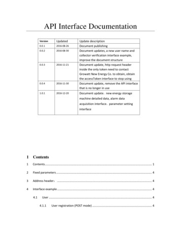
Explanation of Application Interface of AD/ADASvehicle motion controlAUTOSAR CP R20-112.2.2Polar coordinate systemThe polar coordinate system is defined as follows: With the vehicle moving forward, φ is positive in the counter clockwise directionr φTop viewFigure 2.2: Polar coordinates system2.2.3Vehicle acceleration/propulsive force direction Longitudinal Lateral(Same as Cartesian coordinate system)Figure 2.3: Plus, or minus sign of vehicle acceleration/propulsive forceDeceleration is expressed as negative value.7 of 27Document ID 988: AUTOSAR EXP AIADASAndVMC
Explanation of Application Interface of AD/ADASvehicle motion controlAUTOSAR CP R20-112.2.4Cant direction(Same as roll) CantFigure 2.4: Plus, or minus sign of cant2.2.5Steering wheel angle -(Same as yaw)Figure 2.5: Plus, or minus sign of steering wheel angle8 of 27Document ID 988: AUTOSAR EXP AIADASAndVMC
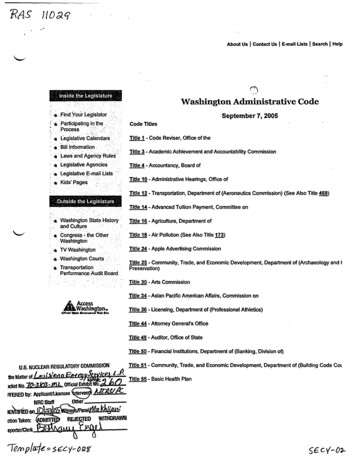
Explanation of Application Interface of AD/ADASvehicle motion controlAUTOSAR CP R20-112.2.6Road VariablesRoad curvature Yaw angle OffsetLeft edge ofthe laneCentre ofthe laneRight edgeof the laneFigure 2.6: Variables of road9 of 27Document ID 988: AUTOSAR EXP AIADASAndVMC
Explanation of Application Interface of AD/ADASvehicle motion controlAUTOSAR CP R20-112.2.7Definition of the car surroundingsFigure 2.7: Definition of car surrounding for ACC10 of 27Document ID 988: AUTOSAR EXP AIADASAndVMC
Explanation of Application Interface of AD/ADASvehicle motion controlAUTOSAR CP R20-11Figure 2.8: Definition of predicted course11 of 27Document ID 988: AUTOSAR EXP AIADASAndVMC
Explanation of Application Interface of AD/ADASvehicle motion controlAUTOSAR CP R20-112.3Acronyms and AbbreviationsPlease also refer to [3, AUTOSAR TR Glossary] for explanation of commonly usedterms and abbreviations within AUTOSAR.Abbreviation / ARSCSRSSMSTRSWSW-CTCSVFBVGRVLCVMVMCVSSYRC12 of 27Description:Antilock Braking SystemAdaptive Cruise ControlAccelerationActuatorAdvance Driver Assistance SystemAutonomous Emergency BrakingBrake AssistBrakeBasic Rear Wheel SteeringBasic Steering Torque SuperpositionBasic Steering Angle SuperpositionCornering Brake ControlCentre of GravityDriver Assistance SystemRegulation of the Drag TorqueElectronic Brake Force DistributionElectronic Control UnitElectronic Parking BrakeElectronic Stability ControlFront AxleHill Decent ControlHill Hold ControlHuman Machine InterfaceHardwareInterfaceLane Keep AssistManagerNoise, Vibration, HarshnessOriginal Equipment ManufacturerPowertrainRear AxleRoll Stability ControlSituation RecognitionStand Still Manager/ManagementSteeringSoftwareSoftware ComponentTraction Control SystemVirtual Function BusVariable Gear RatioVehicle Longitudinal ControlVehicle ModelVehicle Motion ControlVehicle State SensorsYaw Rate ControlDocument ID 988: AUTOSAR EXP AIADASAndVMC
Explanation of Application Interface of AD/ADASvehicle motion controlAUTOSAR CP R20-112.4General remarks2.4.1LimitationsThis Explanatory is set to status "‘draft"’ in R20-11. Detail I/Fs are not defined.The logical architectures proposed do not restrict the development or products of companies or organizations participating in AUTOSAR.2.4.2Sensor signalsIn ADAS, signals of different processing levels are handled for I/F definition. Raw signal: Raw sensor data without pre-processing Pre-processed signal: Pre-processed sensor data. Abstraction of sensor hardware Fused signal: Several sensor signals are processed to generate a fused signalRaw signals (raw data) should not be used as standard I/F because they are hardwaredependent.2.4.3Functional SafetyMost ADAS domain signals are considered as relevant to safety. It is assumed that inthis document, reliable methods of communication are available. No specification ofcommunication methods is provided in this document.Dynamic design and safety concepts are not considered in this document. In orderto prove that the discussed use cases are safety compliant (in accordance with thedefinition of [4, ISO 26262], [5, ISO 21448], etc.), studies across all applicable domainswill be necessary, and these must be performed at the project level.2.4.4Assumption for ADAS applicationThis document applies the architecture to three ADAS applications (ACC, AEB, andLKA) as a first version.Assumptions for these three applications are shown below: ACC: Does not include the operating range of 30 km/h or less. AEB: Does not include restarting after stopping. LKA: Does not include the operating range of 65 km/h or less.13 of 27Document ID 988: AUTOSAR EXP AIADASAndVMC
Explanation of Application Interface of AD/ADASvehicle motion controlAUTOSAR CP R20-113Related Documentation[6, ”JASPAR Standards Document: ST-AVI-1”] is also used as a reference for thisdocument.[1] Explanation of Application Interfaces of the Chassis DomainAUTOSAR EXP AIChassis[2] ISO 8855:2011, Road vehicles – Vehicle dynamics and road-holding ability – Vocabularyhttp://www.iso.org[3] GlossaryAUTOSAR TR Glossary[4] ISO 26262:2018 (all parts) – Road vehicles – Functional Safetyhttp://www.iso.org[5] ISO/PAS 21448:2019 – Road vehicles – Safety of the intended functionalityhttp://www.iso.org[6] JASPAR Standards Document: ST-AVI-1 – AD/ADAS Vehicle Control InterfaceSpecification Ver. 1.0https://www.jaspar.jp/en14 of 27Document ID 988: AUTOSAR EXP AIADASAndVMC
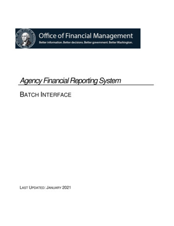
Explanation of Application Interface of AD/ADASvehicle motion controlAUTOSAR CP R20-114Architecture Overview4.1Functional StructureThis document defines the vehicle control functions for ADAS in four layers. (Thickbordered frame in Figure 4.1).1. ADAS Application2. ADAS-MGR3. Vehicle-MGR4. Domain Actuators ( related Domain Sensors)A MGR layer is set for each ADAS and actuator system and the I/F between each layeris standardized in order to loosen the relationship between the ADAS applications andactuators, and reduce the effect that adding or changing functions for one element hason another. For example, the effect of adding or changing a function for the ADASsystem can be absorbed in the ADAS-MGR layer. ADAS-MGR can communicate withVehicle-MGR via the standardized I/F, which reduces the effects on subsequent functions. Also, it can make it easier to add and/or change actuators without drasticallyaffecting the Vehicle-MGR; the reduction in interdependency can also simplify functional safety analysis of the system.The whole ADAS architecture consists of the four layers above, ADAS sensor layer andfusion layer. Examples of ADAS sensors include vision sensors (e.g., camera), radar,and LiDAR. ADAS sensors monitor the vehicle surroundings and send raw signals (rawdata) or pre-processed signals to the fusion layer. The fusion layer fuses signals fromeach sensor to recognize surrounding conditions. The recognition results are sent tothe ADAS application layer.This document does not cover ADAS sensors and fusion layers that do not have adirect I/F with vehicle control, as described in Figure 1.1. As a general rule, wherepossible, interaction between the actuators is avoided in the VMC architecture.15 of 27Document ID 988: AUTOSAR EXP AIADASAndVMC
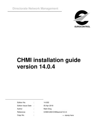
Explanation of Application Interface of AD/ADASvehicle motion controlAUTOSAR CP R20-11TermADAS SensorsFusionPLNPLaNVMCVehicle Motion e State Sensors[3.1.1] ADAS ApplicationPLN1PLN2[3.1.2] ADAS-MGR (AMG)VMC1VMC2[3.1.3] Vehicle-MGR (VMG)ACL1BRK1STR1PowertrainACL2 STR2BRK2 VSS2[3.1.4] ActuatorBrakeSteeringSensorsFigure 4.1: Functional architecture of vehicle controlTable 4.1 shows the main I/Fs between TR2VSS2ExplanationAntilock Braking SystemI/F from ADAS application layer to ADAS-MGR layerI/F from ADAS-MGR layer to ADAS application layerI/F from ADAS-MGR layer to Vehicle-MGR layerI/F from Vehicle-MGR layer to ADAS-MGR layerI/F from Vehicle-MGR layer to Actuator layer (Powertrain)I/F from Actuator layer (Powertrain) to Vehicle-MGR layerI/F from Vehicle-MGR layer to Actuator layer (Brake)I/F from Actuator layer (Brake) to Vehicle-MGR layerI/F from Vehicle-MGR layer to Actuator layer (Steering)I/F from Actuator layer (Steering) to Vehicle-MGR layerI/F from Actuator layer (Sensor) to Vehicle-MGR layerTable 4.1: Main I/Fs between layers16 of 27Document ID 988: AUTOSAR EXP AIADASAndVMC
Explanation of Application Interface of AD/ADASvehicle motion controlAUTOSAR CP R20-114.1.1ADAS ApplicationThe functions of the ADAS application are shown in Figure 4.2 and Table 4.2.Driver SW inputRecognition sensor info.ACC State Management(ON/OFF/STANDBY)AEB State Management(ON/OFF)LKA State ManagementACC FailureDiagnosisAEB FailureDiagnosisLKA FailureDiagnosisACCAccelerationReq.Calculationto equirementCalculationfrom ADAS-MGRFigure 4.2: ADAS application functionsFunctionBased on a driver assist request via a user interface, such as a switch and/or recognition sensorinformation, each ADAS application requests as individual kinematic plan (longitudinal acceleration/deceleration, etc.) for securing safety and/or comfort.Each ADAS application performs failure detection and internal state management by itself.Each ADAS application acts based on status of the ADAS application selected by ADAS-MGR.*The external stop function is undecided and needs further discussion.Each ADAS application act based on the external stop request.Table 4.2: Functional description of ADAS Application17 of 27Document ID 988: AUTOSAR EXP AIADASAndVMC
Explanation of Application Interface of AD/ADASvehicle motion controlAUTOSAR CP R20-114.1.2ADAS-MGRfrom ADAS ApplicationArbitrate ADAS applicationrequirement・Prioritize and select requestLongitudinal acceleration・Generate target longitudinalacceleration・Complement target longitudinalacceleration・Determine upper and lowe limittorque for steering assistaccording to each applicationto Vehicle-MGRto ADAS ApplicationAcknowledgement/notification of ADAS applicationstatus・Judgement of driveroverride・Discrimination amongADAS applications*This part is undecidedand needs furtherdiscussion.ADAS applicationexternal stop judgment・Driver operation stopjudgment・Actuator system stopjudgment・Vehicle sensor stopjudgmentfrom Vehicle-MGRFigure 4.3: ADAS-MGR functionsFunctionADAS-MGR arbitrates individual requested kinematic plans from each ADAS application and integrates ADAS kinematic plan for securing safety and/or comfort.ADAS-MGR requests Vehicle-MGR for arbitration mode of the requested kinematic plan (includingpreparations for the kinematic plan) and driver operations.ADAS-MGR performs the driver override judgment based on the vehicle state, and informs eachADAS application of the results of arbitration of the kinematic plan request and the selected ADASapplication.*The external stop function is undecided and needs further discussion.ADAS-MGR judge witch ADAS application cancel by witch level based on vehicle status andinform to each ADAS application *discussion need to be continued.Table 4.3: Functional description of ADAS-MGR18 of 27Document ID 988: AUTOSAR EXP AIADASAndVMC
Explanation of Application Interface of AD/ADASvehicle motion controlAUTOSAR CP R20-114.1.3Vehicle-MGRfrom ADAS-MGRto ADAS-MGRChange dimension forACT target valueRealizing ADASapplicationrequirements・Driving acceleration・Driving feedbackcontrollerNotification actuatorsystem availability forADAS request・Generate vehiclespeed for display・Braking acceleration・Yaw rate・Braking feedbackcontroller・Steering feedbackcontrollerProcessing andnormalization ofvehicle sensor info.Actuator statusinterpretation・PT, BRK, STR failure・Stability controlVehicle sensor statusinterpretationTorque Distribution PTand BRKto each actuatorfrom each actuatorfrom each vehicle SensorFigure 4.4: Vehicle-MGR functionsFunctionVehicle-MGR calculates/distributes the motion request (driving, braking, steering) for the actuatorsystem in order to realize the kinematic plan requested by ADAS-MGR.Vehicle-MGR requests each actuator for the arbitration mode between the motion request anddriver operation request.Vehicle-MGR informs ADAS-MGR of the vehicle status based on each actuator system status andmomentum sensing information that have been processed if needed.Table 4.4: Functional description of Vehicle-MGR19 of 27Document ID 988: AUTOSAR EXP AIADASAndVMC
Explanation of Application Interface of AD/ADASvehicle motion controlAUTOSAR CP R20-114.1.4ActuatorFunctionActuator system realizes vehicle motion request (driving, braking, steering) based on driver operation.Actuator system realizes vehicle motion request (driving, braking, steering) from Vehicle-MGR.Each actuator system realizes vehicle motion request based on arbitration request from VehicleMGR.Actuator system notifies Vehicle-MGR of ON/OFF information about driver operation (acceleratorpedal, brake pedal, holding steering wheel).Actuator system notifies Vehicle-MGR of status of actuator system (driving, braking, steering).Actuator system notifies Vehicle-MGR of information about vehicle momentum.Table 4.5: Functional description of actuator systemThe actuator system consists of following sub-systems.a) Powertrainfrom Vehicle-MGRAcceleratorpedalArbitration of drivingtorque/forceto Vehicle-MGRRealization of drivingforcePT capabilityinformation and faildiagnosticFigure 4.5: Powertrain system functionsb) Brakefrom Vehicle-MGRBrake pedalArbitration of brakingtorqueto Vehicle-MGRRealization of brakingforceBrake capabilityinformation and faildiagnosticFigure 4.6: Brake system functions20 of 27Document ID 988: AUTOSAR EXP AIADASAndVMC
Explanation of Application Interface of AD/ADASvehicle motion controlAUTOSAR CP R20-11c) Steeringfrom Vehicle-MGRSteering wheelArbitration of steeringto Vehicle-MGRRealization of steeringangleSTR capabilityinformation and faildiagnosticFigure 4.7: Steering system functions21 of 27Document ID 988: AUTOSAR EXP AIADASAndVMC
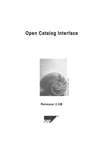
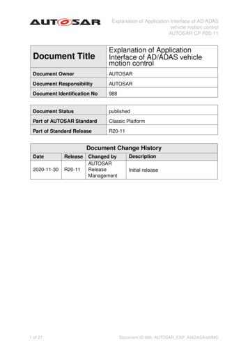
Explanation of Application Interface of AD/ADASvehicle motion controlAUTOSAR CP R20-114.2ScalabilityUse cases of applying this architecture to ACC, AEB, and LKA are shown below. TheI/F or functions to be used can be selected to enable the scalability of this architectureeven when combining multiple ADAS applications or adding applications in the future.4.2.1ACCFigure 4.8 shows a use case that uses ACC only.[3.1.1] ADAS ApplicationPLN1ACCPLN2[3.1.2] ADAS-MGR (AMG)VMC1VMC2[3.1.3] Vehicle-MGR (VMG)ACL1BRK1STR1PowertrainACL2 STR2BRK2 VSS2[3.1.4] ActuatorBrakeSteeringSensors【legend】I/FI/FUsed I/Ffunc.Used functionNot used I/Ffunc.Not usedfunctionFigure 4.8: Use case: ACC22 of 27Document ID 988: AUTOSAR EXP AIADASAndVMC
Explanation of Application Interface of AD/ADASvehicle motion controlAUTOSAR CP R20-114.2.2AEBFigure 4.9 shows a use case that uses AEB only.[3.1.1] ADAS ApplicationPLN1AEBPLN2[3.1.2] ADAS-MGR (AMG)VMC1VMC2[3.1.3] Vehicle-MGR (VMG)ACL1BRK1STR1PowertrainACL2 STR2BRK2 VSS2[3.1.4] ActuatorBrakeSteeringSensors【legend】I/FI/FUsed I/Ffunc.Used functionNot used I/Ffunc.Not usedfunctionFigure 4.9: Use case: AEB23 of 27Document ID 988: AUTOSAR EXP AIADASAndVMC
Explanation of Application Interface of AD/ADASvehicle motion controlAUTOSAR CP R20-114.2.3LKAFigure 4.10 shows a use case that uses LKA only.[3.1.1] ADAS ApplicationPLN1LKAPLN2[3.1.2] ADAS-MGR (AMG)VMC1VMC2[3.1.3] Vehicle-MGR (VMG)ACL1BRK1STR1PowertrainACL2 STR2BRK2 VSS2[3.1.4] ActuatorBrakeSteeringSensors【legend】I/FI/FUsed I/Ffunc.Used functionNot used I/Ffunc.Not usedfunctionFigure 4.10: Use case: LKA24 of 27Document ID 988: AUTOSAR EXP AIADASAndVMC
Explanation of Application Interface of AD/ADASvehicle motion controlAUTOSAR CP R20-1155.1Description of the Chassis Domain SoftwareCompositions and Components for VMCArchitecture implementationVMC Architecture as new SW-ComponentsThe implementation of ADAS functionalities within the Chassis Domain was alreadyintroduced through the introduction of Application Interfaces (Figure 5.1 and Figure5.2).Figure 5.1: Chassis Domain Overview25 of 27Document ID 988: AUTOSAR EXP AIADASAndVMC
Explanation of Application Interface of AD/ADASvehicle motion controlAUTOSAR CP R20-11Figure 5.2: Example of a Chassis Domain StructureIn addition, as mentioned in the example of Chapter 5.1 of [1, AUTOSAR EXP AIChassis], several structures can be discussed to arrange the globalarchitecture of the functional components, as in following example (Figure 5.3):Figure 5.3: Example of a dedicated structure of existing AI Chassis domain componentsfor ADAS purpose26 of 27Document ID 988: AUTOSAR EXP AIADASAndVMC
Explanation of Application Interface of AD/ADASvehicle motion controlAUTOSAR CP R20-11The understanding of the VMC architecture should also be interpreted as anotherChassis Domain structure, for which each layer of the VMC architecture can or cannotbe composed of other existing Chassis Domain nBrakeSteeringSensorsFigure 5.4: New Example of VMC Structure (left) compared to Example of Chassis Domain Structure (right)The scope of this document is limited only to the definition of the interfaces betweenthe SW-Components that comprise the VMC architecture: ADAS, AMG, VMG and (existing) Actuators/Sensors. Therefore, the content of each components is left up toproject convenience and the way the existing SW-Components is integrated in VMCarchitecture is not defined in this document. However, in case the VMC architectureis implemented along the existing SW-Components in AI Chassis domain, it will beneeded to: limit the information flow from currently existing Chassis Domain SW-C ports consider arbitration gates that will be defined through new SW-Components.27 of 27Document ID 988: AUTOSAR EXP AIADASAndVMC
Figure 1.1: Scope of this document The scope of the vehicle control functions in this document is "Implementation of ADAS requirements" only. The document will focus on a recommended signal cascading architecture for ADAS function (particularly for ACC, AEB and LKA functions), for which new SW-Components will be created.