Transcription
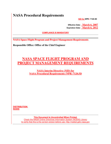
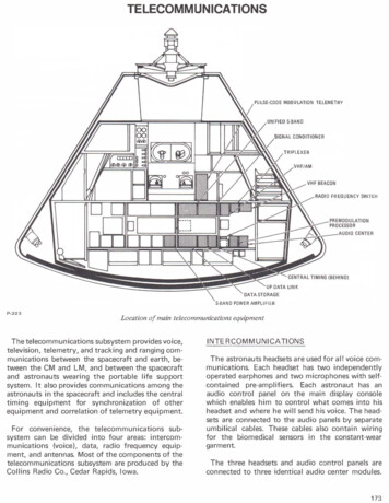
TELECOMMUNICATIONSPULSE-COOE MODULATION TELEMETRYUNIFIED S-BANDNAL CONDITIONERTRIPLEXERVHF/AM0FREQUENCY SWITCHP DATA LINKS-BAND POWER AMPLIFIERP-223Location of main telecommunications equipmentThe telecommunications subsystem provides voice,television, telemetry, and tracking and ranging com munications between the spacecraft and earth, be tween the CM and LM, and between the spacecraftand astronauts wearing the portable life supportsystem. It also provides communications among theastronauts in the spacecraft and includes the centraltimingequipmentforsynchronizationof otherequipment and correlation of telemetry equipment.Forconvenience,the telecommunications sub system can be divided into four areas: intercom munications (voice), data, radio frequency equip ment, and antennas. Most of the components of thetelecommunications subsystem are produced by theCollins Radio Co., Cedar Rapids, Iowa.INTERCOMMUNICATIONSThe astronauts headsets are used for all voice com munications. Each headset has two independentlyoperated earphones and two microphones with self containedpre-amplifiers.Each astronaut has anaudio control panel on the main display consolewhich enables him to control what comes into hisheadset and where he will send his voice. The head sets are connected to the audio panels by separateumbilical cables. These cables also contain wiringfor the biomedical sensors in the constant-weargarment.The three headsets and audio control panels areconnected to three identical audio center modules.173
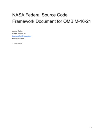
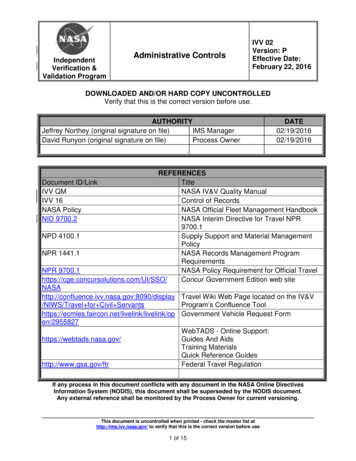
The audio center is the assimilation and distributionpoint for all spacecraft voice signals. The audiosignals can be routed from the center to the appro priate transmitter or receiver, the launch controlcenter (for pre-launch checkout), the recoveryforces intercom, or voice tape recorders.limited amount of audio signals can be stored ontape. During recovery, the VHF/AM and recoveryintercom equipment are used to maintain contactwith ground stations and with frogmen.Two methods of voice transmission and receptionare possible: the VHF/AM transmitter-receiver andthe S-band transmitter and receiver. Transmissionis controlled by either the push-to-talk switch locatedin the astronaut's umbilical cable or the voice operated relay circuitry during recovery operations.The push-to-talk switch also can be used like a tele graph key for emergency transmission.The spacecraft structure and subsystems containsensors which gather data on their status and per formance. Biomedical, TV, and timing data also isgathered. These various forms of data are assimilatedinto the data system, processed, and then trans mitted to the ground. Some data from the opera tional systems, and some voice communications,may be stored for later transmission or for recoveryafter landing. Stored data can be transmitted to theground simultaneously with voice or real-time data.DATAThe VHF/AM equipment is used for voice com munications with the manned space flight networkduring launch, ascent, and near-earth phases of amission. The S-band equipment is used during bothnear-earth and deep-space phases of a mission. Whencommunications with earth are not possible, aSignals from some of the instrumentation sensorsare fed into signal conditioning (converting) equip ment. These signals, and others which are alreadyconditioned or don't need to be, are then sent to aVHF OMNIVOICE2,600 N. ML2-GC OMNIIOOWN VOICE38,000 N. MLUP-DATABACKUP VOICE &EMERGENCY KEY220,000 N M LTELEMETER(LOW BIT RATE)200,000 N. MLTELEMETER22,000 N. ML(HIGH BIT RATE)P2-GC HIGH-GAINUP-DATA, UP-VOICEWIDE BEAMDOWN VOICE,MEDIUM BEAMTELEMETRYNARROW BEAMDEEP SPACE BLINDAREATV NEAREARTH &DEEP SPACELUNAR OPERATIONS:VH.F: VOICE, CM-LMRENDEZVOUS RADAR/TRANSPONDER, CM-LMHIGH-GAIN ANTENNAOPERATIONAL (2500).1A4.68.020.030.04050RANGE FROM EARTH'S SURFACE IN NAUTICAL MILES (TH OUSANDS)P-224174CSM communication ranges
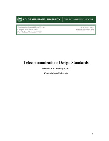
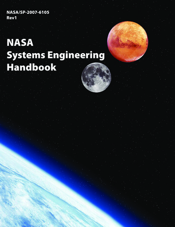
data distribution panel, which routes them to CMdisplays and to pulse-code modulation telemetryequipment. The latter combines them into a singlesignal and sends it to the premodulation processor.The premodulation processor is the assimilation,integration, and distribution center for nearly allforms of spacecraft data. It accepts signals fromtelemetry, data storage,TV, central timing, andaudio center equipment. It modulates, mixes, andswitchesthesesignalsto the appropriate trans mitter or to data storage.ANTENNASThere are nine antennas on the command andservice modules, not counting the rendezvous radarantenna which is an integral part of the rendezvousradar transponder.These antennas can be divided into four groups:VHF, S-band, recovery, and beacon. The two VHFantennas (called scimitars because of their shape)are omni-directional and are mounted 1 80 degreesapart on the service module. There are five S-bandantennas, one mounted at the bottom of the serviceVoice and data command signals from the groundreceived over the S-band receiver also are suppliedto the processor, which routes them to the audiocenter equipment or the up-data link (ground com mand) system. Up-data is of three types: guidanceand navigation data for updating the CM computer,timing data for updating the central timing equip ment, and real-time commands. The commandsgive the ground limited control over certain space craft telecommunications functions.module and four located 90 degrees apart aroundthe command module. The high-gain antenna isstowed within the SLA until the transposition anddocking maneuver, when it is deployed so that it isat right angles to the module. It can be steeredthrough a gimbal system and is the principal antennafor deep-space communications. The four S-bandantennas on the command module are mountedflush with the surface of the module and are usedfor S-band communications during near-earth phasesof mission, as well as for a backup in deep space.The two VHF recovery antennas are located in theRADIO FREQUENCY EQUIPMENTforward compartment of the command module, andThe radio frequency equipment is the means bywhichvoiceinformation,telemetrydata,andare deployed automatically shortly after the mainparachutes.Oneof these antennas also is con ranging and tracking information are transmittednected to the VHF recovery beacon.AM transceivers (transmitter-receiver) in one unit,EQUIPMENTand received. The equipment consists of two VHFIthe unified S-band equipment (primary and sec ondary transponders and an FM transmitter), pri mary and secondary S-band power amplifiers (inone unit), a VHF beacon, an X-band transponder(forrendezvous radar),processor.and theAll communication and data system units are inthecommandmodulelowerequipmentmounted to coldplates for cooling.bay,premodulationThe equipment provides for voice transfer be lWO SCIMITAR VHFFOUR S·BANO OMNIDIRECTIONALOMNIDIRECTIONAL ANTENNASANTENNAS(180 DEGREES APART)tween the CM and the ground, between the CMandLM,astronauts,betweentheand betweenCMtheandCMextravehicularandrecoveryforces. Telemetry can be transferred between theCM and the ground, from the LM to the CM andSLAthen to the ground, and from extravehicular astro nauts to the CM and then to the ground. Ranginginformation consists of pseudo-r·andom noise andTRANSPONDER ANTENNA0the CM and back to the ground and X-band radarVHFbeaconequipmentemitsa2-secondsignal every 5 seconds for Iine-of-sight direction - lWOVHF BLADE- RECOVERYANTENNASSTEERABLE S-BANOHIGH-GAIN ANTENNAfinding to aid recovery forces in locating the CMafter landing. --.,signals from the LM to the CM and back to the LM.The RENDEZVOUS RADARdouble-doppler ranging signals from the ground toP-225Location of antennas175
(Collins Radio Co., Cedar Rapids,Audio CenterIowa)-Center weighs 7.9 pounds and is 4. 7 t is a 28-volt,withthree20-wattidentical headsetfor each crewman.It providescommunication among astronauts, between astro between the spacecraft data-gathering equipmentand the S-band RF electronics. It accomplishessignal modulation and demodulation, signal mix ing, and the proper switching of signals so that thecorrect intelligence corresponding to a given modeof operation is transmitted.nauts and launch pad personnel, and post-landingrecovery frogmen, recording of audio signals inconjunction with tape recording equipment, andrelaying of audio signals.all1 0-pound unit provides time correlation ofspacecraftgeneratesminute,time-sensitiveand missionday,alsohour,inbinary-coded decimal format for onboard recordingandtransmissiontothe Manned Space FlightNetwork. It is normally synchronized to a con tinuously generated signal from the guidance andnavigation computer. If the signal is lost, backup isprovidedby synchronizingtoa self-containedsource. The unit contains two power supplies elbourne,EquipmentFla.)- ThisEach is supplied from a differentpower source and through separate circuit breakers.The two power supplies provide parallel 6-volt deoutputs, either one of which is sufficient to powerThe 1 1 5/200 volt, 3-phase, 400-Hertz unit has twomodes of operation: high-bit rate of 5 1 .2 kilobitsper second (normal mode) and low-bit rate of 1 . 6kilobits per second. It receives and samples italbiomedical,information,operation,output for transmission to earth.S-BandF l u s h - M ountedAntennas(AmecomDivision of Litton Systems, Inc.)- Four antennas,each 3.5 inches long and 2.1 inches in diameterwith3. 1 2-inchdiametermountingring,2.5 pounds. They are omnidirectional right-handpolarized Helix antennas in a loaded cavity. TheStorage Equipment (Leach Corp., Azusa,Calif. ) - This 40-pound unit is 22 by 9.5 by 6 in ches and operates from 1 1 5-volt, 3-phase, 400Hertz and 28-volt de power. Tape is one-inch, 1 4track Mylar. It operates at three speeds: 3. 75, 1 5,and 120 inches per second. While being playedback, the tape speed is selected automatically toProvide an apparent 5 1 . 2 KBPS PCM data. It playsin a single direction, but a rewind mode is provid ed. It stores data and voice information duringpowered phases of mission and during periods oflost communications and plays them back later.Digital Ranging Generator (RCA)-This generator,used with the VHF/AM transmitter-receiver, sup plements the lunar module rendezvous radar sys tem by providing distance-to LM information inthe CM. It has solid-state circuitry and is housed ina machined-aluminum case 4 by 6 by 8.5 inches. Itweighs 6- 1 / 2 pounds.Premodulation Processor (Collins) - It is of solidstate design and modular construction and hasredundant circuitry. It weighs 1 4.5 pounds and is28 volts de. It provides the interface connectionaremounted on the command module. Each weighsData4.7 by 6 by 10.5 inches. It requires 1 2.5 watts atandscientific data, and converts it to a single serialthe entire unit.176unitweighs 42.1 pounds and is 1 3 by 7 by 1 4 inches.Central Timing Equipment (General Time Corp.)ThisP u lse-CodeP-226Technican at Radiation, Inc., checks outpulse-code modulation telemetry unit
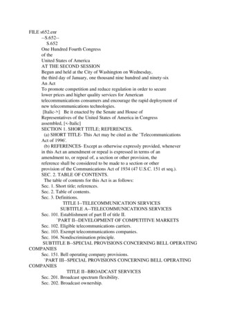
astronaut selects the antenna he will use. Theytransmit and receive all S-band signals duringnear-earth operation and are backup for thehigh-gain antenna in deep space.2-Gigahertz High-Gain Antenna (Textron's DalmoVictor Company, Belmont, Calif.} -An array offour 31-inch diameter parabolas clustered aroundan 11-inch-square wide-beam horn. It weighs 94pounds and is 65 by 64 by 33.78 inches. It ismounted to the aft bulkhead of the servicemodule and is used for deep-space communica tions with the unified S-band equipment. Actualdeployment takes place during transposition anddocking phase of the mission when the spacecraftlunar adapter panels are opened. After deploy ment, the antenna is capable of automatically ormanually tracking the R F signal within the travellimits of its gimbaling system. It has three modesof operation: wide, medium, and narrow beam.NO.3NO.5S-Band Power Amplifier (Collins} -This traveling wave-tube power amplifier is housed in a sealedand pressurized case 5. 75 by 5.56 by 22.26 inchesand weighs 32 pounds. It has two independentamplifiers, either of which can amplify outputs ofe i t h e r the phase-modulated or frequency modulated unified S-band transmitters. It operateson 3-phase, 115/200 volt, 400 Hertz power. Itstwo power outputs are 2.8 and 11.2 watts. Theamplifier increases the low-power output of theunified S-band equipment to high power.Signal Conditioner (North American Rockwell'sA u t o ne t i c s D i vis i o n }- T h i s 4 5 - p ou n d ,1191-cubic-inch electronics package is in the lowerequipment bay. It requires 28 volts de andconsumes about 35 watts. It transforms signalsfrom sensors and transducers to basic instrumenta tion analog (coded measurements) voltage level.Signals are then distributed to telemetry andcommand module displays.TV Camera (RCA Astro Electronics for CM} -The85-cubic-inch camera weighs 4.5 pounds andrequires 6.75 watts at 28 volts de. It has a 1-inchvidicon tube. Its frame rate is 10 frames persecond with 320 lines per frame. Its wide anglelens is 160 degrees. The telephoto lens is 90degrees. It can be operated at three I ocationswithin the command module. It transmits toreceiving stations on earth via the unified S-bandequipment, and the signals are processed there tobe compatible with commercial television. (TheFEEOHORNS10 OFFSETP·227High-gain antenna constrnctionTV camera to be used on the lunar surface,supplied by Westinghouse Electric's AerospaceDivision, Baltimore, is stowed in the LM and ispart of its equipment.}Unified S-Band Equipment (Motorola, Inc., MilitaryElectronics Division, Scottsdale, Ariz.} - Twophase-locked transponders and one frequency modulated transmitter are housed in single, gasket sealed, machined aluminum case, 9.5 by 6 by21 inches. The unit weighs 32 pounds, operatesfrom 400 Hertz power, with RF output of 300milliwatts. It is used for voice communications,tracking and ranging, transmission of pulse-code modulated data and television, and reception ofup data. It is the normal communications link tothe spacecraft from the earth.177
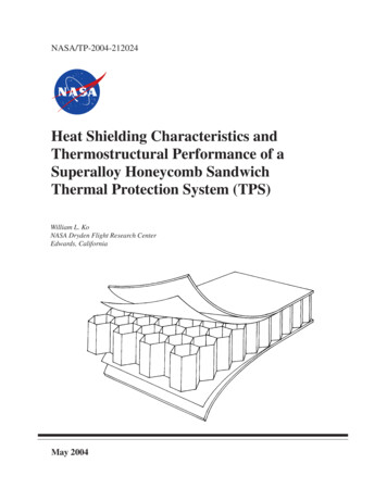
U p - D a taL i nk Equipment (Motorola)-This21-pound device is 6 by 18.3 by 9.6 inches. Itreceives, verifies, and distributes digital updatinginformation sent to the spacecraft from theManned Space Flight Network at various timesthroughout the mission to update or change themodes of the telecommunications systems. Datais received by the S-band receiver and routed tothe up-data link.VHF/AM Transmitter-Receiver(RCA DefenseElectronic Products Communications SystemDivision, Camden, N.J.)- It is one case housingdual transmitters and receivers for simplex orduplex operation. The enclosure contains 1 1subassemblies, two coaxial relays, and two band pass filters mounted within a three-piece hermeti cally sealed case. Powered from 28 volts de, the5-watt ( RF output) unit weighs 13- 1/2 poundsand is 6 by 4. 7 by 12 inches. It is used for voicecommunication between the command moduleand earth during near-earth and recovery phases ofmission, for voice and data communicationbetween the command module and lunar moduie,and between the command module and astronautsengaged in extravehicular activity.VHF Omnidirectional Antennas (North AmericanRockwell's Columbus Division) -Two scimitarantennas are located on the service module 180degrees apart. Each is 19 by 9 inches and 1-inchthick and weighs 12.5 pounds. They are stainlesssteel with a fiberglass skin and a covering ofTeflon. They provide for two-way voice com munication between the command module andearth, between the command module and thelunar module, between the command module andextravehicular activity personnel, and for voiceand biomedical telemetry from the lunar moduleto the command module.VHF Recovery Beacon (Collins) -The beacon is asolid-state, 1000-Hertz tone-modulated AM trans mitter. It transmits for two seconds followed bythree seconds of no transmission. It weighs 2. 7pounds and is 4 by 4 by 6.75 inches. The 3-wattunit is powered by 28 volts de. It emits signals toprovide line-of-sight direction finding for recoveryforces.VHFRecovery Antennas (North AmericanRockwell's Los Angeles Division) -Two antennasare mounted on the forward compartment of the178REEFING LINE CUTIERP-228Recovery beaconcommand module. No. 1 is connected to VHFrecovery beacon. No. 2 is used during recoverywith VHF/ AM transmitter-receiver for voice com munication or transmission of line-of-sight beaconsignal. Each antenna is a quarter-wave groundplane antenna with a 10-inch radiating element,and weighs 3 pounds. They are not extended until8 seconds after the main chutes are deployed.VHF Triplexer (Rantec, Inc.) -It weighs 1.7pounds and is 3.93 by 3.33 by 4.6 inches. Itallows transmission and reception of two RFfrequencies via one antenna.DETAILED DESCRIPTIONINTERCOMMUNICATION EQUIPMENTThe audio center equipment provides the necessaryaudio signal amplification and switching for com munication among the three astronauts, communi cation between one or more astronauts and extra vehicular personnel, recording of audio signals inconjunction with tape recording equipment, andrelaying of audio signals. The audio center equip ment consists of three electrically identical setsof circuitry which provide parallel selection, isola tion, gain control, and amplification of all voice
.-----VHF------.VHF NO.2VHF NO. 1RECOVERYVHFVHFRECOVERY BEACONCOMMANDER'SUMBILICAlCM PILOT[EARPHONE. I' Jj!! !Q.T L,---1r: ., UMBILICALIIj- !Q.T K ---- ICROPHONELMPILOTUMBILICALEARPHONELEGEND INTERCOM EQUIPMENT. ANTENNA EQUIPMENT '-', DATA EQUIPMENT RfEQUIPMENTmONs:::. J. :J -----: - -WEM. :.::.:.::.:.:.:.:'"'DISPLAYJ--- SIGNAL----CON TRO LTelecommunications subsystem--
communications. Each set of circuitry containsan isolation pad, diode switch, and gain controlfor each receiver input and an intercom channel;an isolation pad and diode switch for each trans mitter modulation output and an intercom channel;an earphone amplifier and a microphone amplifier;and voice-operated relay circuitry with externallycontrolled sensitivity.The equipment operates with three remote con trol panels to form three audio stations, each pro viding an astronaut with independent control. Eachstation can accommodate a second astronaut foremergency operation. Any or all of the transmitterscan be turned on at each station. A "hot mike"enables continuous intercrew communication. Whena transmitter is turned on, the correspondingreceiver also is turned on. Sidetone is provided inall transmit modes.Audio signals are provided to and from the VHF/AM transmitter-receiver equipment, unified S-band,and the intercom bus. The intercom bus is commonto all three stations and provides for the hardlinecable communications among crewmen and with thelaunch control center and recovery force swimmers.Voice communication is controlled by the VHF/AM, S-band, and intercom switches on the audiocontrol panels. Each of these switches has threepositions: T/R (transmission and reception of voicesignals), RCV (reception only), and Off. The Powerswitch of each station energizes the earphoneamplifier to permit monitoring. The operation of themicrophone amplifier in each station is controlledby the voice-operated relay keying circuit or thepush-to-talk button on the communications cableor rotation controller. The voice operated relaycircuit is energized by the "Vox" position of theMode switch on each audio control panel. Whenenergized, this circuit will enable both the inter com and accessed transmitter keying circuits. The" Intercom/PTT" position permits activation ofthe VHF/AM, and S-band voice transmission circuitsby the push-to-talk key while the intercom is oncontinuously. The "PTT" position permits manualactivation of the intercom or intercom and trans mitter keying circuits by depression of the "I'COM"or "XM IT" side of the communication cable switch,respective Iy.Five potentiometer controls are provided on eachaudio control panel: The "Vox Sens" control isHIGHGAINS·BAND OMNIDIRECTIONAL- -·,.11-.,·[l.lli]LMVOICEEVA2106.4 MCVOICE2287.5 MCINTERCOM VOICE TODATA STORAGES-BAND DOWN VOICEAUDIOPREMODULATION PROCESSORS-BAND UP VOICECENTERRELAYP-230Audio system relationship to other systems180TRI PLEXER
signals are conditioned at or near the sensor by in PERSONAL COMMUNICATIONSASSEMBLYdividual conditioners located throughout the space craft. Other signals are fed to the signal conditioningCONSTANT-WEARequipment, a single electronics package located inGARMENTthe lower equipment bay.conditioningequipmentIn addition, the signalalsosupplies5-voltdeexcitation power to some sensors. The equipmentcan be turned on or off by the crew, but that is theonly control they have over instrumentation equip rementsflightarequalificationthosenormallyrequired for a routing mission and include threecategories: in-flight management of the spacecraft,mission evaluation and systems performance, andP-231pre-flight checkout. The operational instrumentationsensors and transducers measure pressure, tempera Communications cableture, flow, rate, quantity, angular position, current,used to adjust the sensitivity of the voice-operatedrelay circuitry, determining the amplitude of thevoltage, frequency, RF power, and "on-off" typeevents.voice signal necessary to trigger the keying circuit.The"S-band,VHF/AM, and Intercom" volumecontrols are used to control the signal levels fromthe respective units to the earphone amplifier. The"Master Volume" controls the level of the ampli fied signal going to the earphones.recoveryinterphonement. Most of these measurements wi II be pulse-codemodulated along with the operational measurementsand transmitted to the ground. Other flight qualifi The intercom bus connects to ground supportequipment,Flight qualification measurements depend on mis sion objectives and the state of hardware develop (swimmerum cation measurements will be stored for post-flightanalysis.bilical), and the premodulation processor which inturn routes the signal to the data storage equipmentThe central tlmtng equipment provides precisionfor recording.square wave timing pulses of several frequencies toDATA EQUIPMENTerates and stores the day, hour, minute, and secondof mission elapse and time in binary-coded decimalInstrumentationequipmentcorrelate all time-sensitive functions. It also gen consistsofvarioustypes of sensors and transducers which monitorenvironmental and operational systems, and experi mental equipment. The output of these sensors andtransducers are conditioned into signals suitable forthe spacecraft displays and for telemetry to theground.Various digital signals, including event information,guidance and navigation data, and a time signal fromthe central timing equipment, also are telemeteredto the ground.Many of the signals emanating from the instru mentation sensors are in forms of levels which areunsuitable for use by the displays or telemetryequipment. Signal conditioners are used to convertthese to forms and levels that can be used. Someformat for transmission to the ground.In primary or normal operation, the commandmodule computer provides a 1 ,024-kiloHertz syncpulse to the central timing equipment. This auto matically synchronizes the central timing equipmentwith the computer. If this pulse fails, the centraltiming equipment automatically switches to thesecondary mode of operation with no time lapseand operates using its own crystal oscillator. Thecentraltimingequipmentcontainstwopowersupplies for redundancy. Each is supplied from adifferent power source and through separate circuitbreakers.The timing signals generated by the central timingequipment go to the following equipment:181
Pulse codemodulationequipmentFor synchronization of an in ternal clock, frame synchroni zation, and time-correlation ofpulse-code modulated dataPremodulationprocessorFor S-band emergencytransmissionElectrical powersubsysteminvertersFor synchronization of 400cycle ac powerDigital eventtimerPulse for digital clockEnvironmentalcontrolsubsystemTo discharge water from astro nauts suits (1 pulse every 10minutes)Scientific dataequipmentFor time-correlation of dataThe signal conditioning equipment is a hermeticallysealed unit contained in a single electronics packagein the lower equipment bay. Its function is toaccept and process a variety of inputs from varioussystems within the spacecraft and produce analogsignals compatible with pulse-code modulation ordisplays and to provide excitation voltages tosome of the instrumentation sensors and trans ducers. The package contains de differential ampli fier assemblies, de differential bridge amplifierassemblies, an ac to de converter assembly, deactive attenuator assemblies, and redundant powersupplies. The signal conditioning equipment con tains an error detection circuit which automaticallyswitches to the redundant power supply if the pri mary power supply voltages go out of tolerance. Aswitch on the main display console allows the crewkeyVHF OMNI·OIRECTIONALRIGHTLEFTVHFRECOVERYNO.2 :· · 1024 K C .:S·BAND OMNI-DIRECTIONALVHFRECOVERYBEACON ------ - - ---- ELMPCMEVATIME CODECPSNON-U:ST A R !:T-!ST O P!SY N C--f . . . , RETURNDIGITAL SERIAL. . .DIGITALPCMPCM EVAVOICE/BIOMEOREALTIMEDATA- f. -,-- J BIT RATE,TO ZEROPRECONDITIONEO ANALOG1---'-'Ac:.:.NA:.:.::.:L Dc GVOICE/BIOMED512 M (PLAY BACKNORMAL)(REAL·TIMEAUXILIARYLMPCMCM lCCLM &EVAVOICEI · I IJ!i ll liillilli, '----fltU I OUOOiiVOI(f Ill\CIUf\1()0(1 IIU I. IUCo-Mt PCM PULSE-CODE MODULATED. . "(.P-232''"'Data system relationship to other systems182. .,. o.u,.
to switch between either power supply. The equip ment requires 28-volt de power and consumes35 watts maximum with a full complement ofmodules.The pulse-code modulation telemetry equipmentconverts data inputs from various sources through out the spacecraft into one serial digital signal. Thissingle-output signal is routed to the premodulationprocessor for transmission to the ground or to datastorage equipment. The pulse-code modulated tele metry equipment is located in the lower equipmentbay. Incoming signals are of three general types:high-level analog, parallel digital, and serial digital.Two modes of operation are possible: the high (normal) bit-rate mode of 51.2 kilobits per secondand the low- (reduced) bit-rate mode of 1.6 kilobitsper second.The analog multiplexer can accommodate 365 high level analog inputs in the high-bit rate mode. Theseanalog signals are gated through the multiplexer, thehigh-speed gates, and are then fed into the coder. Inthe coder, the 0- to 5-volt analog signal is convertedto an 8-bit binary digital representation of thesample value. This 8-bit word is parallel-transferredinto the digital multiplexer where it is combinedwith 38 external 8-bit digital parallel inputs to formthe output in non-return-to zero format.This digital parallel information is transferred intothe output register where it is combined with thedigital serial input, and then transferred serially intothe data transfer buffer. From here the informationis passed on to the premodulation processor forpreparation for transmission.line communications before liftoff.The TV video signal from the premodu lation pro cessor also may be routed to the S-band FM trans mitter and its associated power amplifier for trans mission to the ground for reception of TV duringflight.The data storage equipment stores data for delayedplayback or recovery with the spacecraft. Informa tion is recorded during powered flight phases andwhen out of communications and is played back(dumped) when over selected S-band stations. Theequipment, located in the lower equipment bay,has tape speeds of 3.75, 15, and 120 inches persecond. The tape speed is selected automaticallybased on the data rate. The tape has fourteenparallel tracks: four CM pulse code modulateddigital data, one digital clock, one LM pcm data,one CM-LM voice, three scientific data, and fourspare.The flight qualification recorder is a 14-trackmagnetic tape recorder used to record certain flightqualification measurements during critical phasesof the mission. This data will be used for post-flightanalysis only; it cannot be played back or transmittedduring flight. It will be activated during the ascentand entry phases of the mission and during servicepropulsion engine firings. Flight qualification datais recorded in analog form. Two recording tracks(one record head in each of two record-head stacks)7.00-- ,The pulse-code modulation telemetry equipmentreceives 512-kiloHertz and 1-Hertz timing signalsfrom the central timing equipment. If this sourcefails, its programmer uses an internal timing ref erence. The timing source being used is telemetered.Two calibration voltages are also telemetered as aconfidence check of the operation of the telemetryequipment.Television equipment consists of a small, portableTV camera that can be hand-held or mounted inthree locations in the command module. The camerais connected to a 12-foot cable for use throughoutthe CM. The camera is controlled by a switch on thecamera handle and an automatic light control switchon the back. Power required by the camera is 6.75watts at 28 volts de. The composite video signal issent from the camera to the premodulation processorwhere it is then sent to the SM umbilical for hard-WIOE-ANG LELENSApollo television cameraP-233183
are used for reference and time code recording. Toaccomplish this, an elapsed time code generator isused to modulate a narrow-band voltage-controlledoscillation. The output of the voltage-controlledoscillator is then mixed with the output of a501-kiloHertz reference oscillator. This compositesignal is presented to each of the two record headsthrou
center equipment or the up-data link (ground com mand) system. Up-data is of three types: guidance and navigation data for updating the CM computer, timing data for updating the central timing equip ment, and real-time commands. The commands give the ground limited control over certain space craft telecommunications functions.