Transcription
ADATTM– AES3 – S/P-DIF DIGITAL AUDIO FORMATAND SAMPLING RATE CONVERTERV2MUTEC part no. 8015-100Professional A/V TechnologyGermany
SAFETY INSTRUCTIONSGeneral instructionsTo reduce the risk of fire or electrical shock, do not expose this appliance to rain or moisture, directsunlight or excessive heat from sources such as radiators or spotlights. No user serviceable parts are inside. Repair and maintenance must be carried out by qualified personnel authorized by MUTEC GmbH!The unit has been designed for operation in a standard domestic environment. Do NOT expose the unitand its accessories to rain, moisture, direct sunlight or excessive heat produced by such heat sources asradiators or spotlights! The free flow of air inside and around the unit must always be ensured.Initial operationPrior to the initial operation of the unit, the appliance, its accessories and packaging must beinspected for any signs of physical damage that may have occurred during transit. If the unit hasbeen damaged mechanically or if liquids have been spilled inside the enclosure, the appliance maynot be connected to the mains or must be disconnected from the mains immediately! If the unit isdamaged, please do NOT return it to MUTEC GmbH, but notify your dealer and the shipping company immediately, otherwise claims for damage or replacement may not be granted.If the device is left in a low-temperature environment for a long time and then is moved to a roomtemperature environment, condensation may occur on the inside and the exterior. To avoid shortcircuits and flashovers, be sure to wait one or two hours before putting the device into operation.Power supplyThe device contains a self-adapting wide-range power supply supporting the majority of global standard line voltages within a range of 90 250 V, with no need for making adjustments. Make sure thatyour line-voltage source provides a supply voltage within the specified range. In addition, make surethat the device is properly grounded via the local electric installation.Please use the enclosed power cord (see packaging) to connect the unit to the mains. Switch theunit off before you attempt to connect it to the mains. Connect the power cord to the unit, thento a standard 3-pin mains outlet. To draw the power cord, never pull on the cable but on the mainsplug!C A U T I O NR I S KO FELECTRICAL SHOCK!!This symbol, a flash of lightning inside a triangle, alertsyou to the presence of uninsulated dangerous voltageinside the enclosure - voltage that may be sufficient toconstitute a risk of shock.!This symbol, an exclamation mark inside a triangle,alerts you to important operating or safety instructionsin this manual.Declaration of ConformityWe herewith confirm that the product complies with the EuropeanCommission’s standards on electromagnetic compatibility.Interference emission:Resistance to interference:EN 50081-1, 1992EN 50082-1, 1992Presupposed as operation condition is that all clock outputs are connected with high-quality and good shielded BNC 75 ohms cable.The unit must be grounded during operation!For information on the power-inlet wiring, refer to the »Wiring of connectors« section in theappendix. Disconnect the device from the mains when not using it for an extended period!WARRANTY REGULATIONS§1 WarrantyMUTEC GmbH warrants the flawless performance of this product to the original buyer for a period of two (2) years from the date of purchase. If any failure occurs withinthe specified warranty period that is caused by defects in material and/or workmanship, MUTEC GmbH shall either repair or replace the product free of charge within 90days. The purchaser is not entitled to claim an inspection of the device free of charge during the warranty period. If the warranty claim proves to be justified, the productwill be returned freight prepaid by MUTEC GmbH within Germany. Outside Germany, the product will be returned with the additional international freight charges payableby the customer. Warranty claims other than those indicated above are expressly excluded.§2 Warranty transferabilityThis warranty is extended exclusively to the original buyer who bought the product from a MUTEC GmbH specialized dealer or distributor, and is not transferable to anyonewho may subsequently purchase this product. No other person (retail dealer, distributor, etc.) shall be entitled to give any warranty promise on behalf of MUTEC GmbH.§3 Waranty regulationsThe return of the completed registration card, or online registration on one of the websites specified below, is a condition of warranty. Failing to register the device beforereturning it for repair will void the extended warranty.The serial number on the returned device must match the one stated on the registration card or entered during online registration. Otherwise, the device will bereturned to the sender at the sender’s expense.Any returned device must be accompanied by a detailed error description and a copy of the original sales receipt issued by a MUTEC dealer or distributor.The device must be returned free of shipping expenses and in the original package, if possible; otherwise, the sender has to provide comparably protective packaging.The sender is fully responsible for any damage or loss of the product when shipping it to MUTEC GmbH.§4 Limitation of warrantyDamages caused by the following conditions are not covered by this warranty:Damages caused by every kind of normal wear and tear (e.g. displays, LEDs, potentiometers, faders, switches, buttons, connecting elements, printed labels, coverglasses, cover prints, and similar parts).Functional failure of the product caused by improper installation (please observe CMOS components handling instructions!), neglect or misuse ofthe product, e.g. failure to operate the unit in compliance with the instructions given in the user or service manuals.Damage caused by any form of external mechanical impact or modification.Damage caused by the user’s failure to connect and operate the unit in compliance with local safety regulations.Damage caused by force majeure (fire, explosion, flood, lightning, war, vandalism, etc.).Consequential damages or defects in products from other manufacturers as well as any costs resulting from a loss of production.Repairs carried out by personnel which is not authorized from MUTEC GmbH will void the warranty. Adaptations and modifications to the device made with regard tonational, technical, or safety regulations in a country or of the customer do not constitute a warranty claim and should be set with MUTEC GmbH in advance.§5 RepairsTo obtain warranty service, the buyer must call or write to MUTEC GmbH before returning the unit. All inquiries must be accompanied by a description of the problem andthe original buyer’s invoice. Devices shipped to MUTEC GmbH for repair without prior notice will be returned to the sender at the sender’s expense. In case of a functionalfailure please contact:MUTEC Gesellschaft fuer Systementwicklung und Komponentenvertrieb mbHSiekeweg 6/8 12309 Berlin Germany Fon 030-746880-0 Fax 030-746880-99 Tecsupport@MUTEC-net.com www.MUTEC-net.comJET and Jitter Elimination Technology are trademarks of TC Applied Technologies Ltd. The JET technology is used under sublicense from TC Applied Technologies Ltd., and is the intellectual property ofSonopsis Ltd. Applicable patents include WO2004088845.MUTEC GmbH assumes no liability for any incorrect information given in this manual. Please note thatall software/hardware product names are registered trademarks of their respective owners. No part ofthis manual may be reproduced, copied or converted to a machine-readable form or electronical mediawithout a written permission of MUTEC GmbH. We reserve the right to change or improve our productswithout prior notice. MUTEC GmbH 2012
CONTENTINTRODUCTIONGeneral Function Description. . . . . . . . . . . . . . . . . . 7MC-4 Features . . . . . . . . . . . . . . . . . . . . . . . . . . 7MC-4 Applications. . . . . . . . . . . . . . . . . . . . . . . . 7Peripheral MUTEC Products. . . . . . . . . . . . . . . . . . . 8CONTROL ELEMENTS AND TERMINALSMC-4 Front Panel. . . . . . . . . . . . . . . . . . . . . . . . .9MC-4 Rear Panel . . . . . . . . . . . . . . . . . . . . . . . . . 9INSTALLATIONContent of the Box. . . . . . . . . . . . . . . . . . . . . . . .11Placing the device . . . . . . . . . . . . . . . . . . . . . . . . 11Wiring the optical ADATTM, AES/EBU and S/P-DIF Interfaces. . 11Wiring the Word Clock Interfaces. . . . . . . . . . . . . . . .11GENERAL OPERATIONSelecting Function Menus and setting Functions . . . . . . .13Steps of Operation. . . . . . . . . . . . . . . . . . . . . . . .13OPERATING THE MC-4MODE AUDIO IN REFERENCE Menus. . . . . . . . . . . . .15General Operation Procedure . . . . . . . . . . . . . . . . . .15Unidirectional Format Conversions . . . . . . . . . . . . . . .16Unidirectional Format and Sampling Rate Conversions . . . .17Bidirectional Format Conversions. . . . . . . . . . . . . . . .18Bidirectional Format and Sampling Rate Conversions . . . . .19X-SRC Mode. . . . . . . . . . . . . . . . . . . . . . . . . . . .20STATUS . . . . . . . . . . . . . . . . . . . . . . . . . . . . . .21CLOCK IN . . . . . . . . . . . . . . . . . . . . . . . . . . . . . 21APPENDIXPin Assignment of the Connectors . . . . . . . . . . . . . . . 23Technical Data . . . . . . . . . . . . . . . . . . . . . . . . . . 24
\B E D I E N E L E M E N T E INTRODUCTIONThank you very much for purchasing the MC-4, Digital Audio Format andSampling Rate Converter, from MUTEC!General Function DescriptionThe MC-4 is an extremely flexible, high-performance digital audio format and sampling rate converter for ADATTM, AES3 and S/P-DIF. All digitalaudio signals can be processed with 8 channels and sampling rates up to192.0kHz, whereas unidirectional and bidirectional conversion modes areavailable. Based on latest FPGA designs, the MC-4 achieves levels of performance regarding its signal quality, unique flexibility, clocking features andthe 16 channel sampling rate conversion engine (SRC), which are outstanding in today’s industry!Various operation modes enable the use of the MC-4 in many studio setups. Generally, incoming digital audio signals are converted to all threeaudio formats simultaneously, with or without SRC functionality. The SRCengine can be locked to Word Clock, AES11 and any digital audio input inboth, unidirectional and bidirectional operation modes.Furthermore, the MC-4 offers an internal, low-jitter clock base with highaccuracy to which the SRCs can be locked to, if no external reference isavailable. This enables to run the MC-4 in set-ups where no separate masterclock is available. Furthermore, in this operation mode the MC-4‘s WordClock output supplies a low-jitter reference clock signal which is of samehigh accuracy as the internal clock base. This can be used e.g. as masterclock reference for the whole studio.This all makes MC-4 for sure a unique and the most flexible digital audiomultichannel converter in a ½ 19“ case currently available in the market!MC-4 FeaturesADATTM, AES/EBU and S/P-DIF interfaces in one box.Bidirectional format and sampling rate conversionsfrom 32.0 kHz to 192.0 kHz.Converts standalone and bidirectionally with different sampling rates: X-SRCSupports ADATTM, SMUX2 and SMUX4 standards.Signal improvement through low-jitter clock recovery.AES11, Grade 1, internal reference clock.Low-jitter Word Clock output can be used as master clock reference.Runs standalone without needing an external clock source.16 channel SRC engine for bidirectional conversions.Extremely flexible synchronization options.Continuous signal supply in absence of the reference audio or clock signalSeparate AES11 reference clock input.Simultaneous conversions to all output formats.Easy configurable.User‘s settings will be stored after switching-off.Rack space saving ½ 19“ housing allowing for mounting two devices inone rack unit.Built-in international power supply.The grey boxes contain supplementaryinformationen for the correspondingsections in the text columns. The content ofthe individual box refers to the descriptionin the text column beside the box.Boxes which contain a triangle withan exclamation mark inside shouldbe read carefully! These includeadditional information which are of majorimportance for the functional descriptionsin the text column.!!Register your MUTEC Productfor Warranty and Support!We ask you to be so kind to registeryour MUTEC product through our websiteimmediately after purchasing. This ensuresfull warranty services over a period of twoyears after purchasing the product. Moreover, for all registered products we offer toour customers technical support. We alsowill inform you about product updates andnew products which may of interest for you(on voluntary base, of course).Please regsiter your product at:www.MUTEC-net.com SERVICES, MUTEC Product RegistrationMC-4 ApplicationsInterconnection of consumer and professional digital audio devices.ADATTM SMUX2 /4, AES3 and S/P-DIF format and sampling rateconversions.Integration of non-synchronizable devices into digital studioenvironments.Clock recovery and digital audio signal regeneration.Realtime bidirectional signal transfer between send/returns of digitalmixing consoles and effect processors.Unidirectional or bidirectional interconnection of computer-based soundcards with professional digital audio equipment.ADATTM signal splitting and distribution.Usable within small studio set-ups up to broadcast installations. 887
INTRODUCTION\\\\\\\\\\\\ Peripheral MUTEC ProductsReference Clocks and Master Clocks for Synchronization:iCLOCK iCLOCKdpiCLOCK and iCLOCKdp are synchronizable, high-precision clockgenerators which are designed to be the reference in digital audio andvideo studios as well as broadcast and television stations. For furtherdetails please visit:www.iCLOCK-net.comMC-3The MC-3 SMART CLOCK is an universal digital audio master clockgenerator. The unit provides different high-stable and Ultra low-jitterclock signals for synchronization of various digital audio devices.MC-3.1The MC-3.1 SMART CLOCK SD is an universal digital audio and SD videosync master clock generator. The unit provides different high-stableclock signals for simultaneous synchronization of digital audio and SDvideo devices.MC-3.2The MC-3.2 SMART CLOCK HD is an universal digital audio and SD/HDvideo sync master clock generator. The unit provides different highstable clock signals for simultaneous synchronization of digital audioand SD/HD video devices.Signal DistributorsMC-2The MC-2 is a high-performance digital audio and reference clock signaldistribution amplifier and format converter for AES3/11 and AES3/11idsignals.MC-7The MC-7 is a flexible, high-performance 8-channel Word Clock distribution amplifier and audio clock converter.Cables for Digital Audio:Optical cables in different lenghts from 0.5 m to 20 m for ADATTM transfers.Multicore cable adaptors with 110Ω cable impedance and NeutrikTM XLRconnectors from 0.6m to 5m.For all peripheral products please have a look on our website:www.MUTEC-net.com !888
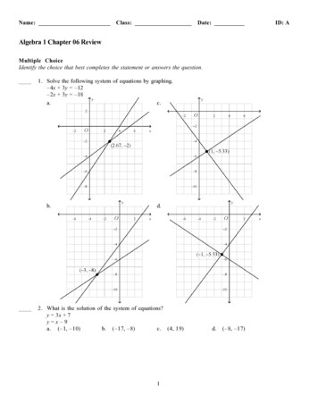
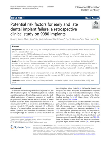
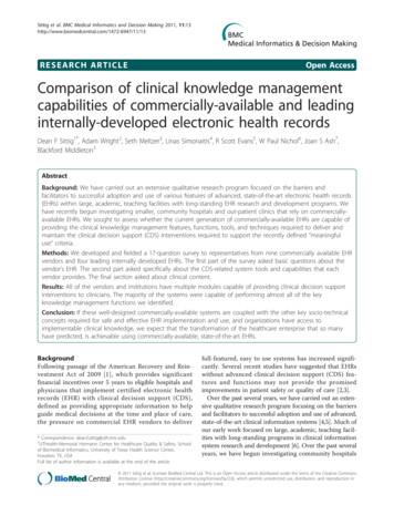
\B E D I E N E L E M E N T E CONTROL ELEMENTS AND TERMINALSMC-4 Front Panel123567841 POWERThis red LED lights up when the unit is switched on with the rear panelPOWER switch.Refer to the chapter »OPERATIONS« formore information.2 MENUThis key selects one of the available function menus.3 SELECTUse this key to select a function within a specific function menu.4 MODEThis function menu allows to select all available conversion modes.5 AUDIO INThis function menu allows to select the digital audio formats which shouldbe converted with the previously selected conversion mode.6 REFERENCEThis function menu allows to select the master clock reference for synchronization of the selected format conversion mode as well as the SRCs.7 STATUSThis menu indicates various signal statuses of the incoming master clockreference signal and the digital audio signal as well as the SMUX coding ofthe ADATTM output signal.8 CLOCK INThis menu indicates the clock rates of the incoming digital audio signal orof the master clock reference signal.MC-4 Rear Panel31254671 AES11 REF INThis input receives a balanced digital AES11 blank frame signal in compliance with AES11–1997/2003 as master clock reference for the SRCs.Alternatively, an AES3 digital audio signal in compliance with AES3 –1992(R1997) or a S/P-DIF digital audio signal aligned to IEC60958 can be input.The input impedance is 110 Ω (XLR connector, female).For detailed specifications on all terminals,refer to the »Pin Assignment of theConnectors« and »Technical Data« in thechapter »APPENDIX«. 889
CONTROL ELEMENTS\\\\\\\\\\\\\ 2 WCLK IN OUTThe above BNC connector (IN) receives a Word Clock or so-called »SuperClock« signal as master clock reference for the SRCs. The below BNC connector (OUT) transmits a low-jitter Word Clock signal based on the internalclock base or the selected external clock reference signal. If format conversions only are carried out, the WCLK output sends a Word Clock signalextracted from the selected digital audio reference signal.The impedances of both connectors are 75 Ω (BNC connectors, female).3 ADATTM INThese two optical inputs receive digital audio multichannel signals incompliance with the Alesis ADATTM format. Input »A« alone accepts ADATTMsignals up to 50.0kHz. For receiving ADATTM signals with higher clock ratesup to 192.0kHz, both inputs »A« and »B« are used simultaneously (ToslinkTMconnector, EIAJ standard).4 AES3 IN OUT CHAN 1– 8This interface receives and transmits 8 channels of AES3 digital audio signals each in compliance with AES3 –1992 (R1997). Alternatively, the 8 inputscan also be feeded with S/P-DIF digital audio signals aligned to IEC60958.The input and output impedances are 110 Ω. The pin assignment of the25pin D-Sub connector complies with Yamaha, AKAI, Mackie and others, too.5 ADATTM OUTThese two optical outputs transmit digital audio multichannel signals incompliance with the Alesis ADATTM format. Eight channel ADATTM with upto 50.0kHz clock rate are sent to both optical outputs, enabling a signaldoubling. For transfering ADATTM signals with higher clock rates up to192.0kHz, both outputs »A« and »B« are used to split the ADATTM signal, asdescribed on page 16, under »SMUX2 SMUX4« (ToslinkTM connector, EIAJstandard).6 S/P-DIF IN/OUTThese interfaces function as receiver and transmitter for S/P-DIF digitalaudio signals in compliance with the IEC 60958 standard. Their function depends on the selected operation mode, which is displayed on thefront panel. The impedances of all connectors are 75 Ω (Cinch connectors,female).7 MAINS IN, Power Switch Power InletThis is the main switch for switching the device on and off. Be sure tomake all connections (especially the supplied power cable) properly beforeturning on the switch. Heed the SAFETY INSTRUCTIONS at the beginning ofthis manual.Connect the supplied power cable here. Make sure that the power switchis turned off before connecting the power cable to this inlet and to thepower outlet. Line voltages within the range of 90 260V with a frequencies between 47.440Hz can be applied. The internal power supply willautomatically make all necessary adjustments.8810
\B E D I E N E L E M E N T E INSTALLATIONContent of the BoxThe unit was packed carefully. Nevertheless we recommend to check thecontent directly after opening the package:1 x MC-41 x Power cable1 x ManualThe condition of the packaging materialand the device should be checked carefullyadditionally. If there are any damages pleaserefer to SAFETY INSTRUCTIONS, InitialOperation, and WARRANTY REGULATIONS.Placing the DeviceThe unit should be set up as closely as possible to the devices to which itwill be connected, so as to avoid excessive cable lengths. Use the 4 rubberfeets enclosed with the appliance and stick them symmetrically on thebottom side of the unit to protect the enclosure and supporting surfacefrom being damaged.The device can be mounted into a standard 19“ rack and will require 1 unit.In this case, the rubber feet cannot be attached. Install the device so thatone unit of rack space is left free both above and below the device to allowfor sufficient ventilation! The mounting depth including the terminals is160 mm/6.7“. Another 60 mm/2.4“ should be added for the required cables.Additional slide-in rails on the rack inside are recommended for safe installation. This will also avoid long-term mechanical deformation of the housing.Before installing the unit the sectionSAFETY INSTRUCTIONS locatedat the beginning of this manualshould be read carefully.!Never expose the device andaccessories to rain, moisture, directsunlight, or excessive heat producedby radiators, heaters, or spot lights!Sufficient air circulation in the environmentof the device must be ensured!!Wiring the optical ADATTM, AES/EBU and S/P-DIF interfacesADATTMConnect the optical ADAT interfaces with the help of TOSLINK -compliant optical fiber cables. Here, you can use both plastic and glass fiber-basedcables. When using plastic fiber cables, lengths of 10 meters should not beexceeded, so as to ensure the reliable transmission of signals. Glass fibercables can transfer data reliably even over greater distances.AES/EBUConnect the AES/EBU interface with the help of an electrical 25-cond. cableequipped with 25-pin D-Sub connectors. The specifications stipulate a specific cable resistance of 110 Ω. When purchasing the cable ask your retailerfor a confirmation that the cable will perform flawlessly in your specificapplication.Connect the coaxial S/P-DIF interfaces with help of unbalanced electricalcables equipped with cinch connectors on both ends. The specificationsstipulate a specific cable resistance of 75 Ω. Ask your retailer for a confirmation of this value when purchasing the cables.Wiring the Word Clock InterfacesTo allow for the synchronization of signals, the interfaces of all devicesinvolved must be properly connected to each other, so as to ensure a logicalsignal flow. Always be sure to connect the Word Clock output of the MC-4to the corresponding input of the device you wish to synchronize. Cablelengths should be kept as short as possible to minimize signal losses and/orinterferences!For the transmission of Word Clock signals electrical, unsymmetrical cableswith a resistance of 75 Ω and BNC connectors on both ends are used. Typically, such cables are marked »RG-59U, RG59B/U«.Additionally, you should make sure that the Word Clock input to be connected to the MC-4’s output have a 75 Ω terminating resistor! Most WordClock inputs allow for enabling/disabling the termination with a so-called»termination-switch«, which may be located on the outside or inside of thedevice.MUTEC offers optical cables of variouslengths that have been specifically tested forthe transmission of ADAT signals. Ask yourlocal dealer for those cables!We advise you not to buy 25pinD-Sub cables from your computerretailer! Even though such cablesmay look similar to 25pin D-Sub AES/EBUcables, they may be wired differently!!MUTEC assumes no liability for damagesresulting from the use of improperly wiredcables!Especially when working with high AES/EBUclock rates well shielded cables are imperativeto avoid increased radiation! Standard cablesare normally useable for clock rates up to50.0kHz. Special shielded cable materialshould be used for transfer of higher clockrates.Please make sure that the cableused has a resistance of 75 Ω! If acable with a different resistance isused, a dramatic deterioration of the signalquality can be the result! In this case, theperfect synchronization could be impaired.!We recommend using high-grade cables witha good shielding. A length of max. 10 meters(approx. 30 feets) should not be exceeded!For devices which have no termination of the Word Clock input, e.g. RMEHammerfall with Word Clock i/o, Alesis BRC or M-Audio ProFire Light- 8811
I N S TALLAT I O N\\\\\\\\\\\\ bridge, you can use an additional BNC-T piece to terminate the input. Plugthe T piece with its center connector into the input of the receiving device.Then, connect the cable coming from the MC-4’s Word Clock output to oneof the lateral connectors, and the other connector of the BNC-T piece to a75 Ω resistor forming the BNC termination.Basically, you should avoid »looping through« Word Clock leads by meansof passive BNC-T pieces to preserve the signal quality, as level drops will bethe result. If there is no other way to wire your set-up, please make surethat all Word Clock inputs (except for the last device in the chain) havetheir terminations disabled! In a serial Word Clock chain only the last clockinput should have a termination! Never connect more than three devices inseries to one output!8812
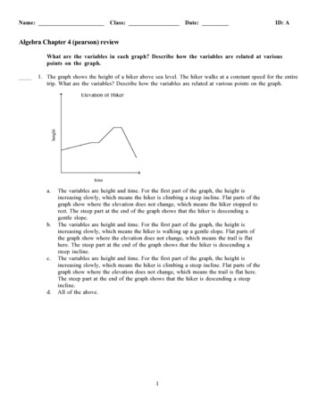
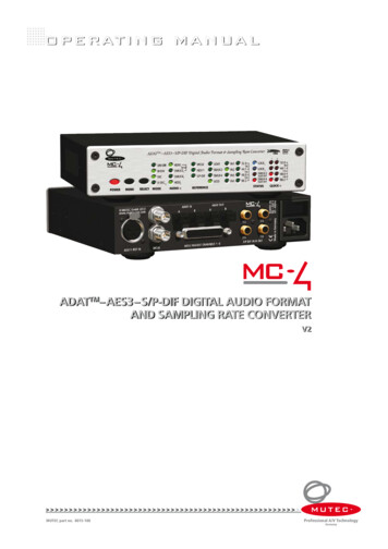
\B E D I E N E L E M E N T E GENERAL OPERATIONSelecting Function Menus and setting FunctionsThe device is fully operated using the two toggle switches at the frontpanel.1 Switching the »MENU« button toggles between different basic functionmenus.2 Switching the »SELECT« button activtes individual functions within onefunction menu.!Safety InstructionsFor safety reasons, be sure toread the SAFETY INSTRUCTIONSand INSTALLATION chapters before firstpowering-up!We also recommend reading the CONTROLELEMENTS AND TERMINALS chapter forinformation on how to connect the device!2. SELECTSelects individualfunctions withinone functionmenu.1. MENUSelects individualfunction menus.MENU SELECT operationFunctionsMenusFunction Menus FunctionsSteps of Operation1 First press on »MENU« or »SELECT« key enables the last selected functionwithin the last selected function menu. The corresponding LED isbeginning to flash.2 Every press on »SELECT« button selects a new function within a menu.The LED of the selected function flashs accordingly. After the LED stopsflashing, the function is activated.3 When the needed function is selected, do not press the switches again!After a period of approximately 4 seconds the LED of the selectedfunction stops flashing.The »STATUS« and »CLOCK IN« areas are not accessible by using the»MENU« and »SELECT« keys, because they only inform about differentconditions of incoming signals.!Shut-Down of OutputsAll digital audio outputs are shutdown during function selection!After a function is finally selected and thecorresponding LED lights constantly again,the digital audio outputs are activated forsignal transfer.!User Settings RemainAll user-specific function settingsare available furthermore whenpower is restored. 8813
\B E D I E N E L E M E N T E OPERATING THE MC-4MODE AUDIO IN REFERENCE MenusThese three function menus are offering access to the whole functionalityof your MC-4.The »MODE« menu allows to select the general conversion option as uni- orbidirectional conversion, with or without sampling rate conversion or theX-SRC mode.Within the »AUDIO IN« menu you select the digital audio formats forconversion. This menu acts in dependency of the »MODE« menu. Theoperating system makes sure that only useful combinations of conversionmodes and proper audio formats are accessable. Therefore both menus acttogether in different combinations.The »REFERENCE« menu provides all necessary synchronization options forthe corresponding conversions modes and the use of the internal samplingrate converters (SRC). This menu also acts in dependency of the »MODE«menu. It is only directly accessable when a SRC mode is selected under»MODE«.The menus »STATUS« and CLOCK IN« are for control of the MC-4‘s operationstatus only. They are not accessable for adjustments.General Operation ProcedureThe MC-4 menu is strictly organized aligned to generally usual handlingprocedures when inserting such a box into your studio‘s data stream. So,you can split up all of the necessary adjustments in three steps, which leadsto the following three questions for the basic operation of your MC-4:1) What kind of conversion should be executed MODE?UNI-DIR unidirectional conversion, from one format to all othersBI-DIR bidirectional conversion, between
Easy configurable. User's settings will be stored after switching-off. Rack space saving ½ 19" housing allowing for mounting two devices in one rack unit. Built-in international power supply. MC-4 Applications Interconnection of consumer and professional digital audio devices. ADATTM SMUX2 /4, AES3 and S/P-DIF format and sampling rate .