Transcription
GCU-10Automatic Engine Control UnitOperators ManualHeadquarters : No.3, Lane 201, Chien Fu ST., Chyan Jenn Dist., Kaohsiung, TAIWANTel : 886-7-8121771Fax : 886-7-8121775URL : http://www.kutai.com.tw
GCU-10 Automatic Engine ControlTABLE OF CONTENTSSectionPageINTRODUCTION . 31. PANEL LAYOUT. 31.1 FRONT PANEL LAYOUT. 31.2 REAR PANEL LAYOUT . 32. OPERATION . 42.1 MANUAL OPERATION . 42.2 AUTO (REMOTE START) OPERATION . 42.3 OFF OPERATION. 43. PROTECTION SETTING AND SYSTEM WARINNG FAILURE DESCRIPTION . 53.1 PROTECTION SETTING . 53.2 ICON REFERANCE TABLE . 54. SYSTEM INSTALLATION . 64.1 SPECIFICATION. 64.2 WORKING ENVIRONMENT . 64.3 PANEL CUT-OUT . 64.4 UNIT DIMENSIONS . 64.5 CONNECTION DETAILS . 74.6 STANDARD WIRING DIAGRAM ( GCU-10 WITHOUT GCU-10R). 84.7 STANDARD WIRING DIAGRAM ( GCU-10 WITH GCU-10R) . 95. TROUBLE SHOOTING . 102
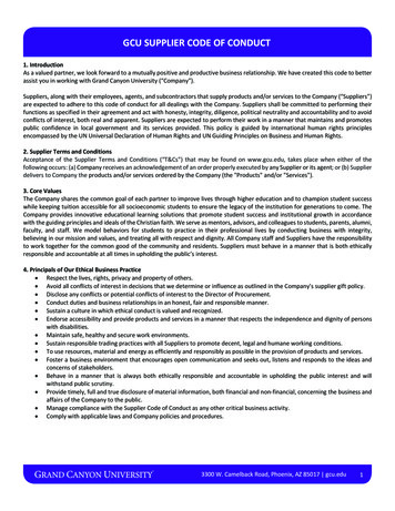
GCU-10 Automatic Engine ControlINTRODUCTION1.2 Rear Panel LayoutThe Model GCU-10 is an Automatic Engine ControlModule, designed to meet the demand of thegenerator industry. The module starts and stops thegenerator, and fault conditions, If it senses a fault itwill automatically shuts down the engine andindicates the engine failure by means of eight LED’s.The technician can program the module accordingto different generator requirements complying withdifferent conditions and protections.In the back, the GCU-10 has two terminal blocks J1& J2; five adjustment pots that change the timedelay functions and five pins dip switch that set thespecification of the genset.1. PANEL LAYOUT1.1 Front Panel LayoutOperation of the GCU-10 is by a three positionwaterproof switch, indicating AUTO, OFF, andMANUAL.Two LED's indicate POWER ON and ENGINERUNNING and the other eight LED's indicate theoperational status and fault conditions of the genset.Each LED indicates; engine start failure, high watertemperature, low oil pressure, over speed, underspeed, emergency stop, and low battery voltage. Anextra LED and corresponding input can be definedby the technician as a failure; each LED has apicture-graph that are universally recognized.A--Engine Pre-HeatAdjustable from 2 to 30secB--Engine StartAdjustable from 1 to 15secC--Engine StopAdjustable from 1 to 30secD--Engine IdleAdjustable from 0 to 300sec. Set to 0 for no Idle.E--Engine Cool downAdjustable from 0 to 300sec. Set to 0 for no Cool downSW 1 - Generator FrequencyON - 50HzOFF - 60HzSW 2 - Battery VoltageON - 12 Volt operationOFF - 24 Volt operationSW 3 - Stop SolenoidON - Energize to StartOFF - Energize to StopSW 4 - Oil Pressure SwitchON - Normal Open NOOFF - Normal Close NCSW 5 - Oil Pressure Switch (Crank Disconnect)ON - Not used for crank disconnectOFF - Used for crank disconnectGCU-10KUTAI3
GCU-10 Automatic Engine Control2. OPERATION2.1 Manual OperationTo initiate a start sequence moves the front controlto MANUAL.TheLEDabovetheknobilluminates indicating the generatoris in MANUAL.First the pre-heat timer begins by energizingterminal 4. Don’t care the terminal 4 output if thepre-heat function is no used.After pre-heat ends, the module de-energizesterminal 4 and begin engine starting.The module Fuel Solenoid energizes terminal 10,together with Engine Idle terminals 14 & 15.After a 1 sec. delay, the starter motor engages, andthe engine cranks for the duration of the crank timer.When the engine fires, the starter motor isdisengaged and locked out with an 18-Hertz signalfrom the generator output. Alternatively, the oilpressure switch can serve as an additional back upcrank release.When the engine fires and the Engine Idle option isused, the ENGINE RUNNING LED will continuousflashing in Idle period indicating the status is IDLE.Should the engine not fire on the first attempt andthe crank timer expires the module will once againattempt to start the engine until the engine fires orafter the third attempt is completed.Should the generator fail to start,place the front knob in the OFF(Reset) mode. Establish why theengine failed to fire before makingany more start attempts.After the generator starts, the module allows OilPressure, High Engine Temperature, Under speed,and the Auxiliary fault input to stabilize withouttriggering any faults in 20 seconds. Once the engineis running full fault protection is available.2.2 Automatic (Remote Mode) OperationBy moving the knob to the "AUTO"mode, the POWER SOURCE LEDwill start flashing indicating themodule is in AUTO and the gensetcan start at any time.In the “AUTO” position, the module monitors inputterminal 9 for a “REMOTE START” signal. Should a“REMOTE START” signal be detected a startsequence similar to previous manual start sequenceis initiated.When removes the Remote Start signal the CoolDown delay timer will count down. After the CoolDown ends, the Fuel Solenoid is ( de-energized orenergized as the case may be ) bringing thegenerator to a stop and the POWER SOURCE LEDwill start flashing, indicating the genset is on standbyand ready to start.Should the Remote start signal be re-activatedduring the cooling down period, the set willimmediately return to load.NOTEEven if the generator is executing EngineCool down Timer, The Module protectionsystem remain in operation and if any failureoccurs, the module bypasses the EngineCooling Timer shutting down the generatorimmediately.2.3 OFF OperationThe OFF position places the module into its Stop orReset mode. This will clear any alarm conditions forwhich the triggering criteria have been removed.If the engine is running and this position is selected,the module will automatically shut down thegenerator. The fuel supply will be removed andengine will be brought to a standstill. Should aremote start signal be present while operating in thismode, a remote start will not occur.By moving the knob to the OFF position, the gensetwill STOP immediately.4
GCU-10 Automatic Engine Control3. PROTECTION SETTING AND SYSTEMWARINNG FAILURE DESCRIPTION3.1 Protection FunctionsEngine fail to start reattemptEngine tries 3 times to startEngine High Water temperature ProtectionShutdown activated after 3 secondsTemperature Switch Type “Normally Open”Engine Low Oil Pressure ProtectionShutdown activated after 3 secondsOil Pressure Switch TypeNormal Open or Normal CloseEngine Over-speed ProtectionShutdown activated after 3 secondsIf set for 50Hz operation, Over-speed is activated at55 Hz3.2 Icon Reference TableICONDESCRIPTIONEXECUTIONPower SourceIndicationGeneratorstandby in AutoLED FlashingGeneratorOperatingNormallyEngine StartFailureShutdownHigh WaterTemperatureShutdownLow Engine utdownEmergencyShutdownActivatedShutdownSpare ShutdownShutdownLow BatteryVoltage WarningWarning OnlyIf set for 60Hz operation, Over-speed is activated at66 HzEngine Under Speed ProtectionShutdown activated after 5 secondsIf set for 50Hz operation, Under-speed is activatedat 45 HzIf set for 60Hz operation, Under-speed is activatedat 54 HzEmergency ShutdownShutdown activated by Normal Open ContactsSpare / User define ShutdownActivated after 5 seconds delayUsing Normal Open ContactsLow Battery Voltage WarningActivated after 5 seconds delayFor 12VDC operation set at 10 VFor 24VDC operation set at 20 VGCU-10Start-Up Grace PeriodThere is 20 seconds after engine idle ends, allalarms are ignored untile start-up grace periodexpired except the emergency stop and over speed.Once the engine is running full fault protection isavailable.KUTAI5
GCU-10 Automatic Engine Control4. SYSTEM INSTALLATIONInstall the Model GCU-10 Module on the front panelby using the two installation clips provided. Wheninstalled in a panel with too much vibration useappropriate anti-vibration isolators.4.1 SpecificationDESCRIPTION4.2 Working EnvironmentThe module works over a wide temperature range-20 to 70º C however, make allowances fortemperature rise within the control panel enclosure.Do not mount close to any heat sources withoutadequately ventilated; also, the humidity inside thecontrol panel should not exceed 90%.SPECIFICATION4.3 Panel CUT-OUT in mmDC Supply9.0 to 36 VDCAlternator Input Range5 300VACAlternator InputFrequency50/60 HzFuel Solenoid SignalOutput5 Amp @ 12/24VDCStart Signal Output5 Amp @ 12/24VDCWarm up Signal Output5 Amp @ 12/24VDCAccessory “ON” Output5 Amp @ 12/24VDCIdle Control ConductorCapacity5 Amp @ 12/24VDCOperating Temperature-20 C to 70 CRelative Humidity90% or BelowPower ConsumptionUnder 3WWeight166 g 2%:4.4 Unit Dimensions (Measurement mm)50.072.044.065.572.072.0GCU-10KUTAI6
GCU-10 Automatic Engine Control4.5 Connection DetailsSeven pins din rail terminal J1PIN No.1234567DESCRIPTIONGenerator sensing InputGenerator sensing InputOil Pressure switch InputPre-heat Signal OutputAccessory “ON” OutputDC Plant Supply Input ( V)DC Plant Supply Input (-V)NOTESConnect to Alternator OutputConnect to Alternator OutputConnect to Oil Pressure SwitchConnect to Internal heater. Supply ( V) 5 Amp ratedConnect to illuminate panel light. Supply ( V) 5 AmpSystem DC positive input (Battery Positive)System DC negative input (Battery Negative)Eight pins din rail terminal J2PIN No.89101112131415DESCRIPTIONNOTESSpare / User Define Warning Signal Signal need to be a negative switch InputInputConnect to A.T.S device. Signal needs to be aRemote Start Inputnegative switch inputConnect to Fuel Solenoid or Fuel Valve Control.Fuel Solenoid Signal OutputSupply ( V) 5 AmpStart Signal OutputConnect to Starter Motor. Supply ( V) 5 AmpConnect to External Emergency Stop Switch. SignalEmergency Stop Inputneeds to be a negative switch inputConnect to Water Temperature switch. Signal needsCoolant Temperature switch Inputto be a negative switch inputConnect to Governor (Speed Control) Idle controlIdle Signal OutputDry contacts 5 Amp ratedConnect to Governor (Speed Control) Idle controlIdle Signal OutputDry contacts 5 Amp ratedRear Panel layout7
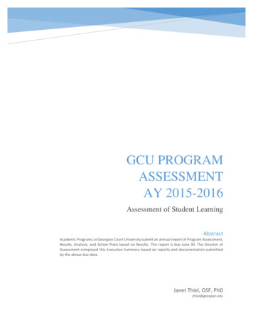
GCU-10 Automatic Engine Control4.6 Standard Wiring Diagram ( GCU-10 Without GCU-10R )LAC 5 V 300 VJ1-2NAlternatorJ1-10.5AJ1-7J1-6 Battery10A5AJ2-15Idle ControlJ2-14ElectronicGovernorIdle control5AJ1-5Accessory "ON"5AJ2-10Stop5AJ2-11Start5AJ1-4Pre-HeatGCU-10 GENERATOR CONTROL UNITJ2-9Remote StartJ2-8AUX. AlarmJ2-12Emergency StopJ2-13Temp SWJ1-3OIL SW8
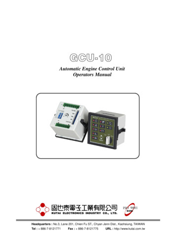
GCU-10 Automatic Engine Control4.7 Standard Wiring Diagram ( GCU-10 With GCU-10R )J1-4J2-11J2-10FromGCU5AJ2-15Idle ControlJ2-14ElectronicGovernorIdle controlJ2-9Remote StartJ2-8AUX. AlarmJ2-12Emergency StopJ2-13Temp SWJ1-3OIL SW5AJ1-5Accessory "ON"GCU-10 GENERATOR CONTROL AJ3-4Battery StopJ3-2NStartJ3-1LAlternator5 300 VACPre-Heat9
GCU-10 Automatic Engine Control5. TROUBLE SHOOTINGSYMPTOMIn “MANUAL MODE”Power Source LED doesnotilluminateandgenerator can not start.PLEASE CHECKREMEDY Check Battery Volts on cranking (Not Change Batterybelow 6V) Check DC supply Voltage Check and confirm voltage andwiring Check DC supply fuse Change fuse None of the above Change Control Unit Check Battery Volts on cranking (Not Change Batterybelow 6V)In“MANUMODE”Power Source Indicationilluminates and StarterMotor fails to operate. Check oil pressure switch type Correct Oil pressure Switch typeto correct setting Check GCU-10 Start signal output Change Control Unit Check Starting motor Change Starting motor Check wiring to see if it is open circuit Correct the fault pointIn “MANUAL MODE”Power Source LEDilluminates and StarterMotor ails to crank. Check fuel Add fuel Check wiring of fuel solenoid Correct Engine Stop Mode setting Check Governor and wiring Change Governor Check Battery Volts on cranking (Not Change Batterybelow 6V)In “MANUAL MODE”Starter Motor cranks butengine fails to firedStarting motor does notdisengageaftergenerator startsEmergency stop always.Engine not operatingAnd does not startLow oil pressure alwayswhile engine is running Check Starting circuit and wiring Change Wiring Check oil pressure Switch Change appropriate oil pressureswitch or cancel the Oil PressureDetection Engine Start option Check AC Input Voltage (5 300VAC) ChangeAutomaticRegulator (AVR)Voltage Check wiring to see if it is open circuit Correct the fault point Check oil pressure switch Change appropriate oil pressureswitch Check Starter motor Change Starting Motor Check emergency stop terminal and Select emergency stop to normalopen inputwiring Check wiring to see if it is short circuit Correct the wiring Check engine oil pressure Add engine oil / lubricant Check oil pressure switch Change oil pressure switch Check wiring to see if it is open circuit Correct the fault pointHigh water Temp alwayswhile engine is running Check engine temperature Change water temperature switch Check water temperature switch Correct the fault point Check wiring for short circuit10
GCU-10 Automatic Engine ControlSYMPTOMIn "Auto Mode" thegenerator does not startwith a remote startsignalPLEASE CHECKREMEDY Check Engine Pre-heat countdownSetting to see if preset time (2 30sec)has been reached Check remote start signal input Correct the fault point Check GCU-10 start signal output Change Control Unit Check wiring to see if it is open circuit Correct the fault pointPre-heat does not work Check Engine Pre-heat Countdown Reset settingsSetting Check GCU-10 Pre-heat signal output Change Control Unit Check Engine Cooling Countdown ResetEnginetime setting (excessive time delayed)Countdown timeCooling Check Engine Stop Countdown timesetting (inadequate time delayed)Engine does not bestopped in off mode Check Engine Stop Mode setting Reset Engine Stop Countdowntime Check GCU-10 Engine Shutdown Reset Engine Stop Mode ChangeControl Unitoutput signal Check Fuel Solenoid Change Fuel Solenoid11
The technician can program the module according to different generator requirements complying with different conditions and protections. 1. PANEL LAYOUT . GCU-10 GENERATOR CONTROL UNIT 5A J2-14 Electronic Governor J2-15 Idle Control Pre-Heat Stop Start Battery 5A J2-10 J1-5 J2-11 Idle control 5A 5A 5A J1-7 J2-9 J1-6 J1-4 J2-8 AUX. Alarm .