Transcription
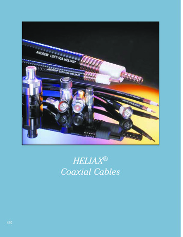
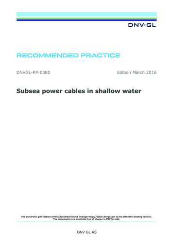
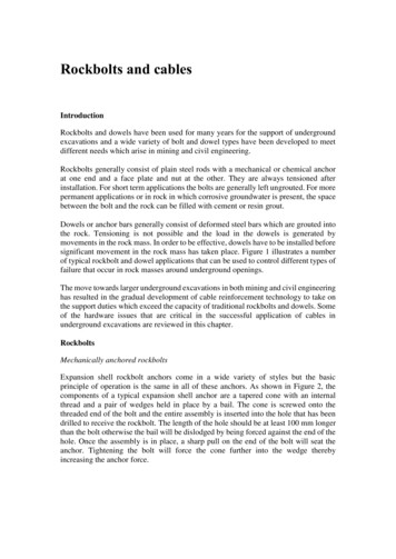
Rockbolts and cablesIntroductionRockbolts and dowels have been used for many years for the support of undergroundexcavations and a wide variety of bolt and dowel types have been developed to meetdifferent needs which arise in mining and civil engineering.Rockbolts generally consist of plain steel rods with a mechanical or chemical anchorat one end and a face plate and nut at the other. They are always tensioned afterinstallation. For short term applications the bolts are generally left ungrouted. For morepermanent applications or in rock in which corrosive groundwater is present, the spacebetween the bolt and the rock can be filled with cement or resin grout.Dowels or anchor bars generally consist of deformed steel bars which are grouted intothe rock. Tensioning is not possible and the load in the dowels is generated bymovements in the rock mass. In order to be effective, dowels have to be installed beforesignificant movement in the rock mass has taken place. Figure 1 illustrates a numberof typical rockbolt and dowel applications that can be used to control different types offailure that occur in rock masses around underground openings.The move towards larger underground excavations in both mining and civil engineeringhas resulted in the gradual development of cable reinforcement technology to take onthe support duties which exceed the capacity of traditional rockbolts and dowels. Someof the hardware issues that are critical in the successful application of cables inunderground excavations are reviewed in this chapter.RockboltsMechanically anchored rockboltsExpansion shell rockbolt anchors come in a wide variety of styles but the basicprinciple of operation is the same in all of these anchors. As shown in Figure 2, thecomponents of a typical expansion shell anchor are a tapered cone with an internalthread and a pair of wedges held in place by a bail. The cone is screwed onto thethreaded end of the bolt and the entire assembly is inserted into the hole that has beendrilled to receive the rockbolt. The length of the hole should be at least 100 mm longerthan the bolt otherwise the bail will be dislodged by being forced against the end of thehole. Once the assembly is in place, a sharp pull on the end of the bolt will seat theanchor. Tightening the bolt will force the cone further into the wedge therebyincreasing the anchor force.
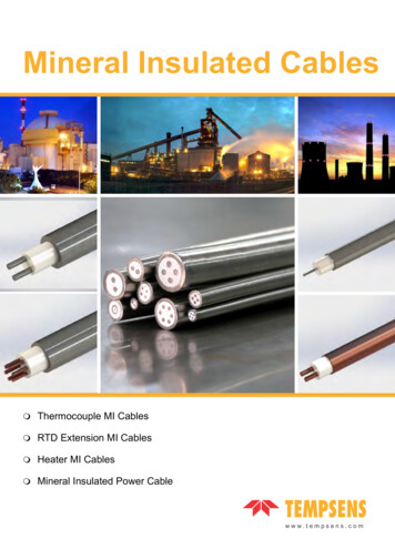
Rockbolts and cablesFigure 1: Typical rockbolt and dowel applications to control different types of rock mass failureduring tunnel driving.2
Rockbolts and cablesFigure 2: Components of a mechanically anchored rockbolt with provision for grouting.These expansion shell anchors work well in hard rock but they are not very effective inclosely jointed rocks and in soft rocks, because of deformation and failure of the rockin contact with the wedge grips. In such rocks, the use of resin cartridge anchors,described later in this chapter, is recommended.At the other end of the rockbolt from the anchor, a fixed head or threaded end and nutsystem can be used. In either case, some form of faceplate is required to distribute theload from the bolt onto the rock face. In addition, a tapered washer or conical seat isneeded to compensate for the fact that the rock face is very seldom at right angles tothe bolt. A wide variety of faceplates and tapered or domed washers are available fromrockbolt suppliers.In general, threads on rockbolts should be as coarse as possible and should be rolledrather than cut. A fine thread is easily damaged and will cause installation problems ina typical underground environment. A cut thread weakens the bolt and it is not unusualto see bolts with cut threads that have failed at the first thread at the back of the nut.Unfortunately, rolled thread bolts are more expensive to manufacture and the addedcost tends to limit their application to situations where high strength bolts are required.Tensioning of rockbolts is important to ensure that all of the components are in contactand that a positive force is applied to the rock. In the case of light 'safety' bolts, theamount of tension applied is not critical and tightening the nut with a conventionalwrench or with a pneumatic torque wrench is adequate. Where the bolts are required tocarry a significant load, it is generally recommended that a tension of approximately3
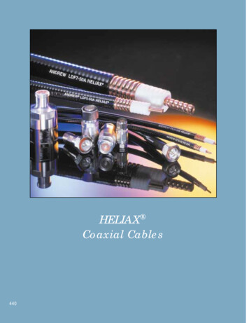
Rockbolts and cables70% of the capacity of the bolt be installed initially. This provides a known load witha reserve in case of additional load being induced by displacements in the rock mass.One of the primary causes of rockbolt failure is rusting or corrosion and this can becounteracted by filling the gap between the bolt and the drillhole wall with grout. Whilethis is not required in temporary support applications, grouting should be consideredwhere the ground-water is likely to induce corrosion or where the bolts are required toperform a 'permanent' support function.The traditional method of grouting uphole rockbolts is to use a short grout tube to feedthe grout into the hole and a smaller diameter breather tube, extending to the end of thehole, to bleed the air from the hole. The breather tube is generally taped to the boltshank and this tends to cause problems because this tube and its attachments can bedamaged during transportation or insertion into the hole. In addition, the faceplate hasto be drilled to accommodate the two tubes, as illustrated in Figure 2. Sealing thesystem for grout injection can be a problem.Many of these difficulties are overcome by using a hollow core bolt. While moreexpensive than conventional bolts, these hollow bolts make the grouting process muchmore reliable and should be considered wherever permanent rockbolt installations arerequired. The grout should be injected through a short grout tube inserted into the collarof the hole and the central hole in the bolt should be used as a breather tube. Wheninstalling these bolts in downholes, the grout should be fed through the bolt to the endof the hole and the short tube used as a breather tube.Since the primary purpose of grouting mechanically anchored bolts is to preventcorrosion and to lock the mechanical anchor in place, the strength requirement for thegrout is not as important as it is in the case of grouted dowels or cables (to be discussedlater). The grout should be readily pumpable without being too fluid and a typicalwater/cement ratio of 0.4 to 0.5 is a good starting point for a grout mix for thisapplication. It is most important to ensure that the annular space between the bolt andthe drillhole wall is completely filled with grout. Pumping should be continued untilthere is a clear indication that the air has stopped bleeding through the breather tube orthat grout is seen to return through this tube.Resin anchored rockboltsMechanically anchored rockbolts have a tendency to work loose when subjected tovibrations due to nearby blasting or when anchored in weak rock. Consequently, forapplications where it is essential that the support load be maintained, the use of resinanchors should be considered.A typical resin product is made up of two component cartridges containing a resin anda catalyst in separate compartments, as shown in Figure 3. The cartridges are pushedto the end of the drillhole ahead of the bolt rod that is then spun into the resin cartridgesby the drill. The plastic sheath of the cartridges is broken and the resin and catalyst4
Rockbolts and cablesmixed by this spinning action. Setting of the resin occurs within a few minutes(depending upon the specifications of the resin mix) and a very strong anchor is created.This type of anchor will work in most rocks, including the weak shales and mudstonesin which expansion shell anchors are not suitable. For 'permanent' applications,consideration should be given to the use of fully resin-grouted rockbolts, illustrated inFigure 4. In these applications, a number of slow-setting resin cartridges are insertedinto the drillhole behind the fast-setting anchor cartridges.Figure 3: Typical twocomponent resin cartridge usedfor anchoring and groutingrockboltsFigure 4: Typical set-up for creating a resin anchored and grouted rockbolt. Resin groutinginvolves placing slow-setting resin cartridges behind the fast-setting anchor cartridges andspinning the bolt rod through them all to mix the resin and catalyst. The bolt is tensioned afterthe fast-setting anchor resin has set and the slow-setting resin sets later to grout the rod in place.Spinning the bolt rod through all of these cartridges initiates the chemical reaction inall of the resins but, because the slow-setting 'grout' cartridges are timed to set in up to5
Rockbolts and cables30 minutes, the bolt can be tensioned within two or three minutes of installation (afterthe fast anchor resin has set). This tension is then locked in by the later-setting groutcartridges and the resulting installation is a fully tensioned, fully grouted rockbolt.The high unit cost of resin cartridges is offset by the speed of installation. The processdescribed above results in a completely tensioned and grouted rockbolt installation inone operation, something that cannot be matched by any other system currently on themarket. However, there are potential problems with resins.Most resin/catalyst systems have a limited shelf life which, depending upon storagetemperatures and conditions, may be as short as six months. Purchase of the resincartridges should be limited to the quantities to be used within the shelf life. Care shouldbe taken to store the boxes under conditions that conform to the manufacturer'srecommendations. In critical applications, it is good practice to test the activity of theresin by sacrificing one cartridge from each box, before the contents are usedunderground. This can be done by breaking the compartment separating the resin andcatalyst by hand and, after mixing the components, measuring the set time to checkwhether this is within the manufacturer's specifications.Breaking the plastic sheath of the cartridges and mixing the resins effectively can alsopresent practical problems. Cutting the end of the bolt rod at an angle to form a sharptapered point will help in this process, but the user should also be prepared to do someexperimentation to achieve the best results. Note that the length of time or the numberof rotations for spinning the resins is limited. Once the setting process has beeninitiated, the structure of the resin can be damaged and the overall installationweakened by additional spinning. Most manufacturers supply instructions on thenumber of rotations or the length of time for spinning.In some weak argillaceous rocks, the drillhole surfaces become clay-coated duringdrilling. This causes slipping of the resin cartridges during rotation, resulting inincomplete mixing and an unsatisfactory bond. In highly fractured rock masses, theresin may seep into the surrounding rock before setting, leaving voids in the resincolumn surrounding the rockbolt. In both of these cases, the use of cement groutingrather than resin grouting may provide a more effective solution.There is some uncertainty about the long-term corrosion protection offered by resingrouts and also about the reaction of some of these resins with aggressive groundwater.For temporary applications, these concerns are probably not an issue because of thelimited design life for most rockbolt installations. However, where very long servicelife is required, current wisdom suggests that cement grouted bolts may provide betterlong term protection.DowelsGrouted dowelsWhen conditions are such that installation of support can be carried out very close toan advancing face, or in anticipation of stress changes that will occur at a later6
Rockbolts and cablesexcavation stage, dowels can be used in place of rockbolts. The essential differencebetween these systems is that tensioned rockbolts apply a positive force to the rock,while dowels depend upon movement in the rock to activate the reinforcing action.Mining drawpoints, which are mined before the overlying stopes are blasted, are goodexamples of excavations where untensioned grouted dowels will work well.The simplest form of dowel in use today is the cement grouted dowel as illustrated inFigure 5. A thick grout (typically a 0.3 to 0.35 water/cement ratio grout) is pumped intothe hole by inserting the grout tube to the end of the hole and slowly withdrawing thetube as the grout is pumped in. Provided that a sufficiently viscous grout is used, it willnot run out of the hole. The dowel is pushed into the hole about half way and then givena slight bend before pushing it fully into the hole. This bend will serve to keep thedowel firmly lodged in the hole while the grout sets. Once the grout has set, a face plateand nut can be fitted onto the end of the dowel and pulled up tight. Placing this faceplace is important since, if the dowel is called on to react to displacements in the rockmass, the rock close to the borehole collar will tend to pull away from the dowel unlessrestrained by a faceplate.Figure 5: Grouted dowel using a deformed bar inserted into a grout-filled holeIn mining drawpoints and ore-passes, the flow of broken rock can cause seriousabrasion and impact problems. The projecting ends of grouted rebars can obstruct theflow of the rock. Alternatively, the rebar can be bent, broken or ripped out of the rockmass. In such cases, grouted flexible cable, illustrated in Figure 6, can be used in placeof the more rigid rebar. This will allow great flexibility with impact and abrasionresistance.7
Rockbolts and cablesFigure 6: Grouted cables can be used in place of rebar when more flexiblesupport is required or where impact and abrasion can cause problems with rigidsupport.Older type grouted dowels such as the Scandinavian 'perfobolt' or dowels, where thegrout is injected after the rod has been inserted, tend not to be used any more. Theinstallation is more complex and time co
between the bolt and the rock can be filled with cement or resin grout. Dowels or anchor bars generally consist of deformed steel bars which are grouted into the rock. Tensioning is not possible and the load in the dowels is generated by movements in the rock mass. In order to