Transcription
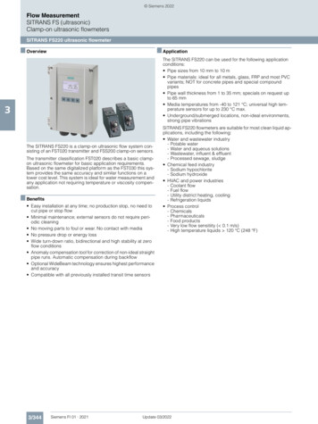
RApplication NoteGE PanametricsUltrasonic Flow MeterPart IITransducer InstallationPhysical Installation Requirements and Pipe Preparation1. Install the transducers on a straight run of pipe free of valves, flanges orelbows. For best accuracy, this run of pipe should be 15 pipe diametersin length.2. Locate the transducers so that there is a length of at least 10 pipediameters of straight, undisturbed pipe upstream from the pointof measurement and 5 pipe diameters of straight, undisturbedpipe downstream from the point of measurement. If less straight,undisturbed pipe is available use the 2/3 up and 1/3 down rule, thatis, locate the transducers such that 2/3 of the available straight,undisturbed pipe is upstream and 1/3 of the available straight,undisturbed pipe run is downstream. See Figure1.2/31/3Directionof FlowApproximateLocation of FlowTransducersFigure 1: Location of transducers on straight run of pipe.3. The transducers can be installed on a horizontal run of pipe or a verticalrun of pipe with flow going up. NEVER install on a vertical run of pipewith flow going down; the excessive turbulence will interfere with theultrasonic signal.4. Prepare the pipe. On the section of pipe where the clamping fixture,rails and transducers will be installed cut back the insulation, removeany paint, clean the pipe and sand off any corrosion or rough spots. Ifthe pipe is extremely rough the ultrasonic signal will be scattered by therough surface and will not be received by the flow meter, preventing flowmeasurement.Page 1 of 9
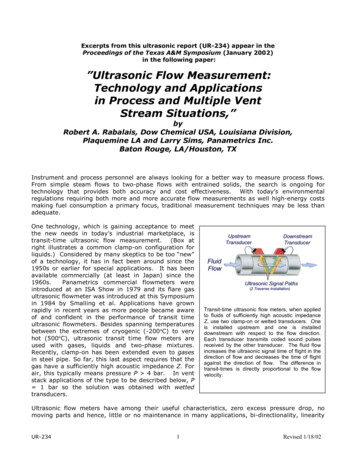
Installing #402 Transducers on Pipes Greater than 2” in DiameterFor pipes larger than 2” in diameter, #402 transducers are usually used. Inthis case, the two transducers are clamped to the pipe using a clampingmechanism as shown in Figure 2. The mechanism consists of two clampsconnected by a pair of rails and secured to the pipe using chains andthreaded hooks.Figure 2: Transducers installed onpipe.1. Before installation, make note of the Transducer Spacing valuecalculated by the PT878 on the Path tab, as described in Part I of thisApplication Note.2. Slide the un-indexed rail into the slots on the two clamping fixtureslocated opposite the chain hooks, as shown in Figure 3A.3. Slide the indexed rail into the slots on the two clamping fixtures locatedclose to the chain hooks. Line the zero end of the indexed rail up exactlywith the outside edge of one of the clamping fixtures, as shown in Figure3B. Tighten the red screws on the marked and unmarked rails on thisclamping fixture.4. Slide the other clamping fixture along the indexed rail so that the insideedge of the fixture is lined up with the value on the rail that matches theTransducer Spacing value. See Figure 3C.5. Tighten the remaining red screws on the clamping fixtures to secure it tothe rails.ABCFigure 3: Transducer clamp setup.A) Insert the un-indexed rail into the slots on the clamping fixtures located opposite thechain hooks. Then insert the indexed rail into the slots on the opposite side of the clamps.B) Line up the zero end of the indexed rail exactly with the outside edge of one of theclamping fixtures.C) Move the other clamping fixture along the indexed rail so that the inside edge of thefixture lines up with the value on the rail that matches the transducer spacing value. InPage 2 of 9this image the transducer spacing value is 3.55 inches.
6. See Figure 4. For horizontal pipe runs, transducers should be placedwithin a cone 30 above and 30 below the horizontal axis of pipe to avoidsignal interference from air and sediment.7. Prepare the pipe in the areas that the transducers are to be installedas described in the Physical Installation Requirements and PipePreparation section above.8. Install the clamping fixtures by wrapping each chain around the pipe andattaching it to the threaded hook. Tighten wing nuts to hold fixtures inplace. Hand tighten only! See Figure 5A, 5B, and 5C.9. Note that the transducers must be placed so that their co-axial cableconnectors point away from each other, as shown in Figure 2 and Figure5E.10. Insert the transducers into the clamping fixtures to make sure they willfit between the set screws and the pipe. Adjust the set screws soFigure 4: Transducer placement onhorizontal pipe run.that couplant will not be scraped off the transducers when they areinserted. Remove the transducers.11. Spread a thick ridge of silicon grease across the center of the transduceralong the line where it will contact the pipe. Reinsert the transducerinto the appropriate clamping fixture. Use CPL-1 silicon grease forgeneral applications below 150F and G-9030 silicon grease for highertemperature applications.12. Replace transducer under set screw and tighten firmly with the largebolts located in the center of the clamping fixture. Hand tighten only!See Figure 5E.CouplantCPL-1G-9030Temp Range-40 - 150 F(-40 - 66 C)-40 - 445 F(-40 - 230 C)ABCTable 1: Ultrasonic CouplantsDEFigure 5: Installing transducer clamps and transducers.A) Wrap each chain around the pipe.B) Attach chain to threaded hook.C) Tighten wing nut to hold clamping fixture in place. Hand tighten only!D) Insert transducers into clamping fixtures to make sure they will fit. Make adjustmentsas needed and remove transducers.E) Add a thick ridge of couplant to transducers. Reinsert transducers into the appropriateclamping fixture. Tighten set screws firmly with the set screws located in the center ofeach clamping fixture. Hand tighten only!Page 3 of 9
13. Repeat steps 11 and 12 for the second transducer.14. Attach the cables to the transducers. Make note of the color of the cablesleeve that is attached to the upstream transducer and the downstreamtransducer. See Figure 6.Downstream Transducerwith BLUE Cable Sleeve.Direction of FlowUpstream Transducerwith RED Cable Sleeve.Figure 6: Identifying upstream and downstream cables. Note that the upstreamtransducer cable connector has a RED cable sleeve and the downstream transducercable connector has a BLUE cable sleeve. On the meter-end of the cables, the connectorswith the same color cable sleeves must be attached to corresponding upstream anddownstream jacks on the TP878 meter.15. Proceed to Attaching Cables to Meter Section of this Application NotePage 4 of 9
Installing #24 Transducers on Pipes 2” in Diameter or LessSee Figure 8. To measure flow in small pipes, #24 transducer setsare usually used. In these sets, the transducers are part of a unit thatincludes the transducers, a black metal bracket and mounting straps. Thetransducers are attached to a pipe with hook-and-loop straps.1. Before installation, make note of the Transducer Spacing valuecalculated by the PT878 on the Path tab, as described in Part I of thisApplication Note.2. Loosen the set-screw of the movable transducer and slide it until the leftedge of the position indicator is lined up with the value on the indexedbracket that matches the Transducer Spacing value, as shown inFigure9.Figure 8: Small-pipe Transducersinstalled on pipe.Figure 9: A set-screw is attached to one of the small transducers and to the transducerspacing indicator.3. Spread a thick ridge of silicon grease across the center of eachtransducer Use CPL-1 silicon grease for general applications below150F and G-9030 silicon grease for higher temperature applications. SeeTable 1 for specific temperature ranges.4. See Figure4. For horizontal pipe runs, transducers should be placedwithin a cone 30 above and 30 below the horizontal axis of pipe to avoidsignal interference from air and sediment.5. Hold the transducer bracket close to the pipe in an appropriate location.Bring the hook-and-loop straps around the pipe a thread each onethrough its corresponding slot, as shown in Figure 10.Figure 10: Securing one end of the small-pipe ultrasonic flow transducers using thehook-and-loop connector strap.6. Push the transducers and bracket against the pipe, tighten the strapsand lock the transducer unit in place by adhering the hook and loopsurfaces of the straps.Page 5 of 9
Installing #407 Transducers#407 transducers can be used with pipes from 1/2” to 6” in diameter. Theirconfiguration is similar to that of #24 transducers, such that the instructionsfor installing #24 transducers can be used as a guide for the #407s.Attaching Cables to Meter1. Attach the other ends of the transducer cables to the PT878 meter.Make sure that the cable connected to the upstream transducer isinserted into the transducer cable port closer to the outside edge of themeter. Make sure the cable connected to the downstream transducer isinserted into the adjacent port. See Figure 7.IR PortPower PortInput/OutputPortDownstreamTransducer PortUpstreamTransducer PortFigure 7: PT878 ports. The upstream transducer port is closer to the outside edge ofthe meter. The downstream transducer port is adjacent to the upstream port. Use thecable sleeve colors to assure that the transducer cables connect the downstream anddownstream ports to the corresponding transducers.2. After the meter settles, a reasonable flow reading should be displayedon the meter. If there is a flashing Error Code Message (the letter Efollowed by a number flashing in the main screen’s System Tray) refer tothe diagnostics section of this Application Note.Page 6 of 9
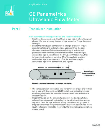
Removing Transducers1. Remove the ultrasonic transducers before removing the clamps andrails to reduce the risk of dropping and damaging the transducerconnectors.2. Clean all couplant from transducers and other equipment beforereturning them to the case.DiagnosticsPT878 provides error messages and diagnostics to alert the user toproblems with meter configuration or transducer installation and to assistin trouble-shooting these problems. A set of key diagnostic parameterscan be viewed on the PT878’s diagnostic test screen, or the meter canbe configured to display selected diagnostic parameters on the mainmeter screen. In addition to this Application Note, Chapter 9 in the PT878Operation & Installation Guide also provides information on interpretingdiagnostics and trouble shooting.1. To view the Diagnostic Tests screen (Figure 11), press F2 (Diagnostics),or press the Menu button and select Services and then Diagnostics.Figure 11: Diagnostics Tests screen.Error Codes2. If an error code other than 0x0000 appears (top left-hand corner ofDiagnostic Test screen), refer to Table 9-1 in Chapter 9 of the PT878Operation & Installation Guide. For each error code, the table describesthe problem indicated, the possible cause, and actions that may remedythe problem. Note that error codes will also appear in a box in theSystem Tray, located in the lower left-hand corner of the main meterscreen.Page 7 of 9
Sound Speed3. If the sound speed measured by the PT878 differs significantly from theexpected sound speed for the fluid in question, it indicates a problemwith meter configuration or transducer installation. For any fluid fromthe PT878 predefined fluid list, the PT878 displays an expected soundspeed in Sound Speed field on the Fluid tab. If the measured soundspeed is outside of the sound speed range indicated on the Fluid tab,and a Sound Speed (E2) Error will be displayed. For water, the PT878 will look up the expected sound speed based onthe fluid temperature input by the user in the Temp field on the Fluidtab. For water-glycol mixtures, the unit defaults to 4915 f/s. If an E2 errorresults, try changing the fluid to Other and setting the sound speed to5150 f/s.4. If the user is unsure of the fluid sound speed, the PT878 can attempt tofind the correct value by activating the Tracking Windows option of theFluid tab.5. If the measured sound speed is stable, but still results in an E2 error,on the Fluid tab, the fluid can be changed to Other and the measuredsound speed entered as the expected sound speed. If the sound speedremains stable after this change, then this is the correct sound speed.6. For sound speed data for a variety of fluids, see the Sound Speeds andPipe Size Data Installation Reference provided with the PT878.Signal Peak location (P#)7. Signal Peak (P#). The transducer signal peaks in a signal window thatis represented by arbitrary time units from 0 to 1000. The value of P#indicates where the peak occurs on this scale. For the most reliablesignal, the peak should occur near the middle of this window or at aP# value of about 500. If the P# value is below 100 or above 900, nosignal is recognized and indicates a problem with meter configuration ortransducer installation.Signal Strength (SS, or Signal)8. The table below indicates the quality of the ultrasonic signal based on itssignal strength value. The value of the upstream signal strength (SS up)should equal downstream value (SS do).SS40s50s60-6870sSignal QualityPoor to MarginalOkay to GoodVery Good to ExcellentPotential Signal VariationOther Parameters9. For a complete list of diagnostic parameters, including descriptions andguidance for interpreting their values, see Chapter 9, Table 9-2 in theOperation & Installation Guide.Page 8 of 9
Trouble ShootingIf any of the diagnostic parameters indicate a problem, the user shouldcomplete as many of the following steps are necessary to solve the problem.1. Review all meter configuration settings and make any necessarycorrections. Be sure number of traverses is set correctly.2. Consult with the facilities manager for the project site to make sure thepipe is and will be full of fluid.3. Inspect the piping where the transducers are installed to make surethe transducers are located 10 pipe diameter downstream and 5 pipediameters upstream from any valves, pipe fittings, pumps or otherintrusion into the pipe. If 15 pipe diameters of straight pipe are notavailable, check to see that the “2/3 up and 1/3 down rule” has beenapplied, keeping in mind that there may not be enough clear, straightpipe to get a valid signal.4. Remove the transducers and make sure the pipe is clear of paint andcorrosion.5. Reinstall the transducers, making sure that plenty of couplant is applied,that the transducer spacing is correct, and that the rails are parallel tothe pipe.6. Make small adjustments to the transducer spacing and see if resultsimprove.7. Once all other steps have been tried, call the Tool Lending Library at(415) 973-9945 to request assistance.Page 9 of 9“PG&E” refers to Pacific Gas and Electric Company, a subsidiary of PG&E Corporation. 2010 Pacific Gas and Electric Company. All rights reserved.These offerings are funded by California utility customers and administered by PG&E under the auspices of the California Public Utilities Commission.
3. If the sound speed measured by the PT878 differs significantly from the expected sound speed for the fluid in question, it indicates a problem with meter configuration or transducer installation. For any fluid from the PT878 predefined fluid list, the PT878 displays an expected sound speed in Sound Speed field on the Fluid tab. If the .