Transcription
STCC5011, STCC5021USB charging controller with integrated power switch and attachdetectorDatasheet - production dataApplications USB ports/hubs Personal computers, all-in-one PCs Monitors Notebooks, ultrabooksVFQFPN 16L - 3 x 3 x 0.8 mm Tablet PCs Universal wall charging adaptersFeaturesDescription Compliant with USB charging specificationsBC1.2, USB 2.0 and USB 3.0 standardsThe STCC5011/STCC5021 device integrates, inone package, a USB charger controller, a widebandwidth data switch and a high current powerswitch. The device emulates several profilescompatible with the USB battery chargingstandard BC1.2, Chinese telecommunicationsstandard YD/T 1591-2009 and proprietarycharger modes. Compliant with Chinese telecommunicationsindustry standard YD/T 1591-2009 Compatible with proprietary charging mode(Apple 1 A / 2 A, BlackBerry , Korean tablets) Wide bandwidth, low-loss USB 2.0 data switch Integrated VBUS power switch with low RON of65 mΩ Constant current mode overcurrent protection Soft-start to limit inrush current Adjustable current limit up to 2.8 A Short-circuit, thermal and undervoltageprotection Reverse voltage and reverse current protection Deglitched fault reporting output Supports remote wakeup in S3 Charging indication output in DCP and CDPmodes 3-hour safety counter for charging in S5 Device attachment detection in G3 state Available in VFQFPN 16L3 x 3 x 0.8 mm package with exposed pad Temperature range: -40 up to 85 CThe device can detect peripheral deviceattachment when the host is in a G3 state. Itasserts the CHARGING/ATTACH output after theattach event, allowing the host to turn on the highpower DC-DC converter and start charging.This device also asserts the CHARGING/ATTACHoutput in DCP modes if the charging current isabove the threshold. In CDP mode, it asserts theCHARGING/ATTACH output after the CDPnegotiation if the charging current is above thethreshold.After the current drops below the threshold, theoutput is deasserted. This allows the host to turnoff the high power DC-DC converter and reduceoverall consumption in S4/S5 states which iscritical when the host is battery-supplied.These two features permit the host system toreduce consumption while no device is attachedor when there is no charging. UL and CB recognized components(UL file number: E354278)February 2014This is information on a product in full production.DocID024660 Rev 51/36www.st.com
ContentsSTCC5011, STCC5021Contents1Functional description . . . . . . . . . . . . . . . . . . . . . . . . . . . . . . . . . . . . . . . 32Pin description . . . . . . . . . . . . . . . . . . . . . . . . . . . . . . . . . . . . . . . . . . . . . 53Absolute maximum ratings and operating conditions . . . . . . . . . . . . . 64Electrical characteristics . . . . . . . . . . . . . . . . . . . . . . . . . . . . . . . . . . . . . 75Application information . . . . . . . . . . . . . . . . . . . . . . . . . . . . . . . . . . . . . 125.1Supported modes . . . . . . . . . . . . . . . . . . . . . . . . . . . . . . . . . . . . . . . . . . . 135.2Remote wakeup in S3 . . . . . . . . . . . . . . . . . . . . . . . . . . . . . . . . . . . . . . . 145.3VBUS discharge . . . . . . . . . . . . . . . . . . . . . . . . . . . . . . . . . . . . . . . . . . . . 145.4State machine . . . . . . . . . . . . . . . . . . . . . . . . . . . . . . . . . . . . . . . . . . . . . . 155.5Attach detection . . . . . . . . . . . . . . . . . . . . . . . . . . . . . . . . . . . . . . . . . . . . 165.6Charging detection and safety timer . . . . . . . . . . . . . . . . . . . . . . . . . . . . . 175.7Power switch . . . . . . . . . . . . . . . . . . . . . . . . . . . . . . . . . . . . . . . . . . . . . . 205.8EN functionality . . . . . . . . . . . . . . . . . . . . . . . . . . . . . . . . . . . . . . . . . . . . 215.9Input and output capacitors . . . . . . . . . . . . . . . . . . . . . . . . . . . . . . . . . . . 226Typical operating characteristics . . . . . . . . . . . . . . . . . . . . . . . . . . . . . 237Package information . . . . . . . . . . . . . . . . . . . . . . . . . . . . . . . . . . . . . . . . 338Ordering information . . . . . . . . . . . . . . . . . . . . . . . . . . . . . . . . . . . . . . . 359Revision history . . . . . . . . . . . . . . . . . . . . . . . . . . . . . . . . . . . . . . . . . . . 352/36DocID024660 Rev 5
STCC5011, STCC50211Functional descriptionFunctional descriptionThe STCC5011 and STCC5021 devices integrate, in one package, a complete solution tocharge portable devices through USB ports. Functions include: Charger emulator compatible with USB battery charging BC1.2 standard, Chinesetelecommunications standard YD/T 1591-2009 and proprietary chargers such asApple divider mode, BlackBerry and Korean tablet charging mode. The Apple divider mode comes in 2 profiles:–1 A max. current drawn: for Apple iPod , iPhone (STCC5011)–2 A max. current drawn: for Apple iPad , supporting also Apple iPod and iPhone(STCC5021) 3 control pins, CTL1, CTL2, CTL3 allowing the host to select the emulation profile.These pins may be controlled directly from the host USB controller or from theembedded controller. USB data switch with wide bandwidth up to 1100 MHz compliant with USB 2.0standard. This wide bandwidth switch features low capacitance and low RONresistance, allowing signals to pass with minimum edge and phase distortion. N-channel power switch with low RON resistance of 65 mΩ typ., high current limiteraccuracy and high current output capability, 2.5 A typ. The current limit threshold canbe adjusted with a good accuracy by an external resistor in the range 500 mA to 2.8 A.Constant current mode protection is used to protect the device and the host systemagainst overcurrent or short-circuit. Other protection includes reverse current andreverse voltage protection, undervoltage lockout and thermal shutdown. A deglitched output (FAULT) reporting the failure events of overcurrent, thermalshutdown and reverse current (backdrive) to VIN. Charging current sensing circuit. The output CHARGING/ATTACH is asserted ifcharging current is above 20 mA in CDP and DCP modes.In CDP mode the charging flag is asserted only if the CDP handshaking between theportable device and the host is performed before the current is above the threshold.Moreover, in S4/S5 power states and battery supplied, there is an additional safetytimer to stop the charging process when the “end of charge” timeout is reached. Thistimer is started only after a device attachment event and can be disabled by togglingthe pin ATTACH EN to low if the timer is not wanted.If the timeout or current is below the threshold, the signal CHARGING/ATTACH isdeasserted: in both cases, the host system can disable the high power DC-DCconverter and therefore reduce power consumption. This is crucial when the host isbattery supplied. Attach detector circuit to monitor device attachment.This circuit is enabled by driving the ATTACH EN pin high and EN low. When a deviceattachment is detected, the output CHARGING/ATTACH is asserted for a tATTACHperiod (25 s typ.). The attach detection block is supplied by the VDD power supply pin. An enable input (EN) to enable/disable the device, except the attach detection switchwhich is also managed by the ATTACH EN input.The device is offered in a small, RoHS-compliant VFQFPN 16L (3 x 3 x 0.8 mm) packagewith an exposed pad for effective cooling.DocID024660 Rev 53/3636
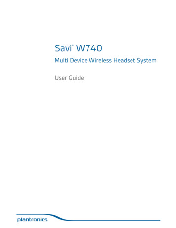
Functional descriptionSTCC5011, STCC5021Figure 1. Block diagramFigure 2. Pinout4/36DocID024660 Rev 5
STCC5011, STCC50212Pin descriptionPin descriptionTable 1. Pin descriptionPinno.NameType1INPWR2, 3DM OUT, DP OUTI/OUSB 2.0 data connection to system USB transmitter (DM D-, DP D )4ATTACH ENILogic level control input to turn on/off the attach detector (see Table 6). Itcan also disable (logic low) the 3-hour timer if started.5ENILogic level control input. When EN is low, power switch, data switch andemulator are OFF.6, 7, 8CTL1, CTL2, CTL3ILogic level control inputs to select charger mode (see Table 5).9CHARGING/ATTACHOActive low open drain output, asserted when device attachment orcharging current is detected.10, 11DP IN, DM INI/OUSB 2.0 data connection to system USB connector (DM D-, DP D )12OUTPWR13FAULTOActive low open drain output, asserted when overcurrent,overtemperature or reverse voltage are ice and USB port power supply inputUSB port power supply output (VBUS)Attach detector power supply.VDD must always be supplied before VIN.Current limit threshold programming resistor terminalDocID024660 Rev 55/3636
Absolute maximum ratings and operating conditions3STCC5011, STCC5021Absolute maximum ratings and operating conditionsStressing the device beyond the rating listed in Table 2: Absolute maximum ratings (AMR)may cause permanent damage to the device. These are stress ratings only and functionaloperation of the device at these or any other conditions beyond those indicated in Table 3:Operating conditions is not implied. Exposure to absolute maximum rating conditions forextended periods may affect device reliability.Table 2. Absolute maximum ratings (AMR)SymbolVIN, VDD, VOUTParameterVCHARGING/ATTACHVDP OUT, VDM OUT,VDP IN, VDM INIDP OUT, IDM OUT,IDP IN, IDM INIO(OUT)IO(FAULT),IO(CHARGING/ATTACH)Unit-0.3 to 6.5V-0.3 to VIN 0.3V 50mAInternally limitedA25mASupply voltageVEN, VATTACH EN, VCTLx Logical input voltageVFAULT,ValuePull-up resistor voltage (FAULT, CHARGING/ATTACH)Data switch pin voltage to groundData switch current, switch ONMaximum power switch output current, power switch ONLogical output sink currentTSTGStorage temperature (VIN OFF, VDD OFF)TSLDLead solder temperature for 10 second temperature(VIN OFF, VDD OFF)(1)260RthjaThermal resistance junction-to-ambient VFQFPN 16L(2)60 C/WTjMaximum junction temperature range (internally limited)-40 to TSTOP CVESD(OUT, DP IN, DM IN) IEC61000-4-2 contact discharge (OUT, DP IN, DM INVESD-55 to 150pins)(3)JEDEC human body model (all pins)JEDEC machine model (all pins)82200 CkVV1. Reflow at temperatures of 255 C to 260 C for time 30 seconds (total thermal budget not to exceed180 C for a period from 90 to 150 seconds).2. Rth are typical values, given when mounted on a 4-layer PCB with vias.3. Measured in a recommended application circuit with a 1 μF ceramic capacitor 150 μF low ESR electrolytic capacitorconnected between OUT and GND pins (see Figure 4).Table 3. Operating conditionsSymbol6/36ParameterValueVINSupply voltage4.5 to 5.5VDDSupply voltage1.7 to 5.5TAAmbient operating temperature-40 to 85TJJunction operating temperature-40 to 125DocID024660 Rev 5UnitV C
STCC5011, STCC50214Electrical characteristicsElectrical characteristicsTable 4. Electrical characteristics VIN 4.5 V to 5.5 V, VDD 1.7 V to 5.5 V, -40 C TJ 125 C(unless otherwise specified)SymbolParameterConditionsMin. Typ. Max.UnitCurrent consumption (VIN domain)IIN(ACTIVE)IIN(DISABLED)Mode CDP (111)110160Mode SDP (110 - 010)100150260110290180Mode DCP BC1.2 (100)110180Mode DCP divider (101)210290CTLx 000, OUT floating0.15CTLx 000 or OUT grounded,TJ 25 C0.25Mode DCP auto-detect (001)Supply current in active state– Divider mode(EN 1)– BC1.2Supply current in disablestate (EN 0)TJ 125 CµAµA60Power switch - DC parametersRON IREVERSE VREVERSEIOSTJ 25 CStatic on-resistance65-40 C TJ 125 CReverse leakage current indisabled state (absolutevalue)Reverse voltage protectionthreshold (VOUT - VIN)Current limiter threshold95VOUT 5.5 V, VIN 0,TJ 25 C, VEN 0,measured at IN15µATJ 125 C, other conditions thesame as above70VUVLO VIN VOUT, EN 1,power switch ON - OFF60500mVRILIM 96 kΩ340RILIM 33 kΩ1290 1450 1595RILIM 19.6 kΩ2255 2450 2645RILIM 17.2 kΩ2800TSTOPEmergency OFF temperatureTHYSTThermal shutdown hysteresis20RENEN input pull-down resistor250VENEnable input turn-on, turn-offthreshold voltageVHYST(EN)Enable input turn-on, turn-offvoltage hysteresisVOL(FAULT)FAULT output low voltage1401500.4625160DocID024660 Rev 5mA CkΩ1.6500IFAULT 1 mAmΩVmV1807/3636
Electrical characteristicsSTCC5011, STCC5021Table 4. Electrical characteristics VIN 4.5 V to 5.5 V, VDD 1.7 V to 5.5 V, -40 C TJ 125 C(unless otherwise specified) (continued)SymbolParameterConditionsFAULT output leakagecurrentVIN 5.5 V, VDD 5.5 V,VFAULT 5 VtFAULTFAULT output deglitch delayFAULT assertion / deassertiondelay in overcurrent conditionVUVLOUndervoltage lockoutVIN risingVHYST(UVLO)Undervoltage lockouthysteresisTJ 25 CIOL(FAULT)Min. Typ. Max.Unit1µA7912ms3.94.14.3V100mVPower switch - AC parameters(1)tONTurn-on, EN to OUT delaytOFFTurn-off, EN to OUT delay0.8CLOAD 1 µF, RLOAD 100 Ω0.3tROUT (VBUS) rise timeCLOAD 1 µF, RLOAD 100 Ω0.4tFOUT (VBUS) fall timeCLOAD 1 µF, RLOAD 100 Ω0.2tIOSCurrent limiter response timeVIN 5.5 Vto short-circuitms3.5µsOutput dischargeRDISCHARGEDischarge resistorATTACH EN EN 0140200300Ω5.5VAttach detectorVDDIDD(ACTIVE)IDD(DISABLED) IATT REVERSE RON ATTVATTACH ENVHYST(ATTACH EN)Supply voltage1.7Supply current in active stateVDD 1.7 V to 5.5 V, VEN 0,VATTACH EN VDD, TJ 25 C1530Supply current in disabledstateVDD 1.7 to 5.5 V, VEN 0,VATTACH EN 00.13Detector switch reversecurrent (VOUT to VDD)(absolute value)VDD 0, VOUT 5.5 V,IN floating, measured at VDD0.13Static on-resistance VDD toVOUTTJ 25 C100Enable input turn-on, turn-offthreshold voltage0.4Enable input thresholdhysteresisATTACH EN input leakagecurrentVDD 5.5 V, VIN 5.5 V,VATTACH EN 0 V or 5 VVOL(CHARGING/ATTACH)CHARGING/ATTACH outputlow voltageDevice attachment detected,ICHARGING/ATTACH 1 mAIOL(CHARGING/ATTACH)CHARGING/ATTACH outputleakage currentVIN 5.5 V, VDD 5.5 V,VCHARGING/ATTACH 5 V8/36Ω1.6500IATTACH ENDocID024660 Rev 5-1µAVmV1µA180mV1µA
STCC5011, STCC5021Electrical characteristicsTable 4. Electrical characteristics VIN 4.5 V to 5.5 V, VDD 1.7 V to 5.5 V, -40 C TJ 125 C(unless otherwise specified) (continued)SymboltATTACHParameterConditionsMin. Typ. Max.Unit25sCHARGING/ATTACHassertion time after attachdetectedHigh-speed data switch - DC parametersData switch on-resistanceSwitch closed, VIN 5 V,IS 8 mA, test voltage onDP OUT, DM OUT 0.4 V2.5RONData switch on-resistanceSwitch closed, VIN 5 V,IS 8 mA, test voltage onDP OUT, DM OUT 3 V2.7IOFFOFF state leakage currentVEN 0 V, VDP/DM IN 3.6 V,VDP/DM OUT 0 V, measureIDP/DM OUTRON4Ω41.5µAHigh-speed data switch - AC parameters(1)XTALKOIRRBwDP, DM crosstalkRTERM 50 Ω, CLOAD 5 pF,VS 1 Vrms, signal 0 dBm,f 250 MHz47OFF state isolationRTERM 50 Ω, CLOAD 5 pF,VS 1 Vrms, signal 0 dBm,f 250 MHz17Bandwidth -3 dBRTERM 50 Ω, CLOAD 5 pF,signal 0 dBm1100CTLx configured for DCP BC1.21001702.652.72.751.9622.04dBMHzCharger emulator - BC1.2 DCP modeRDCP RESDP IN to DM IN shortresistanceΩCharger emulator - divider modeVDM 1ADM IN output voltageVDP 1ADP IN output voltageRDM 1ADM IN output resistanceSTCC5011, device set to DCPauto-detect mode or dividermode, VIN 5.0 VRDP 1ADP IN output resistanceVDM 2ADM IN output voltageVDP 2ADP IN output voltageV27STCC5011, device set to DCPauto-detect mode or dividermode, VIN 5.0 VSTCC5021, device set to DCPauto-detect mode or dividermode, VIN 5.0 VDocID024660 Rev 5kΩ271.9622.04V2.652.72.759/3636
Electrical characteristicsSTCC5011, STCC5021Table 4. Electrical characteristics VIN 4.5 V to 5.5 V, VDD 1.7 V to 5.5 V, -40 C TJ 125 C(unless otherwise specified) (continued)SymbolRDM 2ARDP 2AParameterConditionsDM IN output resistanceDP IN output resistanceMin. Typ. Max.Unit27STCC5021, device set to DCPauto-detect mode or dividermode, VIN 5.0 VkΩ27Charger emulator - BC1.2 CDP modeVDM SRCVoltage source on DM IN for VDP IN 0.6 V, device in CDPCDP detectionBC1.2 mode0.5VDAT REFDP IN rising voltagethreshold to turn on VDM SRC0.25 0.32VDAT REF HYSTVLGC SRCVLGC SRC HYSTIDP SINKVDAT REF hysteresisDP IN rising voltagethreshold to turn off VDM SRCIDM IN -250 µA, device in CDPBC1.2 mode0.60.7V0.4400.8VLGC SRC hysteresismV1400.4 VDP IN 0.8 V, device inCDP BC1.2 modeDP IN sink current5075VmV150µACharger emulator - timingsFrom IOUT IOUT TH totCHG DGL ONCharging indication ONdeglitch delaytCHG DGL OFFCharging indication OFFdeglitch delayFrom IOUT IOUT TH toCHARGING deasserted5tVDM SRC ONDM IN voltage source turnon timeFrom VDP IN 0 V - 0.6 Vto VDM IN VDM SRC, CTLxconfigured for CDP BC1.28tVDM SRC OFFDM IN voltage source turnoff timeFrom VDP IN 0.6 V - 0 V toVDM IN 0 V, CTLx configuredfor CDP BC1.2tVBUS REAPPOUT discharge pulse widthFrom VOUT falling to 0.7 V duringdischarge to VOUT returning to90%.0.5CHARGING/ATTACH asserteds1.3300350ms400Charger emulator - control pins CTLxVCTLxCTLx pins threshold voltageVHYST(CTLx)Hysteresis voltage on CTLxpinsICTLx10/36Leakage current0.41.6500VDD 5.5 V, VIN 5.5 V,VCTLx 0 V or 5 VDocID024660 Rev 5-1VmV1µA
STCC5011, STCC5021Electrical characteristicsTable 4. Electrical characteristics VIN 4.5 V to 5.5 V, VDD 1.7 V to 5.5 V, -40 C TJ 125 C(unless otherwise specified) (continued)SymbolParameterConditionsMin. Typ. Max.Unit20mACharger emulator - charging indicationOutput current threshold forcharging detectionDCP mode, CDP modeVOL(CHARGING/ATTACH)CHARGING/ATTACH outputlow voltageCharging detected(IOUT IOUT TH) and chargingtime in S5 tEOCH (end ofcharge safety timer),ICHARGING/ATTACH 1 mAIOL(CHARGING/ATTACH)CHARGING/ATTACH outputleakage currentVDD 5.5 V, VIN 5.5 V,VCHARGING/ATTACH 5 VIOUT TH180mV1µACharger emulator - safety timer(1)From IOUT IOUT TH after attachCharging timeout after attach detection todetectionCHARGING/ATTACHdeassertedtEOCH3hours1. Guaranteed by design. Not tested in production.Figure 3. Timing waveforms9(1[ WRQ9287[WRII ,26,287WU9287WU W,26 0 9 DocID024660 Rev 511/3636
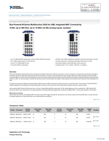
Application information5STCC5011, STCC5021Application informationThe STCC5011 and STCC5021 devices are designed to be implemented into the PC ona USB port in order to emulate the wall charger adapter when the PC is in standby mode orOFF, and to allow higher charge current when the USB interface is used for datacommunication. In order to handle these functionalities, the STCC5011/STCC5021 devicesrely on USB BC1.2 specifications, Chinese telecommunications industry standard YD/T1591-2009 and proprietary implementations BC1.2 charging profiles are:–CDP: charging downstream port providing data communication plus charging(active USB data communications with 1.5 A support)–SDP: standard downstream port providing data communication with no charging(active USB 3.0 data communications with 900 mA support or USB 2.0 datacommunications with 500 mA support)–DCP: dedicated charging port (wall charger emulation with no data communicationand 500 mA to 1.5 A support)Chinese telecommunications standard– D and D- shorted to allow chargingApple divider mode comes in 2 profiles–1 A max. current drawn by Apple iPod, iPhone (STCC5011)–2 A max. current drawn by Apple iPad, supporting also Apple iPod and iPhone(STCC5021) BlackBerry emulator mode Legacy mode (allowing 500 mA charging current) Korean tablet charging mode (D and D- shorted and pulled up to a certain voltage)Figure 4. Typical application diagram7*/ 7 GSPN IJHI QPXFS 4.14*/ */7%% 7 GSPN BMXBZT BMJWF -%0316@'"6-5316@ )( )"3(*/( "55" ) 7%%7%%06564# DPOOFDUPS45 Y )"3(*/( "55" )'"6-5 065%.@*/%1@*/'"6-5 7#64 7#64% %(/%1PXFS BOE EBUB TXJUDI FOBCMF&/"UUBDI EFUFDUPS DPOUSPM"55" )@&/ 5- .PEFTFMFDU%.@065 5- %1@065 5- *-*.(/%5P 64# IPTU DPOUSPMMFS1"%3*-*.". 1. CVBUS required by the USB specification.12/36DocID024660 Rev 5
STCC5011, STCC50215.1Application informationSupported modesFor more information refer to Section 5.4: State machine.The STCC5011/STCC5021 device supports the following modes: SDP BC1.2 CDP BC1.2 SDP with remote wakeup for all USB devices CDP with remote wakeup for low-speed USB devices with automatic transition to DCPauto-mode if a full-speed/high-speed USB device attached or after a USB devicedetached DCP auto-detect: this mode permits auto-detection of charging modes between DCPBC1.2 (shorted D , D-) and divider charging mode. It also supports BlackBerrycharging mode and can charge legacy devices and Korean tablets. Forced DCP BC1.2 mode Forced DCP divider modeThe auto-detect mode starts in divider mode. If a charging negotiation attempt is detected,there is an automatic transition to DCP BC1.2 mode. It is preceded by a VBUS dischargepulse to initialize the proper BC1.2 handshake process. If the BC1.2 device is detached, thecircuit automatically returns to divider mode after a 10 s (typ.) timeout.Note:From the application point of view it means that after removing one device the user shouldwait for approx. 15 s before attaching another device.Selection between these modes is made through the CTLx control pins. The CTLx pins maybe controlled by the host in different ways: GPIO from the embedded controller Hardware signals from the USB host controller (SLP S3#, SLP S4#) and theAC adapter signal from the embedded controller Hardware signal SUSPEND from the embedded controller and AC ADAPTER.Table 5. Truth table control pins CTLx(1)Host stateCTL1 CTL2 CTL3Mode description000Device off, output dischargeS0, S1(S3)(2)110SDPS0, S1,(S3)(2)111CDP BC1.2 with charging detection.(2)010SDP with remote wakeup for all USB devicesS3011CDP with remote wakeup for low-speed USB devices / DCP auto-modefor full-speed or high-speed USB devices or after a USB device detached.S4, S5001DCP auto-detect mode without remote wakeup, with charging detectionS4, S5101Forced DCP divider mode with charging detectionS4, S5100Forced DCP BC1.2 mode with charging detectionS3, (S0, S1)1. On the transition from the CTLx 111 to CTLx 001, a synchronous transition of the CTL1 and CTL2 must be ensured.2. See Section 5.2 for further information.DocID024660 Rev 513/3636
Application information5.2STCC5011, STCC5021Remote wakeup in S3For more information refer to Section 5.4: State machine.If the CTLx pins are controlled by hardware signals (such as SLP Sx# or SUSPEND), theCTLx combination changes when the host transitions from S0 to S3 and back. In this case,the STCC5011/STCC5021 device can support remote wakeup of portable devices for thefollowing transitions (i.e. no VBUS discharge pulse and data switch ON): SDP S0 (CTLx 110) to and from SDP S3 (CTLx 010) for all USB devices SDP (CTLx x10) and CDP S0 (CTLx 111) to and from CDP S3 (CLx 011) for lowspeed USB devices only.If the host system is in S3 mode (CTLx 011), the system automatically turns into DCPauto-mode for already attached full-speed / high-speed USB devices or after any USBdevice is detached. Thus, already attached full-speed / high-speed devices or newlyattached devices are charged without the need of CTLx transition.If the S0 to S3 transition is managed by GPIO from the embedded controller, the easiestsolution is to keep the same levels on the CTLx pins (SDP or CDP modes). Therefore,remote wakeup in S3 is supported for all USB devices but the system does notautomatically turn into DCP auto-mode.5.3VBUS dischargeThe VBUS discharge pulse lasts for 350 ms typ. (tVBUS REAPP) and is performed for anytransitions between the modes listed inTable 5, except the modes allowing remote wakeupin S3 [transitions (x10) and (111) to/from (011)].Permanent output discharge is provided in the following modes:14/36 EN 0, ATTACH EN 0, CTLx xxx (ignored) EN 1, ATTACH EN 0, CTLx 000.DocID024660 Rev 5
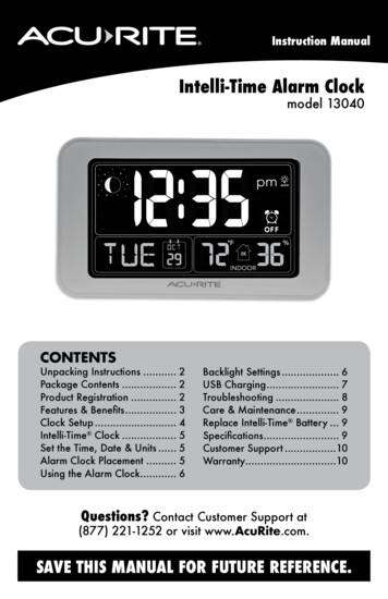
STCC5011, STCC50215.4Application informationState machineFigure 5. State machineDocID024660 Rev 515/3636
Application information5.5STCC5011, STCC5021Attach detectionThe STCC5011-STCC5021 can detect device attachment when the host system is in the G3state. The combination of logic low level on EN and logic high on ATTACH EN enables abypass switch, supplied by low power supply, VDD (see Table 6). It allows the host to keeponly low power supply LDO alive, therefore reducing its power consumption in G3 statewhile there is no device attached, but maintaining the possibility to wakeup. It also prevents“no charging” attached devices (“power thieves”) to draw current.Table 6. Attach detector truth tableATTACH ENENAttach detector0xOFF11OFF10ONThe attach detection circuit has a very low consumption (12 µA typ.) and accepts a widesupply voltage range (1.7 V up to 5.5 V).The devices already attached before entering the G3 state (EN 0, ATTACH EN 1) areignored and their current consumption is limited to 500 μA. Only devices attached afterentering the G3 state are detected.The attach detector monitors voltage drop across the bypass switch between VDD and VOUT.This voltage drop is caused either by the supply current of the attached device or by inrushcurrent for charging device internal capacitors.An open drain active low output CHARGING/ATTACH is asserted upon device detection,alerting the host system of device attachment. It stays asserted for the tATTACH delay(25 s typically). During this time the host may switch from G3 state to S5 state, start highpower 5 V supply for VIN and set proper CTLx configuration (see Figure 6).The attached device can start charging keeping CHARGING/ATTACH asserted.If charging does not occur, the flag is deasserted after the tATTACH (the attached deviceremoved or charging current drops below threshold or safety timer expires - seeSection 5.6).16/36DocID024660 Rev 5
STCC5011, STCC5021Application informationFigure 6. Attach and charging detection - timing diagram5.6Charging detection and safety timerThe STCC5011-STCC5021 devices continuously monitor current drawn by the portabledevice. While programmed in CDP or DCP mode, the STCC5011-STCC5021 devices senda charging flag to the system if the current through the USB power switch is above thecharging threshold, set at 20 mA typ.: open drain active low output CHARGING/ATTACH isasserted.Note:In CDP mode the charging flag is asserted only if the CDP handshaking between theportable device and the host is performed before the current is above threshold.If the CHARGING/ATTACH output is already asserted because of attachment detection(while the host is in G3 state), this output stays unchanged.For systems in S5 providing current charge while being battery supplied, there is a safetytimer integrated into the STCC5011-STCC5021 devices. This timer is started only after anattach event with input ATTACH EN enabled.DocID024660 Rev 517/3636
Application informationSTCC5011, STCC5021The safety timer is stopped in the following conditions: Charging current below threshold (see Figure 7). The CHARGING/ATTACH output isdeasserted. End of 3 hours (timer expires). The CHARGING/ATTACH output is deasserted. ATTACH EN transition to 0 (see Figure 8). The CHARGING/ATTACH output is intactand the charging can continue without any time limit.Figure 7. 3-hour timer - start and stopFigure 8. 3-hour timer stop (ATTACH EN low)CHARGING/ATTACH18/36DocID024660 Rev 5
STCC5011, STCC5021Application informationUse case 1: device charging in CDP, notebook is then turned offIf a device is charging while the system is turned off and the battery supplied, the risk is thatthe charging process stops before the end of charge due to the system power-off. To avoidthis, the flag CHARGING/ATTACH can be used by the host to prevent the switching-off ofthe high power DC-DC converter when the host goes to S5 state, even if battery supplied. Inthis case the 3-h timer is not started.Use case 2: charging in S5, battery suppliedOnce device attachment has been detected and the host has woken up, supplying VBUSvoltage to the portable device allows the charging process to start in DCP mode. The flagCHARGING/ATTACH stays asserted for the tATTACH period (25 s typ.) after attach. Duringthis period, the charging must be established (charging current above the IOUT THthreshold) to keep the CHARGING/ATTACH output asserted. The 3-h safety timer is startedif ATTACH EN is kept high.If, for whatever reason, there is no charging current (or if it is below 20 mA),CHARGING/ATTACH is deasserted (while ATTACH EN is still high). The host can return toits previous state by switching off the high power supply, to reduce consumption, and settingthe EN pin to 0. Therefore, the attach detector is ON. At this stage, the STCC5011STCC5021 devices can detect if the device is still attached or has been removed (seeFigure 9). If the device is still attached, the attach detector circuit waits for device removal. If the device is removed, the circuit goes back into attach detection mode till the nextattachment.Figure 9. Attach detectionDocID024660 Rev 519/3636
Application informationSTCC5011, STCC5021Figure 10. Reset of CHARGING/ATTACH and 3-hour timer after EN - 0 event5.7Power switchOvercurrent conditionsWhen an overcurrent condition is detected, the device maintains a constant output currentand reduces the voltage accordingly. There are two overload conditions: The first one occurs when a short-circuit or a partial short-circuit is already presentwhen the device is being powered up or enabled. The output voltage is held near zeropotential with respect to ground and the STCC50x1 device ramps the output current toIOS until the overload condition is removed or the device starts thermal cycle. The second condition is when a short-circuit, a partial short-circuit, or a transientoverload occurs while the device is already enabled and powered-on. The STCC50x1device responds to the overcurrent condition within time tIOS. The current senseamplifier is overdriven during this time and momentarily disables the internal currentlimit MOSFET. It then recovers and ramps the output current to IOS. Similar to theprevious condition, it limits output current to IOS until the overload condition is removedor thermal cycle starts.Thermal protectionThe STCC50x1 devices have an inter
Data switch pin voltage to ground -0.3 to VIN 0.3 V IDP_OUT, IDM_OUT, IDP_IN, IDM_IN Data switch current, switch ON 50 mA IO(OUT) Maximum power switch output current, power switch ON Internally limited A IO(FAULT), IO(CHARGING/ATTACH) Logical output sink current 25 mA TSTG Storage temperature (VIN OFF, VDD OFF) -55 to 150 C TSLD