Transcription
CM PROSTHETICSMANUAL
2
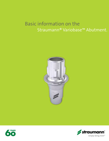
CONTENT1.0 BASIC INFORMATIONS ABOUT CONE MORSE IMPLANTS51.1 CM Implants61.2 Facility Implants81.3 WS Implants82.0 CLASSIFYING DENTAL IMPLANT PROSTHESES92.1 Level of work for dental implant prostheses: Implant or Abutment Level92.2 Type of retention: cement-retained or screw-retained prostheses112.3 Number of units: single (crown) or multiple restorations (bridge)113.0 GENERAL CARE IN THE SELECTION OF ABUTMENTS124.0 GENERAL POINTS TO BE NOTED IN THE PLACEMENT OF ABUTMENTS134.1 Overview of Cone Morse Healing Abutments4.1.1 Overview of the Cone Morse Abutments and their corresponding Healing Abutments4.2 Biological care when placing Cone Morse abutments5.0 TRANSFER OF THE IMPLANT OR ABUTMENT AND MODEL PRODUCTION131517185.1 Transfer of implants/abutments (open or closed tray impressions)185.2 Model Production196.0 SCANNING AND DIGITAL SOLUTIONS206.1. Scanbody206.2 Digital workflow for prostheses (CADCAM)216.2.1 Scanning a plaster model216.2.2 Intraoral Scanning227.0 ABUTMENT OPTIONS7.1 The implant level (screw-retained or cement-retained)2222
7.1.1 CM Pro Peek Abutment (temporary abutment)227.1.1 CM Exact Titanium Base237.2 Abutment level7.2.1 Over CM Implants7.2.1.1 CM Abutment (single-unit screw-retained)2525257.2.1.2 CM Mini Conical Abutment and CM Micro Abutment (multiple-unit screw-retained) 267.2.1.3 CM Anatomic Abutment (single-unit cement-retained)297.2.1.4 CM Universal Abutment (single-unit cement-retained)327.2.1.5 2-Piece CM Universal Abutment (single-unit cement-retained, non-indexed)347.2.1.6 CM Equator Attachment (overdenture)357.2.2 Over WS Implants377.2.2.1 WS Abutment (single-unit screw-retained)377.2.2.1 WS Mini Conical Abutment (multiple-unit screw-retained)387.2.2.3 WS Universal Abutment (single-unit cement-retained)397.2.3 Over Facility Implants407.2.3.1 Facility Micro Abutment (multiple-unit screw-retained)407.2.3.2 Facility Anatomic Abutment (single-unit cement-retained)417.2.3.3 Facility Equator Attachment (overdenture)428.0 OVERVIEW OF TORQUES AND CONNECTIONS439.0 CONVENTIONAL WORKFLOW FOR PROSTHESES (LOST-WAX TECHNIQUE, TEMPORARY CROWNS, ETC.)4410.0 CM ABUTMENT TRY IN KIT4411.0 NEODENT TECHNIQUES4511.1 One Step Hybrid4511.2 Distal Bar48BIBLIOGRAPHIC REFERENCES50
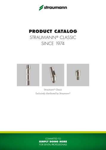
1.0 BASIC INFORMATIONS ABOUT CONE MORSE IMPLANTSThe modern implantology era, which is based on the clinical results of the concept ofosseointegration, began with the first internationally published journals in 19771. Since then, Dentistryhas had important changes and, today, a patient’s treatment plan usually offers implant retained and/or supported prosthesis as an affordable and reliable solution. The number of oral implants placed israpidly increasing2,3 and this treatment concept requires specific skills and knowledge, as the surgeon’slearning curve, that are relevant for a successful result4. Based on these facts, the present guide aimsto provide to dental practioners and specialists basic information and steps regarding the planning,surgical procedures and options of treatment. This guide does not replace the instructions for use(IFU) of each product, which can be found in our website: www.neodent.com.br. It is the surgeon’sresponsibility to analyze the patient’s general health condition, the viability of the surgical andprosthetic procedures and the most appropriate products to each clicnical situation.Implants with internal connections have begun to produce excellent clinical results and havebecome widely accepted by dental surgeons, thanks to their practicality. Internal connections rapidlybecame popular soon after their introduction. They were seen to give improved biological and mechanicalresults1. Originally described by Stephen A. Morse in 1864, the Morse taper connection is intended toprovide a more stable and reliable connection between two parts. Tapering interface adjustmentsthen began to be commonly used in engineering practices as Morse tapers, used to connect parts oflathes2. In the dental field, internal connections were adapted for use with dental implants, where thecharacteristics of this fitting, such as the forces for removal, insertion and stress distribution of theparts depend on6,7,8,9,10:1.the angle of the taper;2.the length of the contact area;3.the internal and external diameter of the parts;4.the depth of insertion;5.material properties;6.the coefficient of friction;7.the size and mass of the male connector.The Cone Morse (CM) Neodent implant system offers 6 different types of implant designs,threads, apex and two types of surface treatment. Neodent’s philosophy is to offer one implant solutionadapted to a proper indication, which is density and amount of bone available and surgical technique.(Figure 1).5
CMWSFacilityFIGURE 1. Neodent options of implants according to their indication.1.1 CM ImplantsAll Cone Morse (CM) implants present a Morse taper connection. The CM implants (Drive, Alvim,Titamax EX and Titamax) have an internal total angle of 11.5 and the same prosthetic connectiondimension, regardless of the implant diameter (figure 2).The platform switch concept7 in Neodent CM Implants has proven biological stability of the periimplant tissue, especially when the implants are placed 1-2 mm sub crestally12,13,14,15,16,17. The subcrestalpositioning of CM Implants also reduces the stress levels in the superior bone crest17. Besides that, thisconnection is designed to prevent bacterial migration to the implant core18. The main indications of theCM Implants are:-Drive CM: for bone type III and IV and postextraction insertion;-Alvim CM: for bone type III and IV, postextraction insertion and for bone type I and II withthe Alvim Bone Tap;-Titamax CM EX: for bone type III and IV and for narrow bone width;-Titamax CM: for bone type I and II and areas of block grath.FIGURE 2. Neodent CM implant connection has one width regardless of the implant diameter.6
3.8 mmFIGURE 3. Neodent CM has a deep connection inside the implant designed to enhance the contact area between theimplant and abutment.The Neodent CM conical connection features an internal hexagon index in the lower portion calledthe CM Exact. It is used to surgically position the implant and reposition prosthetic abutments whenworking at implant level.FIGURE 4. Internal hexagon index, createdto surgically guide the implant and mold theimplant during the prosthetic phase.7
1.2 Facility ImplantsFacility Implants also have a cone Morse connection, but with an internal angle of 5 . They arethe narrowest implants offered by Neodent and their abutments are placed through friction. Their use isindicated to the upper lateral incisors’ and lower incisors’ areas.FIGURE 5. Facility is the narrowest implantoffered in the system and its abutments areplaced through friction.1.3 WS ImplantsWS (short implants) is a complementary line of cone Morse implants, suitable for special areas. WSImplants also feature an internal angle of 11.5 , but different internal diameter and length. Therefore, aspecial line of abutments is required when working with these implants. They are indicated as an alternativefor posterior free ended partially edentulous ridge.3,0 mmFIGURE 6. The WS implant connection features a wider connection than the CM implant line and an exclusive line of abutments.The Neodent cone Morse system has a full portfolio, adapted to the patient’s bone density andquality.8
2.0 CLASSIFYING DENTAL IMPLANT PROSTHESESThere are several ways to rehabilitate patients using dental implants. To make this procedureeasier, a dental implant prostheses can be classified according to:-The level of the work: implant or abutment.-The retention type: cement-retained or screw-retained.-The number of elements: single (crown) or multiple.2.1 Level of work for dental implant prostheses: Implant or Abutment LevelDental implants are restored with the help of prosthetic abutments. These parts are screwedinto the implants, acting as an abutment that elevates the position of the implant (next to the bone) tothe soft tissue level, facilitating restoration. Prosthetic abutments support the soft tissue during theprocedure. Figure 7 is a schematic for restoration at the implant and abutment levels.In cases where there is little soft tissue due to anatomical limitations, poor implant positioning,or for any another reason, implants should be restored at their platform level. In such cases, abutmentsare no longer needed. Figures 8 and 9 show the clinical step of an impression at the implant level andimpressions at the abutment level (restoration at implant level/restoration at abutment level).FIGURE 7. Restorations at implant level and at abutment level.9
There are many reasons to opt for a restoration at either the implant or abutment level, especiallynow that digital solutions are available. However, abutment level restorations are strongly recommendedwhen there is a minimum amount of mucosa, as they stabilize the soft tissue, provide a biological seal andmechanically protect the system.Abutment level prosthetics requireabutment level procedures, i.e. impressions,clinical tests, temporary restorations, etc.,which should always be carried out on theabutments. In this way, this item is not removedregularly, keeping the homeostasis of the periimplant tissues intact (Figure 8).FIGURE 8. An open tray impression being taken at theabutment level.Implant level restorations are carriedout when there are procedures that result incustomized infrastructure. This customizationprocess can be carried out using either castingor milling (when there are digital solutions). Theimplant level work results in clinical ated in Figure 9. As with abutment levelrestorations, the implant level restorations maybe screw-retained or cement-retained. Implantlevel cement-retained prosthetics require acustomized abutment for each specific clinicalcase.FIGURE 9. An open tray impression being taken at the implantlevel.10
2.2 Type of retention: cement-retained or screw-retained prosthesesA dental implant prosthesis can either be cement-retained or screw-retained, depending on theclinical situation and the preference of the dental surgeon. Screw-retained restorations are reversible anddo not present a risk of inflammation of the mucosa resulting from too much cement during placement. Onthe other hand, screw-retained prostheses require excellent passive connection and seating. They alsorequire an opening on the occlusal side for the fixation screw to exit. The location of this opening musttherefore be planned in order to avoid esthetic impairment. Angled abutments are strongly recommended toavoid problems when this exit point faces the oral cavity.Cement-retained restorations are more easily finished with good esthetics, because there is noconcern with the outlet of the fixation screw securing the cylinder, but they are not reversible. At the sametime, excess cement should be avoided during the process of cementation of the crown. Figure 10 illustratesthe difference between a screw-retained and a cement-retained dental prosthesis. Titanium bases arerecommended for cement-retained or screw-retained prostheses, though cementation of the titanium baseis carried out outside the mouth, in the laboratory, eliminating the risk of excess cement on peri-implanttissues. Subsequently, the structure is screwed onto the implant. More details are given in Chapter 7.FIGURE 10. Examples of screw-retained and cement-retained restorations.2.3 Number of elements: single (crown) or multiple restorations (bridge)Dental implants may be used to restore gaps left by single or multiple missing teeth. Dependingon the dentist’s treatment plan, they may be joined or placed separately as individual crowns. The designof prosthetic abutments and cylinders is determined by these formats, which may be anti-rotational (forcrowns) or rotational (for multiple prostheses).The selection of anti-rotational or rotational formats of the CM system also depends on whether thelower part of the abutments has the CM Exact, as well as whether there is an adjustment fitting inthe copings for laboratory use. The presence or absence of an anti-rotational element on the copingestablishes whether it is indicated for crowns or for multiple prostheses (Figure 11).11
Multiple (Bridge)Single (Crown)Universal orAbutmentTitanium BaseMini ConicalAttachmentAbutmentAnatomic AbutmentEquatorMicro AbutmentFIGURE 11. Indication of Abutments. The CM Abutment, Universal or Anatomic Abutments and Titanium Bases are indicated forsingle-unit prostheses (crowns). Mini Conical and Micro Abutments are indicated for multiple-unit prostheses (bridges). The EquatorAttachment is indicated for removable total prostheses, known as overdentures.3.0 GENERAL CARE IN THE SELECTION OF ABUTMENTSThe type of retention used, the level of the work, and the number of units define the selection of theabutment, as can be seen in the table below:RetentionTypeScrew-retainedLevel - CM Exact Titanium BaseMultiple-unit- CM Exact Titanium BaseSingle-unitSingle-unit- CM Micro AbutmentAbutment- CM Mini Conical Abutment- CM and CM Exact Anatomic- 17 /30 CM Exact MiniAbutments (straight and 17 )Conical Abutment- CM Abutment- CM and CM Universal Abutments- CM Equator Attachment- WS Abutment(straight/17 /30 )- Facility Micro Abutment- 2-Piece CM Universal Abutment- Facility Equator- Facility Anatomic AbutmentyAttachment- WS Universal Abutment- WS Mini Conical AbutmentOnce the abutment is selected, other characteristics also need to be determined, as eachabutment has a different transmucosal height, shape and angle. The main characteristics of an abutmentare:A.Diameter;B.Interocclusal height (from the abutment);C.Transmucosal height;D.Angle (the CM line includes straight, 17 and 30 options).12
4.0 GENERAL POINTS TO BE NOTED IN THE PLACEMENT OF ABUTMENTSAbutments are placed during the following stages: (1) in the healed mucosa (after removal of healingabutments or temporary crowns); or (2) during surgery with or without flaps, soon after the positioning ofthe implant (in the case of immediate loading); or (3) after the removal of the cover screws (when abutmentsare placed instead of healing abutments).After the abutment type is selected, the following characteristics should be considered for thedetermination of your design:A.Interocclusal space, height, and diameter;B.Transmucosal height (gingival);C.Biological space (distance between the abutment and the bone crest);D.If there is a need for angular correction of the implant with the abutment or if it is parallel toadjacent abutments.In addition to the relationship between healing abutments and abutments, other important biologicalaspects are described to facilitate this step.4.1 Overview of Cone Morse Healing AbutmentsThe Neodent CM range includes a variety of healing abutments, with different diameters andtransmucosal heights, designed to adapt to the final abutments. The correct choice of this elementdetermines adequate healing of soft tissues, controlling pressure while maintaining the biological distance.There are a number of standard CM healing abutment formats, which can be selected according tothe needs of the dental surgeon:Transmucosal height0.8 - 5.5 mmTransmucosal HeightsØ de 3.3 or 4.5 mmØ3.3Ø4.50.8 mm0.8 mm1.5 mm1.5 mm2.5 mm2.5 mm3.5 mm3.5 mm4.5 mm4.5 mm5.5 mm5.5 mmCM Healing Abutments13
Ø 4.5 mmTransmucosal height0.8 - 3.5 mmTransmucosal HeightsØ4.50.8 mm1.5 mm2.5 mm3.5 mmWS Healing AbutmentØ 2.3 mmTransmucosal height1.5 - 4.5mmTransmucosal HeightsØ2.31.5 mm2.5 mm3.5 mm4.5 mmFacility Healing AbutmentNotes:Placement Aid.;-CM and WS Healing Abutments are positioned with the 1.2 Manual Screwdriver. Do not exceed 10 N.cm torque;Facility Healing Abutments are positioned by one impact (tap) along the axis of the implant with the Abutment1.5 mm Facility Healing Abutment can also be used as cover screw.CM Healing Abutments were strategically designed to ensure the correct emergence profile,adapted to all CM Abutaments, as described in the figure below:0,9 mm2,5 mmFIGURE 12. Relationship between the design of healing abutments and the dimensions of CM abutments.14
4.1.1 Overview of Cone Morse Abutments and their corresponding Healing AbutmentsCM screw-retained optionsTypeAbutmentØ Available17 /30 CM andMini ConicalExact Mini Conical Micro AbutmentAbutmentAbutment4.8 mm4.8 mm0.8 mmTransmucosalHeights3.3 mm4.8 mm4.8 mm0.8 mm0.8 mm0.8 mm1.5 mm1.5 mm1.5 mm1.5 mm2.5 mm2.5 mm2.5 mm2.5 mm2.5 mm3.5 mm3.5 mm3.5 mm3.5 mm3.5 mm4.5 mm4.5 mm4.5 mm5.5 mm5.5 mm3.3 mm4.5 mm4.5 mmCorrespondingHealing Abutment5.5 mm4.5 mm4.5 mm0.8 mmTransmucosalHeightsEquatorAttachment1.5 mm4.5 mmØ AvailableAbutment0.8 mm0.8 mm0.8 mm1.5 mm1.5 mm1.5 mm1.5 mm1.5 mm2.5 mm2.5 mm2.5 mm2.5 mm2.5 mm3.5 mm3.5 mm3.5 mm3.5 mm3.5 mm4.5 mm4.5 mm4.5 mm5.5 mm5.5 mm4.5 mm5.5 mmCM cement-retained optionsTypeCorrespondingHealing AbutmentAbutmentØ AvailableTransmucosalHeightsØ AvailableTransmucosalHeightsCM and ExactAnatomicAbutment6.0 mm (buccal)/5.0 mm (lateral)CM and ExactCM and ExactCM and ExactLateral AnatomicUniversal Abutment Universal AbutmentAbutment4.7 mm (buccal)/4.3 mm (lateral)1.5 mm1.5 mm2.5 mm2.5 mm3.5 mm3.5 mm4.5 mm4.5 mm1.5 mm1.5 mm2.5 mm2.5 mm3.5 mm3.5 mm3.3 mm4.5 mm0.8 mm0.8 mm1.5 mm1.5 mm2.5 mm2.5 mm3.5 mm3.5 mm4.5 mm4.5 mm5.5 mm5.5 mm3.3 mm4.5 mm0.8 mm0.8 mm1.5 mm1.5 mm2.5 mm2.5 mm3.5 mm3.5 mm4.5 mm4.5 mm5.5 mm5.5 mm15
WS MiniConicalAbutmentWSAbutment4.8 mm4.8 mm0.8 mm0.8 mmCorrespondingHealing AbutmentAbutmentØ Available1.5 mm1.5 mm2.5 mm2.5 mm3.5 mm3.5 mm4.5 mm4.5 mm0.8 mm0.8 mmTransmucosalHeightsØ AvailableTransmucosalHeights1.5 mm1.5 mm2.5 mm2.5 mm3.5 mm3.5 mmTypeØ AvailableAbutmentTypeWS cement-retained optionsWSUniversalAbutment4.5 mm0.8 mmTransmucosalHeights1.5 mm2.5 mm3.5 mmCorrespondingHealing AbutmentWS screw-retained optionsØ Available4.5 mm0.8 mmTransmucosalHeights1.5 mm2.5 mm3.5 mmNote: for WS Implants, there are specific Cover Screws and Healing Abutments.Facility optionsCorrespondingHealing lHeightsFacilityAnatomicAbutmentFacility MicroAbutment1.5 mm1.5 mm2.5 mm2.5 mm3.5 mm3.5 mm1.5 mm1.5 mm2.5 mm2.5 mm3.5 mm3.5 mmFacilityEquatorAttachment1.5 mm2.5 mm3.5 mm4.5 mm1.5 mm2.5 mm3.5 mm4.5 mmNote: the Facility 1.5 Healing Abutment can also be used as cover screw.16
4.2 Biological care when placing Cone Morse abutmentsCone Morse implants are usually placed in the intraosseal position. This results in a certainamount of bone tissue on the cervical portion of the implant, which may impact the abutments placed onthe implants. For such situations, Neodent provides the CM Bone Profile Drill, which allows the correctadaptation of the surrounding bone, without it pushing up against the abutment. The CM Height Measureris used to check and select the correct transmucosal height of the abutment, as shown in the imagebelow.The margin of the abutment should not be closer than 1.5 mm to the bone crest and no more than2 mm under the mucosa. The images below illustrate different situations using Try-In Abutments avaliable inthe CM Try-In Kit.Example of negative situation, in whichExample of correct situation, in which thethe abutment is colliding against the boneabutment respects the biological space ofcrest.the peri-implant soft tissues.17
5.0 TRANSFER OF THE IMPLANT OR ABUTMENT AND MODEL PRODUCTIONThe implant can be transferred for laboratory work and production of the prosthesis in different ways,as modern prostheses can be fabricated by conventional casting procedures (conventional flow) or throughthe use of milling and CADCAM technology. This chapter covers conventional impression techniques andscanning methods (of the model and intraoral).5.1 Transfer of implants/abutments (open or closed tray impressions)The procedure for transferring implants or abutments is combined with that of taking conventionaldental impressions. It can be carried out using open or closed trays. Individual items, known as impressioncopings, are screwed or adapted to the abutments or directly onto the implants.With the closed tray technique, a negative impression of the piece is made on the impression material.The impression coping is then removed from the oral cavity and adapted to the impression material in thetray. Some special closed tray impression copings are made in plastic and captured directly by the impressionmaterial. Each abutment has its own impression system and each option should be reviewed in the catalog orworking protocol.In the case of impression copings for Cone Morse implants, there are two options available for thetransfer of the impression: open or closed tray. There are also two length options available, depending on thetransmucosal height and the final position of the implant. These options are described below.Open trayClosed trayConventionalLongGenerally, the transfer sequence for abutments follows the same workflow as that set out for thetransfer of implants (open or closed), but with the impression copings adapted to each abutment. Thecharacteristics of each abutment should be noted, as only some allow for either an open or closed transferprocess to be used.18
5.2 Model ProductionFirst, the impression should be checked, mainly to ensure that the impression coping is correctlyadjusted and positioned. The following steps should be carried out in the laboratory:A.Analog (implant or abutment, depending on the technique) is positioned. It should fit exactlyas shown in the figure below:B.Use the preferred artificial gingival material to make a removable and accurate model with 3to 4mm of depth (follow the manufacturer’s instructions for the material used for making the artificial gumindicated in the respective IFU);C.Prepare the mixture using Type IV plaster. Mix the powder and the water correctly, followingthe manufacturer’s instructions;D.Pour the plaster mixture into the impression. Make sure that the plaster coats all anatomicaldetails and, in particular, that it covers the analog completely;E.Wait the recommended time for the plaster to set and then carefully remove the templatefrom the impression tray;F.Check that there are no bubbles and that all the details have been completely copied;G.Finish the model;H.It is also important to model the opposing dentition and mount both in an articulator.19
6.0 SCANNING AND DIGITAL SOLUTIONSModern dentistry is becoming increasingly digital. Scanning solutions range from digitalization of theimpression in the impression tray to direct scanning of the patient’s oral cavity (intraoral scanning). When thedigital model is ready, specialized technicians begin to design the future prosthesis, which will be milled in aCAM machine.6.1. ScanbodyThe scanbody is used on an implant and/or abutment in order to transfer their positions followingscanning for use in the CAD/CAM procedure. This is used to realign the library of implants/abutments withthe correct position, according to the reference implant/abutment. There are two types of scanbodies: one isused for plaster model scanning (for analogs) and one for intraoral scanning (for implants and abutments). TheNeodent scanbodies are made in Peek, an opaque polymer that eliminates the need for any type of opaquingspray.FIGURE 13. Samples of scanbodies, crucial pieces for the digitalization of models or patients.20
6.2 Digital workflow prostheses (CADCAM)6.2.1 Scanning a plaster modelOnce the plaster model is made (Item 5.1 - Transfer of implants/abutments), it can be scanned. Thistechnique requires a plaster model scanner or a bench scanner. Neodent Digital Solutions recommendsthe following scanners: Ceramill Map400, Straumann CARES & Dental WingsTM 7Series.-For this step, the appropriate library must be installed in the software (Libraries areavailable for the following software: exocad GmbH, Amann Girrbach AG Inc, Dental Wings Inc and 3ShapeA/S at http://en.neodent.com.br/downloads-available with your local distributor). Make sure that yourCAD library is up to date.The order of the following steps may vary depending on the software and scanner used, but willbe basically the same for all:A.Start the software database/chosen scanner;B.Select the correct option and material for the case and make sure that the selectedlibrary matches the scanbodies that are to be used;C.The steps set out by the scanner’s manufacturer must be followed, though what isimportant is to scan the plaster model with and without the removable gum (usually carried out atdifferent steps) and, of course, to scan with the analog of the implant or abutment in position.Notes:-The flat surface of the scanbody should be positioned towards the oral cavity;-Make sure that the scanbody is properly seated;-Scanbodies where the implant platform is damaged may lead to digitalization problemsAfterdigitalization, design the prosthesis with the CA D software. The same care should be takenwhen using an intraoral scanner.21
6.2.2 Intraoral ScanningDentists will need an Intraoral (IO) scanner available at their practice. The dental laboratoryreceives an e-mail with the file instead of a package with the physical impression. The intraoralscanning process must follow all the clinical cares and safety instructions that dentists are usedto and also follow the step-by-step of the IO scanner manufacturer. Scanners indicated to NeodentScanbodies are: TRIOS by 3Shape A/S and DW IO by Dental Wings Inc. In general, scanningprocedures are similar for every scanning system.A.In the software, completely fill in the order form;B.Use the correct intraoral scanbody, according to the chosen abutment or CM implant;C.Select the indication, material and specify which implant element is needed;D.Follow the step by step indicated by the scanner manufacturer;E.Finalize the scan process following the software instructions;F.The final scanning files should be sent to the CAD software (Chairside or send to adental laboratory with CAD/CAM system).Notes:-The flat surface of the scanbody should be positioned towards the oral cavity;-Make sure that the scanbody is properly seated;-Scanbodies where the implant platform is damaged may lead to digitalization problems.7.0 ABUTMENT OPTIONS7.1 The implant level (screw-retained or cement-retained)7.1.1 CM Pro Peek Abutment (temporary abutment)The CM Pro Peek Abutment is a temporary abutment composed of two parts: the first is thebody made of Peek (a high-performance polymer) in cylindrical shape - which can be customized - andthe second is manufactured from titanium, to be seated in the implant using the CM Exact indexer. TheCM Pro Peek Abutment should be customized to determine and establish the emergence profile duringthe period of healing of peri-implant tissues prior to final selection of an abutment. Peek is an easilyprepared dental material when compared to other materials, and is biocompatible.The CM Pro Peek Abutment is available in different diameters and different transmucosalheights, as follows:22
Hex Screwdriver 0.9 TorqueConnection for insertionProfile 4.5Profile 6.0Customizável:9.2 mmCustomizable:9.2 mmTransmucoso:0.8, 1.5, 2.5, 3.5 , 4.5 e 5.5mmCM ExactTransmucosal Height:0.8, 1.5, 2.5, 3.5, 4.5 and 5.5 mmCM ExactCM Pro Peek AbutmentTo use the CM Pro Peek Abutment, the following steps should be followed:A.Select the CM Pro Peek Abutment according to the treatment planning, respecting thebiological tissues as previously described and install it (15 N.cm with Hex Screwdriver 0.9 Torque Connection);B.Make sure that the abutment is aligned with the insertion axis of the implant;C.Ensure that it is perfectly seated on the Implant (using periapical X-ray);D.Prepare the CM Pro Peek abutment with a high-speed in the patient’s mouth. Make surethere is a minimum minimum of 5mm of Peek remaining;E.Create and adapt a temporary restoration to condition the emergence profile and soft tissue;F.Test the adaptation of the prosthetic structure;G.Cement the restoration using the manufacturer’s instructions:-Important to protect the access of the screw;-Be aware to keep the mucosa free of cement excess.7.1.2 CM Exact Titanium BaseThe CM Exact Titanium Base allows in-house milling (in the laboratory or labside) with the NeodentOriginals Program. It is recommended for single prosthesis: copings and crowns cemented in the laboratoryand screwed onto the implant in the mouth.CM Exact Titanium Base is available with a cementable area of 4 mm and does not permit customization.There is also a line of CM Exact Titanium Bases to be used in CEREC units, with a cementable area of 4.7mm. In this case, scanposts and scanbodies may be acquired directly through Dentsply SironaTM. CM ExactTitanium Bases share the following characteristics:23
Hex Screwdriver 0.9 TorqueConnection for insertionProfile 4.65Profile 3.5Cementablearea: 4 mmCementablearea: 4.7 mmTransmucosal height:0.8, 1.5, 2.5, 3.5, 4.5, 5.5 and6.5 mmTransmucosal height:0.8, 1.5, 2.5, 3.5 and 4.5 mmCM Exact Titanium BaseCM Exact Titanium Basefor CEREC Note: the Analog of the CM Implant should be scanned when using the CM Exact Titanium Base. Both intraoral scanning and conventionalimpressions may be used.After scanning, the following steps should be followed:A.Launch the CAD software;B.Carefully select the CM Exact Titanium Base in the CAD software library;C.Proceed with the normal CAD design;D.Complete the design and start the milling process (CAM);E.Mill the coping/crown in-house;F.As the restoration is in the final phase, test its fit to the titanium base, preferably in themouth of the patient;G.The CM Exact Titanium Base should be cemented in the laboratory;H.Screw the CM Exact Titanium Base onto the analog of the model;I.Protect the access to the screw;J.Follow the cement manufacturer’s instructions for use. The CM Exact Titanium Base hasbeen
CONTENT 1.0 BASIC INFORMATIONS ABOUT CONE MORSE IMPLANTS 5 1.1 CM Implants 6 1.2 Facility Implants 8 1.3 WS Implants 8 2.0 CLASSIFYING DENTAL IMPLANT PROSTHESES 9 2.1 Level of work for dental implant prostheses: Implant or Abutment Level 9 2.2 Type of retention: cement-retained or screw-retained prostheses 11 2.3 Number of units: single (crown) or multiple restorations (bridge) 11