Transcription
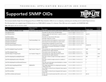
T E C H N I C A LA P P L I C A T I O NB U L L E T I N# 9 5 - 3 5 6 5Supported SNMP OIDsThis document identifies Simple Network Management Protocol (SNMP) Object Identifiers (OIDs) for use in configuring, monitoring and controlling network-enabled Tripp Lite devices.The following charts were compiled using LX Platform devices (e.g. WEBCARDLX) running 15.5.x firmware. These OIDs may not be compatible with SNMPWEBCARD.Note: OID support will vary by device model.NameATS -- TRIPPLITE-PRODUCTS MIBName in Interface(web/menu)DescriptionOIDSample OutputThis section shows indexed items: Two input sources and two outlets (loads). Additional outlets would be indexed in a similar manner.tlpATSBreakerIndexThe table row index for the ATS bank TSBreakerStatusIndicates whether the bank breaker is open(0), closed(1)or not n (0)tlpATSCircuitIndexThe table row index for the ATS TSCircuitInputVoltageThe input voltage for a TSCircuitTotalCurrentActualValueTotal Current Bank 1 (A)tlpATSCircuitTotalPowerThe total current for all receptacles in a given circuit.1.3.6.1.4.1.850.1.1.3.4.3.4.1.1.4.1.x0The total power for all receptacles in a given TSCircuitUtilizationThe percentage of utilization of a given ATSConfigAutoShedOnTransitionIf enabled(1), the ATS will perform its preconfiguredshed sequence on transfer from primary to secondaryinput source.1.3.6.1.4.1.850.1.1.3.4.5.1.1.6.1disabled (0)High Transfer Voltage (V)The maximum line voltage allowed before the unitdisconnects the AC input The nominal value of the input line voltage.1.3.6.1.4.1.850.1.1.3.4.5.1.1.1.1230Low Transfer Voltage (V)The minimum line voltage allowed before the unitdisconnects the AC input 144.0tlpATSConfigOutputCurrentHighThresholdThe value at which an output current high condition 0.0tlpATSConfigOutputCurrentLowThresholdThe value at which an output current low condition ATSConfigOutputCurrentThresholdToleranceThe value used with output current thresholds to evaluateoutput current conditions.1.3.6.1.4.1.850.1.1.3.4.5.6.1.2.1.12The voltage range options for configuring the operatingvoltages of an ldTableOBSOLETEtlpATSControlRampSet to TRUE to initiate the pre-designated ramp sequence .1.3.6.1.4.1.850.1.1.3.4.4.1.1.1.1on the ATS.0tlpATSControlShedSet to TRUE to initiate the pre-designated shed sequenceon the MainLoadCommandSet this value to turn the main load off(1), on(2) or cycle(3); idle (0).1.3.6.1.4.1.850.1.1.3.4.2.1.1.3.1idle (0)266.0
NameName in tPrecisionOutput Current PrecisionDescriptionOIDSample OutputIndicates whether the main output is controllable/if theUPS can be turned off and on.1.3.6.1.4.1.850.1.1.3.4.2.1.1.2.1true (1)The current state of the main output of the device.1.3.6.1.4.1.850.1.1.3.4.2.1.1.1.1The measurement precision--use as a divisor to obtain the .1.3.6.1.4.1.850.1.1.3.4.2.1.1.11.1true output current.on (2)hundredths (2)tlpATSDeviceOutputPowerTotalThe AC output total power for all evicePowerOnDelayThe amount of time a given device will wait before itconnects to a valid AC iceTotalInputPowerRatingThe total input power rating of all phases on the IdentNumATSThe number of ATS devices that this agent is pATSIdentNumBreakersThe number of bank breakers supported by the umCircuitsThe number of circuits supported by the umHeATSinksThe number of heatsink thermistors supported by ntNumInputsThe number of inputs supported by the umOutletgroupsThe number of receptacle groups supported by the umOutletsThe number of receptacles supported by the NumOutputsThe number of outputs supported by the umPhasesNumber of PhasesActualValueThe number of phases per input supported by the adTransferVoltageThe minimum line voltage allowed before the unitdisconnects the AC input lpATSInputCurrentLimitThe capacity of each phase conductor, limited by the ACinput cord or other TSInputHighTransferVoltageThe maximum line voltage allowed before the unitdisconnects the AC input tlpATSInputLineIndex.1.1.1The table row index for the input line on the InputLineIndex.1.1.2Same description as 075.0139.0tlpATSInputNominalVoltage.1The nominal value of the input line TSInputNominalVoltagePhaseToPhaseThe nominal value of the input line voltage as measuredfrom phase to .059.9tlpATSInputPhaseFrequency.1.1.1Input Frequency 1 (Hz)The present input frequency for a given pATSInputPhaseFrequency.1.1.2Input Frequency 2 (Hz)Same description as TSInputPhaseIndex.1.1.1The table row index for the input phase for the input SInputPhaseIndex.1.1.2Same description as TSInputPhaseVoltage.1.1.1Input Voltage 1 (V)The magnitude of the present input voltage for a 2470Same description as above.tlpATSInputPhaseVoltage.1.1.2Input Voltage 2 InputPhaseVoltageMax.1.1.1Maximum Input Voltage (V) The maximum input voltage value since the last reset ofthis value for a given lpATSInputPhaseVoltageMin.1.1.1The minimum input voltage value since the last reset ofthis value for a given phase.1.3.6.1.4.1.850.1.1.3.4.3.1.2.1.6.1.1.10The determination as to which of two AC input lines nputSourceA (1)Indicates on which bank the given outlet is put Source Available247.0257.0
NameName in Interface(web/menu)DescriptionOIDSample OutputtlpATSOutletBank.1.2Same description as SOutletCircuit.1.1Indicates on which circuit the given outlet is SOutletCircuit.1.2Same description as SOutletCommand.1.1Set this value to turn the outlet off(1), on(2) or cycle (3);idle (0).1.3.6.1.4.1.850.1.1.3.4.3.3.1.1.6.1.1idle (0)tlpATSOutletCommand.1.2Same description as above.1.3.6.1.4.1.850.1.1.3.4.3.3.1.1.6.1.2idle (0)tlpATSOutletControllable.1.1Denotes whether this outlet is true (1)true (1)tlpATSOutletControllable.1.2Same description as utletDescription.1.1A user-definable string identifying the device(s)connected to the given OutletDescription.1.2Same description as utletGroup.1.1The table row index for the ATS outlet SOutletGroup.1.2Same description as SOutletIndex.1.1The table row index for the ATS SOutletIndex.1.2Same description as OutletName.1.1A user-definable string identifying the name of the lpATSOutletName.1.2Same description as pATSOutletPhase.1.1Indicates on which phase or phases the given outlet 1phase1 (1)tlpATSOutletPhase.1.2Same description as above.1.3.6.1.4.1.850.1.1.3.4.3.3.1.1.17.1.2phase1 (1)tlpATSOutletRampAction.1.1The ramp action to take on a given outlet when poweringon the nOff (0)tlpATSOutletRampAction.1.2Same description as Off (0)tlpATSOutletRampDelay.1.1The number of seconds to delay before powering on thegiven TSOutletRampDelay.1.2Same description as SOutletShedAction.1.1The shed action to take on a given outlet when poweringoff the nOn (0)tlpATSOutletShedAction.1.2Same description as On (0)tlpATSOutletShedDelay.1.1The number of seconds to delay before powering off thegiven TSOutletShedDelay.1.2Same description as SOutletState.1.1The current state of the outlet.1.3.6.1.4.1.850.1.1.3.4.3.3.1.1.4.1.1on (2)tlpATSOutletState.1.2Same description as above.1.3.6.1.4.1.850.1.1.3.4.3.3.1.1.4.1.2on (2)The output current, in hundreths of amps, for a aximum Output Current (A) The maximum current observed for a given phase sincelast reset.1.3.6.1.4.1.850.1.1.3.4.3.2.1.1.7.1.10The minimum current observed for a given phase sincelast OutputCurrentOutput Current MintlpATSOutputFrequencyOutput Frequency eIndexOutput Voltage (V)The present output e table row index for the ATS phase.1.3.6.1.4.1.850.1.1.3.4.3.2.1.1.1.1.11The magnitude of the present output voltage for a givenoutput line.1.3.6.1.4.1.850.1.1.3.4.3.2.1.1.4.1.12472The table row index for the ATS lue247.2
NameName in Interface(web/menu)DescriptionOIDSample OutputtlpATSSupportsEnergywiseIndicates whether the ATS supports Cisco EnergyWise.1.3.6.1.4.1.850.1.1.3.4.1.3.1.1.1true (1)tlpATSSupportsOutletCurrentPowerIndicates whether the ATS reports individual receptaclecurrent and power e (2)tlpATSSupportsOutletGroupIndicates whether the ATS supports outlet groups.1.3.6.1.4.1.850.1.1.3.4.1.3.1.3.1true (1)tlpATSSupportsOutletVoltageIndicates whether the ATS reports individual receptaclevoltage e (2)tlpATSSupportsRampShedIndicates whether the ATS supports ramping andshedding.1.3.6.1.4.1.850.1.1.3.4.1.3.1.2.1true (1)ActualValueCooling -- TRIPPLITE-PRODUCTS MIBtlpCoolingAmbientDegF.1Ambient Temperature oolingDefrostModeDefrost This option enables or disables the auto fan speed.1.3.6.1.4.1.850.1.1.3.5.5.1.1.25.1enabled (1)This option enables or disables the defrost mode.1.3.6.1.4.1.850.1.1.3.5.5.1.1.19.1disabled (0)Specifies whether displays output values in Metric orEnglish form ATS.1.3.6.1.4.1.850.1.1.3.5.5.1.1.4.1english (1).1.3.6.1.4.1.850.1.1.3.5.5.1.1.18.1energySaving (1)Evaporator Temperature (F) The temperature of the evaporator surface in tenthsdegrees FahrenheitThis option enables or disables the energy saving mode.1.3.6.1.4.1.850.1.1.3.5.3.1.1.1.5.148048.0The temperature of the evaporator surface in tenthsdegrees ngHotGasBypassThe ambient temperature in tenths degrees Fahrenheit.The ambient temperature in tenths degrees Celsius.Hot Gas BypasstlpCoolingIdentNumCoolingSpecifies the actual speed of the evaporator fan.1.3.6.1.4.1.850.1.1.3.5.5.1.1.2.1high (5)This option enables or disables the hot gas bypass.1.3.6.1.4.1.850.1.1.3.5.5.1.1.24.1disabled (0)The number of cooling devices that this agent is currently nOff1Turn the unit on or off.1.3.6.1.4.1.850.1.1.3.5.4.1.1.1.1turnOnUnit (1)The current operating mode.1.3.6.1.4.1.850.1.1.3.5.3.6.1.1.1cooling (2)tlpCoolingRemoteTemperatureSensorThis option enables or disables the remote .1enabled (1)tlpCoolingSetPointDegF.1The set point temperature the unit will control in tenthsdegrees 0tlpCoolingSetPointDegCThe set point temperature the unit will control in tenthsdegrees e current water status of cooling unit.1.3.6.1.4.1.850.1.1.3.5.3.6.1.5.1notFull (0)tlpCoolingOperatingModeOperating ModetlpCoolingWaterStatusWater StatusDevice -- TRIPPLITE-PRODUCTS MIBThis section shows indexed items: A host device with one sensor. Up to two additional sensor would be indexed in a similar manner.tlpDeviceID.1A user-supplied ID for the tCommPortName.1The name of the communications iceIdentCommPortName.2Same description as above.1.3.6.1.4.1.850.1.1.2.1.1.3.2/dev/serial tlpDeviceIdentCommPortType.1The type of communications port used to connect withthe device.1.3.6.1.4.1.850.1.1.2.1.1.2.1serial ntUptimetlpDeviceIdentDateInstalled.1Current Uptime (Hours)Same description as above.1.3.6.1.4.1.850.1.1.2.1.1.2.2serial (1)The device uptime since its last startup.1.3.6.1.4.1.850.1.1.2.1.1.8.1463The installation date for this device in the format of mm/dd/yyyy.1.3.6.1.4.1.850.1.1.2.1.1.6.19/27/2018
NameName in Interface(web/menu)DescriptionOIDSample OutputtlpDeviceIdentDateInstalled.2Same description as viceIdentFirmwareVersion.1The firmware version of the ntProtocol.1The Tripplite protocol used to communicate with ceIdentProtocol.2Same description as entSerialNum.1The serial number of the 0076tlpDeviceIdentSerialNum.2Same description as 010tlpDeviceIndex.1The table row index for the x.2tlpDeviceIdentTotalUptimeTotal Uptime (Days)Same description as above.1.3.6.1.4.1.850.1.1.1.2.1.1.22The cumulative (total) uptime for the cation.1A user-supplied location for the device.1.3.6.1.4.1.850.1.1.1.2.1.8.1Room 4BtlpDeviceLocation.2Same description as above.1.3.6.1.4.1.850.1.1.1.2.1.8.2Room 4BtlpDeviceManufacturer.1The name of the EtlpDeviceManufacturer.2Same description as above.1.3.6.1.4.1.850.1.1.1.2.1.4.2TRIPP LITEtlpDeviceModel.1The model 3UPMtlpDeviceModel.2Same description as Name.1A user-supplied name for the eviceName.2Same description as viceNumDevices.0The number of devices that this agent is iceRegion.1A user-supplied region for the ceRegion.2Same description as eRowStatus.1Used with table edits to indicate the status of a given row. .1.3.6.1.4.1.850.1.1.1.2.1.2.1active (1)tlpDeviceRowStatus.2Same description as above.active The currently most critical alarm status for the device.1.3.6.1.4.1.850.1.1.1.2.1.10.1none (0)tlpDeviceStatus.2Same description as above.1.3.6.1.4.1.850.1.1.1.2.1.10.2none (0)tlpDeviceType.1The type of device. One of the appropriate hardwaretypes: UPS, PDU, EnviroSense, pe.2Same description as nviro Sensor -- TRIPPLITE-PRODUCTS MIBThis section shows indexed items: Two sensors. One additional sensor would be indexed in a similar dity.3Humidity (%)The upper alarm limit for ambient humidity.1.3.6.1.4.1.850.1.1.3.3.5.1.1.4.345The ambient humidity.1.3.6.1.4.1.850.1.1.3.3.3.2.1.1.337false (2)tlpEnvHumidityInAlarm.3Indicates whether or not humidity is in ityLowLimit.3The lower alarm limit for ambient dentHumiditySupported.2Indicates whether or not humidity is supported.1.3.6.1.4.1.850.1.1.3.3.1.2.1.2.2false (2)tlpEnvIdentHumiditySupported.3Same description as above.1.3.6.1.4.1.850.1.1.3.3.1.2.1.2.3true (1)tlpEnvIdentNumEnviroSense.0The number of EnviroSense devices that this agent iscurrently TempSupported.2Indicates whether or not temperature is supported.1.3.6.1.4.1.850.1.1.3.3.1.2.1.1.2true (1)tlpEnvIdentTempSupported.3Same description as above.1.3.6.1.4.1.850.1.1.3.3.1.2.1.1.3true (1)tlpEnvInputContactCurrentState.3.1The current state of the contact.1.3.6.1.4.1.850.1.1.3.3.3.3.1.4.3.1open (0)tlpEnvInputContactCurrentState.3.2Same description as above.1.3.6.1.4.1.850.1.1.3.3.3.3.1.4.3.2open (0)ActualValue
NameName in Interface(web/menu)DescriptionOIDSample OutputtlpEnvInputContactInAlarm.3.1Indicates whether or not the contact is in alarm.1.3.6.1.4.1.850.1.1.3.3.3.3.1.5.3.1false (2)tlpEnvInputContactInAlarm.3.2Same description as above.1.3.6.1.4.1.850.1.1.3.3.3.3.1.5.3.2false (2)tlpEnvInputContactIndex.3.1The table row index for the EnviroSense input .3.1Contact Input 1tlpEnvInputContactName.3.2Contact Input 1tlpEnvInputContactNormalState.3.1Same description as above.1.3.6.1.4.1.850.1.1.3.3.3.3.1.1.3.22The name or description of the contact.1.3.6.1.4.1.850.1.1.3.3.3.3.1.2.3.1Contact Input #1Same description as above.1.3.6.1.4.1.850.1.1.3.3.3.3.1.2.3.2Contact Input #2The normal operating position of the contact.1.3.6.1.4.1.850.1.1.3.3.3.3.1.3.3.1open (0)tlpEnvInputContactNormalState.3.2Same description as above.1.3.6.1.4.1.850.1.1.3.3.3.3.1.3.3.2open (0)tlpEnvNumInputContacts.2The number of input contacts supported by lpEnvNumInputContacts.3Same description as utputContacts.2The number of output contacts supported by State.2.1Contact Output 1Same description as above.1.3.6.1.4.1.850.1.1.3.3.1.2.1.4.30The current state of the contact.1.3.6.1.4.1.850.1.1.3.3.3.4.1.4.2.1open (0)tlpEnvOutputContactCurrentState.2.2Contact Output 2Same description as above.1.3.6.1.4.1.850.1.1.3.3.3.4.1.4.2.2open (0)tlpEnvOutputContactCurrentState.4.1Contact Output 1Same description as above.1.3.6.1.4.1.850.1.1.3.3.3.4.1.4.4.1open (0)tlpEnvOutputContactCurrentState.4.2Contact Output 2Same description as above.1.3.6.1.4.1.850.1.1.3.3.3.4.1.4.4.2open (0)tlpEnvOutputContactInAlarm.2.1Indicates whether or not the contact is in alarm.1.3.6.1.4.1.850.1.1.3.3.3.4.1.5.2.1false (2)tlpEnvOutputContactInAlarm.2.2Same description as above.1.3.6.1.4.1.850.1.1.3.3.3.4.1.5.2.2false (2)tlpEnvOutputContactInAlarm.4.1Same description as above.1.3.6.1.4.1.850.1.1.3.3.3.4.1.5.4.1false (2)tlpEnvOutputContactInAlarm.4.2Same description as above.1.3.6.1.4.1.850.1.1.3.3.3.4.1.5.4.2false (2)tlpEnvOutputContactIndex.2.1The table row index for the EnviroSense output 1tlpEnvOutputContactIndex.2.2Same description as tputContactIndex.4.1Same description as tputContactIndex.4.2Same description as tputContactName.2.1The name or description of the contact.1.3.6.1.4.1.850.1.1.3.3.3.4.1.2.2.1Contact Output #1tlpEnvOutputContactName.2.2Same description as above.1.3.6.1.4.1.850.1.1.3.3.3.4.1.2.2.2Contact Output #2tlpEnvOutputContactName.4.1Same description as above.1.3.6.1.4.1.850.1.1.3.3.3.4.1.2.4.1Contact Output #1Contact Output #2tlpEnvOutputContactName.4.2Same description as putContactNormalState.2.1The normal operating position of the contact.1.3.6.1.4.1.850.1.1.3.3.3.4.1.3.2.1open (0)tlpEnvOutputContactNormalState.2.2Same description as above.1.3.6.1.4.1.850.1.1.3.3.3.4.1.3.2.2open (0)tlpEnvOutputContactNormalState.4.1Same description as above.1.3.6.1.4.1.850.1.1.3.3.3.4.1.3.4.1open (0)tlpEnvOutputContactNormalState.4.2Same description as above.1.3.6.1.4.1.850.1.1.3.3.3.4.1.3.4.2open (0)ActualValuetlpEnvTemperatureC.2Temperature The ambient temperature, in degrees pEnvTemperatureC.3Temperature Same description as nvTemperatureF.2Temperature (F)The ambient temperature, in degrees 1tlpEnvTemperatureF.3Temperature (F)Same description as nvTemperatureHighLimit.2The upper alarm limit for ambient EnvTemperatureHighLimit.3Same description as peratureInAlarm.2Indicates whether or not temperature is in alarm.1.3.6.1.4.1.850.1.1.3.3.3.1.1.3.2false (2)
NameName in Interface(web/menu)DescriptionOIDSample OutputtlpEnvTemperatureInAlarm.3Same description as above.1.3.6.1.4.1.850.1.1.3.3.3.1.1.3.3false (2)tlpEnvTemperatureLowLimit.2The lower alarm limit for ambient EnvTemperatureLowLimit.3Same description as above.1.3.6.1.4.1.850.1.1.3.3.5.1.1.1.365PDU -- TRIPPLITE-PRODUCTS MIBThis section shows indexed items: three phases, 2 outlets and 2 outlet groups. The remaining outlets and additional outlet groups would be indexed in a similar manner.tlpPDUBreakerIndex.1.1The table row index for the PDU bank DUBreakerIndex.1.2Same description as Bank Breaker 1 StatusSame description as tes whether the bank breaker is open(0), closed(1)or not installed (2).1.3.6.1.4.1.850.1.1.3.2.3.5.1.1.2.1.1closed (1)tlpPDUBreakerStatus.1.2Bank Breaker 2 StatusSame description as above.1.3.6.1.4.1.850.1.1.3.2.3.5.1.1.2.1.2closed (1)tlpPDUBreakerStatus.1.3Bank Breaker 3 StatusSame description as above.1.3.6.1.4.1.850.1.1.3.2.3.5.1.1.2.1.3closed (1)tlpPDUCircuitIndex.1.1The table row index for the PDU DUCircuitIndex.1.2Same description as above.1.3.6.1.4.1.850.1.1.3.2.3.4.1.1.1.1.22Same description as CircuitInputVoltage.1.1tlpPDUCircuitIndex.1.3Input Voltage Bank 1 (V)The input voltage for a 13.6tlpPDUCircuitInputVoltage.1.2Input Voltage Bank 2 (V)Same description as .0213.0tlpPDUCircuitInputVoltage.1.3Input Voltage Bank 3 (V)Same description as PDUCircuitTotalCurrent.1.1Total Current Bank 1 (A)The total current for all receptacles in a given DUCircuitTotalCurrent.1.2Total Current Bank 2 (A)Same description as CircuitTotalCurrent.1.3Total Current Bank 3 (A)Same description as CircuitTotalPower.1.1Total Power Bank 1 (W)The total power for all receptacles in a given DUCircuitTotalPower.1.2Total Power Bank 2 (W)Same description as CircuitTotalPower.1.3Total Power Bank 3 (W)Same description as CircuitUtilization.1.1Total Current Bank 1 (%)The percentage of utilization of a given PDUCircuitUtilization.1.2Total Current Bank 2 (%)Same description as UCircuitUtilization.1.3Total Current Bank 3 (%)Same description as UConfigInputVoltageThe nominal value of the input line ConfigOutputCurrentHighThreshold.1.1The value at which an output current high condition 0.0tlpPDUConfigOutputCurrentHighThreshold.1.2Same description as pPDUConfigOutputCurrentHighThreshold.1.3Same description as pPDUConfigOutputCurrentLowThreshold.1.1The value at which an output current low condition PDUConfigOutputCurrentLowThreshold.1.2Same description as nfigOutputCurrentLowThreshold.1.3Same description as nfigOutputCurrentThresholdTolerance.1.1The value used with output current thresholds to evaluateoutput current PDUConfigOutputCurrentThresholdTolerance.1.2Same description as nfigOutputCurrentThresholdTolerance.1.3Same description as ntrolRampSet to TRUE to initiate the pre-designated ramp sequence .1.3.6.1.4.1.850.1.1.3.2.4.1.1.1.1on the PDU.0tlpPDUControlShedSet to TRUE to initiate the pre-designated shed sequenceon the PDU.0.1.3.6.1.4.1.850.1.1.3.2.4.1.1.2.1
NameName in Interface(web/menu)DescriptionOIDSample OutputtlpPDUDeviceMainLoadCommandSet this value to turn the main load off(1), on(2) or cycle(3); idle (0).1.3.6.1.4.1.850.1.1.3.2.2.1.1.3.1idle (0)tlpPDUDeviceMainLoadControllableIndicates whether the main output is controllable/if theUPS can be turned off and on.1.3.6.1.4.1.850.1.1.3.2.2.1.1.2.1true (1)tlpPDUDeviceMainLoadStateThe current state of the main output of the ceOutputCurrentPrecisionThe measurement precision--use as a divisor to obtain the .1.3.6.1.4.1.850.1.1.3.2.2.1.1.11.1true output aseImbalance.1Phase Imbalance (%)tlpPDUDevicePowerOnDelayon (2)hundredths (2)The AC output total power for all circuits.1.3.6.1.4.1.850.1.1.3.2.2.1.1.9.10The percentage of imbalance of the three phases.1.3.6.1.4.1.850.1.1.3.2.2.1.1.8.10The amount time a given device will wait before itconnects to a valid AC iceTotalInputPowerRatingThe total input power rating of all phases on the DisplayScheme.1Indicates the display scheme of the LED mal (1)tlpPDUDisplayUnits.1Indicates the units of measurement displayed on the LEDdisplay.1.3.6.1.4.1.850.1.1.3.2.1.4.1.5.1normal (0)tlpPDUIdentNumBreakersThe number of monitored bank breakers supported by ntNumCircuitsThe number of circuits supported by the umHeATSinksThe number of heatsink thermistors supported by ntNumInputsThe number of input lines supported by the umOutletgroupsThe number of receptacle groups supported by the umOutletsThe number of receptacles supported by the NumOutputsThe number of output lines supported by the umPDUThe number of PDU devices that this agent is currentlymanagin
Supported SNMP OIDs. This document identifies Simple Network Management Protocol (SNMP) Object Identifiers (OIDs) for use in configuring, monitoring and controlling network-enabled Tripp Lite devices.