Transcription
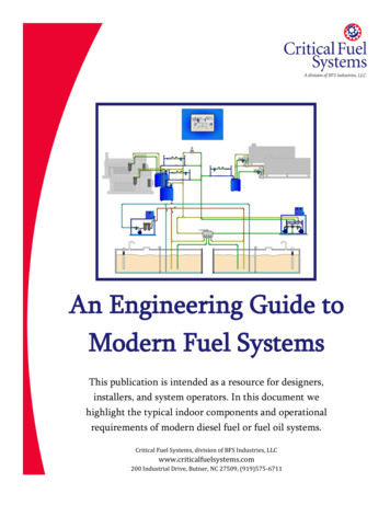
Forced air mobile diesel heating systems.
Section 1: Location Find a location for the stove/heater.1.2.3.4. 2020 Two Mac Inc.The stove should be mounted in a counter, higher than the fuel andwithin the 10’ exhaust run limit.There needs to be at least 16 square inches of under counterventilation for the combustion and heating fans.Counter can be made of laminates, composites, wood, stone, etc.Not compatible with Starboard .Can be mounted parallel to keel or athwartships.2
Section 1: Location Cut out countertop:Total devicefootprint with lidup is 14.5” deepby 19” wide,includingpotholders.Allow 8” of depthbelow countertop. 2020 Two Mac Inc.3
Safety note: Every boat or vehicle equipped with any kind of petroleum fueled engine or device should also be equippedwith a CO (carbon monoxide) detector.1.2.Detector should be capable of independent function.Detector should be tested for correct operation regularly, replaced on schedule. 2020 Two Mac Inc.4
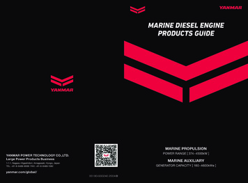
Section 2: Exhaust Outlet Find a place for the exhaust through hull or house.1.2.3.4.5.6.7.8.Within 10’ exhaust run limits.Not facing the direction of travel.Aft of the widest point of the beam.Not on back of house to prevent “station wagon” effect.Allowing for 12” loop or rise inside the hull or house.14” or more above the waterline.Aluminum boats should use a through hull isolation kit.For fittings in deck or roof, contact Wallas supplier. 2020 Two Mac IncSee Figure 1.5
Figure 1: Exhaust locationsNote: Avoid placingexhaust outlet wherefenders will hang! 2020 Two Mac Inc6
Figure 1S: Sailboat exhaust outlet locationsNote: Avoid placingexhaust outlet wherefenders will hang! 2020 Two Mac Inc.7
Section 3: Exhaust System Make the exhaust run. See the descriptions in figure 2.1.2.3. 2020 Two Mac Inc.Exhaust can run to a point higher, lower or at the same level asthe stove.Always have a 12” loop or rise at the hull side, so any water thatenters the fitting runs right back out.a)Prevent water from entering exhaust outlet and remaining inthe exhaust pipe (prevents running or system will run poorly).b)Prevent water from entering stove (system failure).Do not allow exhaust hose to lean against soft plastics, fuel line,electronics or wiring.8
Figure 2: Exhaust routings 2020 Two Mac Inc9
Section 4: Fuel connections Make fuel connection.1.If using a Wallas supplied day tank, just connect the parts,shorten the fuel line from the filter end as appropriate tothe installation, and attach the tank appropriately toprevent it moving.2.If using a dedicated day tank from others, verify it is a topof tank pickup, use a Wallas filter and fuel line only. If thetank pickup ends in a ¼” hose barb, this will makeconnections easy. 2020 Two Mac Inc.10
Section 4: Fuel connectionsIf taking fuel from the main tank or ashared tank, assure the Wallas devicehas its own pickup.3.a)b) 2015 Two Mac Inc.You can use a #50011 custom droptube to match an existing femalefitting, or adapt to a breather fitting,or use a #30011 drop tube to make anew penetration into the top of thetank.11
Section 4: Fuel connectionsWhen connecting the fuel line to thefuel pump, ALWAYS hold the fuelpump elbow steady with a ViceGrip or equivalent and use a 12 mm endwrench to tighten the fuel nut to theelbow VERY TIGHT. This will assureno air leaks. Do NOT turn the elbowrelative to the pump body, as thiscan damage the pump metering,ruining the pump. 2015 Two Mac Inc.12
Section 5: Electrical connections The Wallas power supply should be fuse or breaker protected to 15 amps.The system will arrive with 13’ of 11 GA wire. If this is long enough to reach thebattery or main bus, it should be large enough to carry the starting amperage tostart the stove.Longer wire runs WILL require larger wire gauge:1.2.a)b)c)3.4. 2015 Two Mac Inc.Up to 15’ : 10GAUp to 18’ : 8GAUp to 22’ : 6GAWhen testing the stove, a flashing yellow panel light indicates low voltage, possiblypower lead drop due to undersized or power leads too long for their size.The stove should always be shut off using the control panel. Do not drop the powersupply while the stove is running.13
Section 6: Mounting the control panel The Wallas Nordic Dtcontrol panel comes with a6’ wire harness The panel should bemounted in a verticalsurface, not on the countertop.The Nordic Dt uses a thermo control panel, capableof sensing room temperature & controlling output powerautomatically when in heating mode. Panel locationshould be made accordingly. 2020 Two Mac Inc.14
Section 7: Lockout feature The Wallas Nordic Dt has a lockout feature that locks the system up if ithas failed to start on two consecutive tries. On the third try, both theyellow and red panel lights will flash rapidly. To clear lockout:1.Leave panel on, with both the red flame and yellow power lightsflashing. They will flash for five minutes.2.While lights are flashing, kill power to the unit at its source: Pull the plug, remove the fuse or turn off breaker.3.Return power to the unit: Reconnect the plug, replace the fuse or turn on breaker.4.Wait five seconds, push control button for three seconds tocompletely shut system off.5.Stove is ready to start again, but before you do, investigate thesystem to figure out why it has not been starting successfully:fuel, power, glow plug failure, etc. 2020 Two Mac Inc.RedflamelightYellowpowerlight15
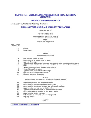
Section 8: Cabinet ventilation. The Wallas Nordic Dt has two fan motors, one to feed thecombustion process and one to blow air across the stove topinto the cabin for heating. Every installation of this stove/heater MUST provideadequate under counter ventilation! Ideally, a minimum of 16 square inches of inlet areamust be available for cooling and combustion air.See Figure 3 2020 Two Mac Inc.16
Figure 3: Inlet airCabinetventilation 2020 Two Mac Inc.17
Figure 4: Stove Reference 2020 Two Mac Inc.18
Figure 5: Stove Reference 2015 Two Mac Inc.19
Figure 6: Stove Reference 2015 Two Mac Inc.20
Thank you! 2020 Two Mac Inc.21
The Wallas Nordic Dt has two fan motors, one to feed the combustion process and one to blow air across the stove top into the cabin for heating. Every installation of this stove/heater MUST provide adequate under counter ventilation! Ideally, a minimum of 16 square inches of inlet area must be available for cooling and combustion air.