Transcription
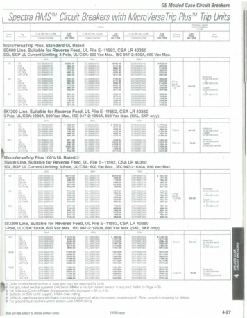
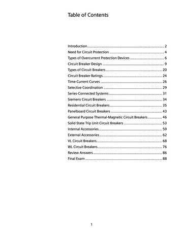
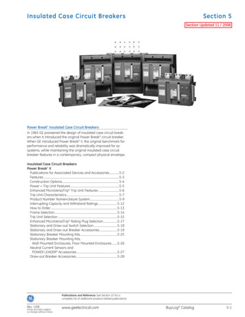
Insulated Case Circuit BreakersSection 5Section Updated 11 / 2008Power Break Insulated Case Circuit BreakersIn 1965 GE pioneered the design of insulated case circuit breakers when it introduced the original Power Break circuit breaker.When GE introduced Power Break II, the original benchmark forperformance and reliability was dramatically improved for acsystems, while maintaining the original insulated case circuitbreaker features in a contemporary, compact physical envelope.Insulated Case Circuit BreakersPower Break IIPublications for Associated Devices and Accessories.5-2Features .5-3Construction Options.5-4Power Trip Unit Features .5-5Enhanced MicroVersaTrip Trip Unit Features .5-6Trip Unit Characteristics.5-7Product Number Nomenclature System.5-9Interrupting Capacity and Withstand Ratings.5-12How to Order .5-13Frame Selection.5-14Trip Unit Selection .5-15Enhanced MicroVersaTrip Rating Plug Selection.5-17Stationary and Draw-out Switch Selection.5-18Stationary and Draw-out Breaker Accessories.5-19Stationary Breaker Mounting Kits.5-25Stationary Breaker Mounting Kits,Wall Mounted Enclosures, Floor Mounted Enclosures.5-26Neutral Current Sensors andPOWER LEADER Accessories.5-27Draw-out Breaker Accessories.5-28Publications and Reference: See Section 22 for acomplete list of additional product-related publicationsRev. 1/08Prices and data subjectto change without noticewww.geelectrical.comBuyLog Catalog5-1
Insulated Case Circuit BreakersSection 5Publications for Associated Devices and AccessoriesUL/CSA File NumbersPower Break Breakers.E11592/LR10263MicroVersaTrip Plus and MicroVersaTrip PMand Power Trip Units.E11592/LR10263MicroVersaTrip and Power Rating Plugs .E11592/LR10263Accessories.E57253/LR10263Molded Case Switches.E57546/LR16271Power Break II Time Current Curve-NumbersFunctionsEnhanced MicroVersaTripPlus and MicroVersaTripPM Trip UnitsCurve No.Long-time Delay with InstantaneousorLong-time Delay, Short-time Delaywith InstantaneousGES-9889Ground FaultGES-9890Power Break II Circuit Breaker Accessories–Draw-Out Substructure Rail Kit.GEH-6440Walking Beam Interlock 800A, 1600A, 2000A .GEH-6286Walking Beam Interlock 2500-3000A.DEH-009Walking Beam Interlock 4000A .DEH-010Draw Out Mechanical Interlock 800-2000A .DEH-011Draw Out Mechanical Interlock 2500-4000A.DEH-012Neutral Kit .DEH-024Hidden “ON” Button.DEH-025High Voltage Shunt Trip.GEH-6519High Voltage Under Voltage Release .GEH-6520Under Voltage Release Time Delay Relay .GEJ-4699Power Break II Circuit Breakers Trip UnitsPower Trip Unit.DEH-049Power Break II Instructions for Breakers and AccessoriesPower Break II Circuit Breakers–800-4000 A frames, 240-600 Vac.GEH-6270Power Break II Circuit Breakers–Draw-Out 800-4000 Ampere Frames .GEH-6271Power Break II Circuit Breakers–Draw-Out Substructure.GEH-6272Power Break II Circuit Breakers–Trip Unit.GEH-6273Power Break II Circuit Breaker Accessories–Auxiliary Switch Module.GEH-6274Power Break II Circuit Breaker Accessories–Bell Alarm-Alarm Only .GEH-6275Power Break II Circuit Breaker Accessories–Door Interlock .GEH-6276Power Break II Circuit Breaker Accessories–Lug Kits and T Studs .GEH-4546Power Break II Circuit Breaker Accessories–Bell Alarm with Lockout .GEH-6278Power Break II Circuit Breaker Accessories–Key Interlock Provision .GEH-6279Power Break II Circuit Breaker Accessories–Mechanical Counter .GEH-6280Power Break II Circuit Breaker Accessories–Motor Operator Mechanism .GEH-6281Power Break II Circuit Breaker Accessories–Push Button Cover.GEH-6282Power Break II Circuit Breaker Accessories–Remote Close.GEH-6283Power Break II Circuit Breaker Accessories–Shunt Trip.GEH-6284Power Break II Circuit Breaker Accessories–Undervoltage Release .GEH-6285Power Break II Circuit Breaker Accessories–Walking-Beam Interlock.GEH-6286TVRMS2 Test Kit.GEK-97367Power Break II Circuit Breaker Accessories–Draw-Out Substructure Secondary Disconnect.GEH-64605-2BuyLog CatalogPower Break II Circuit BreakersRating Plugs.GEH-5933Enclosures 800-2000A.GEH-6503Power Break II Insulated Case Switches800-4000A, 240-600 Vac.DEH-40380Power Control Units.DEH-40381www.geelectrical.comRev. 1/08Prices and data subjectto change without notice
Insulated Case Circuit BreakersSection 5 Power Break II Circuit BreakersFeaturesPower Break II Circuit BreakersThe Insulated Case Circuit Breaker—GE pioneered the designand created the name in 1965. GE Power Break II insulated casecircuit breakers are the latest in reliable, flexible and easy-to-usecircuit protection.Power Break II circuit breakers are UL Listed, CSA and IEC-947-2Certified for up to 200,000 amperes, at 240 volts rms symmetricalinterrupting capacity without fuses or current limiters. These newinsulated case circuit breakers rated 200-4000A can be appliedon ac power systems through 600 volts. All breaker frames,except 4000A stationary, are UL Listed to carry 100% of theirampere rating continuously. All frames are suitable for reversefeeding.All Power Break II circuit breakers are available in two levelsof interrupting capacity—”standard break” and “Hi-Break”breakers. Each interrupting level is available in both stationaryand draw-out construction, with a full complement of controland signaling accessories.Standard break breakers are designed to meet the majority ofapplication requirements, calling for moderate levels of availableshort-circuit current.Hi-Break breakers are specially designed to withstand the stresses, and safely interrupt high levels of short-circuit current foundin some applications (from 65 to 200 kA rms symmetricalamperes—depending on voltage).Greater Convenience and Operational SafetyThe controls and status indicators you need most are readilyaccessible. The flush-mounted handle, ON/OFF buttons, ratingplug test receptacle, bell alarm reset buttons — with or withoutlockout — are easily reached and all are double-insulated fromlive components. And, for added security, a standard padlockdevice lets you prevent accidental or unauthorized closing ofthe breaker.Power Break II circuit breakers are versatile and designed fora wide variety of applications including temperature insensitivetrip units, push-to-open and close control, charge-after-closeoperation, 3 cycle closing, UL listed (file E 11592) field installableaccessories suitable for 50/60 Hz. All accessories and controlwiring are prewired to dedicated, secondary terminal points oneach breaker.Quick, Error-Free Installation of Universal AccessoriesDrop-in bell alarm, bell alarm with manual reset lockout, shunttrip, shunt trip with lockout, and undervoltage release install inseconds. No special tools. No breaker disassembly. Just slidethem into place. The modules are universal across all frame sizesand each is mechanically keyed to its compartment so you makethe right connection, every time. These accessories are fieldinstallable and upgradable.GE’s innovative, modular, drop-in accessories provide the ultimatecustomer solution for field customization:UL Listed—Accessory combination (one each) shunt trip, undervoltagerelease, bell alarm (alarm only), bell alarm with lockout.—Rated 12-250 Vdc through 12-240 Vac, continuous duty.Complete installation in seconds without special tools, breakerdisassembly or adjustment—The user can select how protective trip unit functions, theshunt trip (with or without lockout), and UVR accessoriesinterface with the bell alarm and bell alarm with lockoutaccessories: An overcurrent, shunt trip, or UVR trip canbe set to actuate the bell alarm or bell alarm with lockout.Any combination of output actions based on inputs canbe selected.—Shunt trip and undervoltage trip targets are clearly displayedby the trip unit LCD.Pre-wired wire harness makes field installation a snap for:—Motor operator with remote charge indicator—Auxiliary switches, up to 12-stage maximum—Remote close solenoidAdditional field-installable accessories including:—Kirk Key locks (4 maximum)—Limited access ON/OFF cover—Mechanical operations counter—Door interlock—Walking beam interlock for stationary and draw-out breakers.Ratings for Global Use—Performance ratings include IEC947-2 certification.Publications and Reference: See Section 22 for acomplete list of additional product-related publicationsRev. 1/08Prices and data subjectto change without noticewww.geelectrical.comBuyLog Catalog5-3
Insulated Case Circuit BreakersSection 5 Power Break IIConstruction OptionsThe interruption ratings and voltages shown in the table aremaximum ratings. A circuit breaker of the type given in the lefthand column may be applied at the given circuit voltage in anyelectrical distribution system where the available fault currentat the load terminals of the breaker does not exceed the valuein the table. That circuit breaker type may also be applied atintermediate values of circuit voltage provided the availablefault current at the load terminals of the breaker does notexceed the value in the table for the higher value of voltage.Insulated Case Circuit BreakersCircuit BreakerEnvelope Size(Amperes)Trip TypesPower MoldedMicroVersaTrip Plus/PMCase SwitchMax IC @480V (kA)Max VoltageRating (ac)Max 002000250030004000Power Break IIStandardHi-BreakMoldedCase 02000250030004000XXXXXXXXXXXXXXXXXXXXXXXXXX1Molded case switch ratings are short time @ 600Vac, not interrupting current. See page 5-12 for withstand ratings.5-4BuyLog Catalogwww.geelectrical.comRev. 1/08Prices and data subjectto change without notice
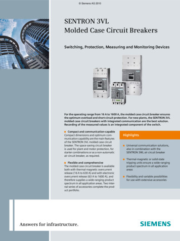
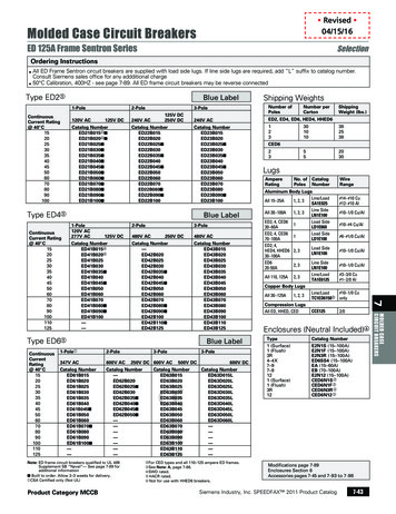
Insulated Case Circuit BreakersSection 5 Power Break II Circuit BreakersPower Trip Unit FeaturesPower Trip Unit SystemsTrip Target Module (Optional) The Power trip unit system for Power Break II insulated casebreakers consist of the trip unit, the trip actuator, current sensorsand rating plugs. The term “trip unit system” applies to the combination of these four components which form the solid-statecircuit breaker tripping system.Power trip units provide a complete range of standard andoptional overcurrent and ground-fault protective functions.True RMS SensingThe Power trip unit continues touse GE’s proven technique ofmeasuring true rms currents ofboth sinusoidal and harmonicallydistorted waveforms. The frequentsampling (48 times per cycle perphase) allows precise calculationsof true rms current. The samplingrate allows waveform measurements up to the 11th harmonic.GE’s true rms sensing avoidspotential underprotection or overprotection problems associatedwith peak-sensing tripping systems.Accessory IntegrationFour accessories are integrated through the Power trip unit.Drop-in shunt trip (with or without lockout), bell alarms (with orwithout lockout) and the undervoltage release modules fit intokeyed pockets. They operate through the trip units, and notthrough any external mechanisms. All accessory wiring is prewired to secondary terminals, and no user wiring is necessary.When activated, the shunt trip (with or without lockout) andundervoltage release modules send a signal to the trip unit toenergize the trip actuator and open the breaker.View Button: Press the VIEW button to check the trip unit status.Reset Button: Press the RESET button to clear any target that is set.Battery check: Target modules use two standard, 3V, 16mm x1.6mm, lithium batteries for viewing target information. Battery lifedepends upon use, but may be estimated at one year. When thebatteries are energized, depressing the VIEW button will illuminateeither a set target LED, i.e., LT or the BAT LED. Once target indicatorsare cleared, battery status is indicated by the BAT LED. Replacementbatteries include Panasonic CR1616, Eveready E-CR1616BP, orDuracell DL1616B, which may be purchased commercially.Long-time pickup: The long-time pickup indicator moves throughtwo transitions. As the current in any phase reaches 95% of itssetpoint; the LTPU LED begins to flash. As current increases,flashing frequency increases, until 100% of the pickup point isreached. At that moment, the LTPU LED stays on continuously untilthe long-time delay times out. Once the breaker has tripped onlong-time, the OVL target will be stored in memory. To view the trip,press the VIEW button. To clear the target, press the RESET button.Short-time and instantaneous trips: Short-time and instantaneoustrips share the same trip target. The LTPU LED is not illuminated,since the time intervals between pickup and tripping are too shortfor either function. Once the breaker has tripped on short-time orinstantaneous, the short target will be stored in memory. To view thetrip, press the VIEW button. To clear the target, press the RESET button.Ground fault trip (Target02 only): The trip target for a groundfault trip is the GF LED. To view the trip, press the view button. Toclear the target, press the RESET button.Health monitor: Trip unit health status “okay” is illustrated byslow blinking of the LTPU LED. It may be seen by depressing andholding the VIEW button. Sufficient power must be supplied to thetrip unit via external test kit, power pack, or current transformersfor the health monitor to be operational.Standard and Optional Protective FunctionsStandard and optional protective functions are available forPower trip units. The breaker settings are programmed in multiples of “X” (rating plug ampere values), “S” (current sensor ampererating values), and “C” (the long-time setting in amperes—multiplylong-time setting by rating plug ampere rating).Standard—Adjustable Long-Time (L) Pickup, 0.5 - 1.0X, with four delay bands.—Adjustable Instantaneous (I) Pickup, 1.5 - 15X.1OptionsPower Trip Target Module—Overload, Short Circuit, and Short-Time local trip indicators withoverload pickup warning and health monitor.—Adjustable Short-Time (S) Pickup, 1.5 - 9.0C, and delay (3 bands)with I2t ON/OFF selection.—Adjustable Ground Fault (G) Pickup, 0.2 - 0.6S, and delay1(3 bands) with I2t ON/OFF selection and trip indicator.—Upgradeable Ground Fault function with use of appropriateground fault rating plug.1Limited by breaker frame size above 2000A.Publications and Reference: See Section 22 for acomplete list of additional product-related publicationsRev. 1/08Prices and data subjectto change without noticewww.geelectrical.comBuyLog Catalog5-5
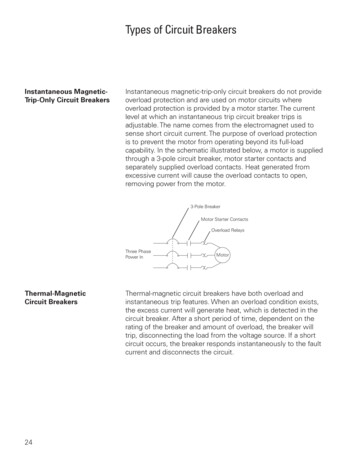
Insulated Case Circuit BreakersSection 5 Power Break II Circuit BreakersEnhanced MicroVersaTrip Trip Unit FeaturesEnhanced MicroVersaTrip Trip UnitsEnhanced MicroVersaTrip Plus and MicroVersaTrip PM trip unitsgive you two new ways to monitor and control the Power Break IIbreaker with unprecedented ease. Through the simple keypad,the trip unit lets you program and display a variety of functionsincluding tripping characteristics, remote communications, statusinformation and protective relaying, and allows integration withGE POWER LEADER Power Management Systems. The trip unitdisplay also allows viewing of many standard metering parameters as well as pickup alarms, trip target indications and faultstatus information.Enhanced MicroVersaTrip Plus and MicroVersaTrip PM tripunits continue to use GE’s proven technique of measuring truerms currents (and voltages for MicroVersaTrip PM trip units) ofboth sinusoidal and harmonically distorted waveforms. The frequent sampling (64 times per cycle) allows precise calculations oftrue rms current. The sampling rate allows waveform measurements up to the 31st harmonic to achieve accuracies of 99%.GE’s true rms sensing avoids potential underprotection or overprotection problems associated with peak-sensing tripping systems.Enhanced MicroVersaTrip Plus and MicroVersaTrip PM TripUnits have been specifically designed to integrate with theextensive capabilities offered by Power Break II circuit breakers.The enhanced trip unit design includes a wide range of functionsand adds many new features:UL Listed Field-InterchangeableFeatures exclusive to MicroVersaTrip PM Trip UnitsNon-volatile trip targets display/Cold setup capability—Replaceable long-life batteries provide trip target indicationsand cold setup capability—without the need for externalpower or a battery pack.Communications—All information can be viewed on the LCD display orcommunicated over a POWER LEADER PowerManagement System network.Trip operations counter—The number of long-time, short-time, instantaneous andground fault trips are individually counted and displayed.Demand/peak demand—The trip unit can display a rolling average of power demandand peak power demand at user-selected intervals from 5 to60 minutes.Trip information—On overcurrent faults, the trip unit displays fault pickup, thetype of fault, the magnitude of the fault current and thephase the fault occurred on.—Display indicates when a shunt trip or undervoltage releasetrip has opened the breaker.New display—Ergonomic, 5-button keypad—New targets with international symbols—High-resolution LCD display for local 3-phase ammetering—New status and setup displays for greater ease of use—True rms sensing for accurate response to high harmoniccontent waveforms for Long-Time, Short-Time, and GroundFault protection.—50/60 Hz operation.—Interchangeable, UL Listed trip units and rating plugs with testset jack for TVRMS2 test set.—EMI immunity per ANSI C37.90.5-6BuyLog CatalogLocal and remote metering—Amps, volts, frequency—Real power, total power—Accumulated energyProtective relays include:—Current and voltage unbalance—Overvoltage—Undervoltage—Power reversal—Power reversal direction setupwww.geelectrical.comRev. 1/08Prices and data subjectto change without notice
Insulated Case Circuit BreakersSection 5 Power Break II Circuit BreakersTrip Unit CharacteristicsPower Trip Unit CharacteristicsLong-TimeShort-TimeFrame Max.Ampere RatingSensor Rating(Amperes) (S)800200, 400, 8002.4, 4.9, 9.8, 2020001600800, 1000, 16002.4, 4.9, 9.8, 2030002500, 300040004000EnvelopeSize2000Current Setting (C) (Pick-Up)Multiple of Rating Plug Amperes (X)Delay1 (Seconds 4 Bands)0.5, 0.6, 0.7,0.8, 0.9, 0.95 and 1.020002.4, 4.9, 9.8, 201000, 2000, 2500, 3000Pick-up (Multipleof Current Setting) (C)Delay (Seconds 3 Bands)I2T in1.10, .21, .351.5, 2.0, 2.5, 3.0,4.0, 5.0, 7.0, and 9.0I2T out 2.10, .21, .352.4, 4.9, 9.8, 2040002.4, 4.9, 9.8, 20Power Trip Unit Characteristics (continued)Ground FaultEnvelope SizeAdjustable Instantaneous Pick-Up without ST(Multiple of Rating Plug Amperes) (X)2000Pick-Up (Multiple ofSensor Ampere Rating)Adjustable Instantaneous Pick-Up with ST(Multiple of Rating Plug Amperes) (X)1.5 thru 10.01.5 thru 15.00.20 thru 0.601.5 thru 10.01.5 thru 15.00.20 thru 0.601.5 thru 10.01.5 thru 15.00.20 thru 0.6030001.5 thru 10.01.5 thru 13.00.20 thru 0.3740001.5 thru 9.01.5 thru 9.00.20 thru 0.30Delay3 (Seconds 3 Bands)I 2 T in 4.10, .21, .35I 2 T out 2.10, .21, .35Enhanced MicroVersaTrip Plus and PM Trip Unit CharacteristicsLong-TimeEnvelope SizeSensor Rating(Amperes) (S)Frame Max.Ampere RatingCurrent Setting (C) (Pick-Up)Multiple of Rating Plug Amperes (X)Short-TimeDelay2 (Seconds)800800200, 400, 8002.4, 4.9, 9.8, 2016001600800, 1000, 16002.4, 4.9, 9.8, 202000300040002000200025001000, 2000, 250030003000400040002.4, 4.9, 9.8, 200.5 thru 1.0 inincrements of 0.05Pick-up (Multiple ofCurrent Setting) (C)Delay (Seconds)I 2 T in10.401.5 thru 9.0 inincrements of 0.52.4, 4.9, 9.8, 20I 2 T out 2.10, .21, .352.4, 4.9, 9.8, 20Trip Unit Characteristics (continued)Envelope SizeAdjustable InstantaneousPick-Up without ST (Multipleof Rating Plug Amperes) (X)Adjustable InstantaneousPick-Up with ST (Multipleof Rating Plug Amperes) (X)High Range Instantaneous(Multiple of FrameShort-Time Rating) (H)Ground FaultPick-Up (Multipleof Sensor Ampere Rating)8001.5 thru 10.0 in0.5 increments1.5 thru 15.0 in0.5 increments0.20 thru 0.60 inincrements of 0.0116001.5 thru 10.0 in0.5 increments1.5 thru 15.0 in0.5 increments0.20 thru 0.60 inincrements of 0.01Delay3 With l2TOut Seconds.10, .21, .35.10, .21, .35.44 at 200% ofpick-up at lowerlimit of band20001.5 thru 10.0 in0.5 increments1.5 thru 15.0 in0.5 increments30001.5 thru 10.0 in0.5 increments1.5 thru 13.0 in0.5 increments0.20 thru 0.37 inincrements of 0.01.10, .21, .3540001.5 thru 9.0 in0.5 increments1.5 thru 9.0 in0.5 increments0.20 thru 0.30 inincrements of 0.01.10, .21, .351.01 Time delay shown at 600% of current setting at lower limit of band.2 Time delay shown at lower limit of each band. All pick-up tolerances are 10%.3 Time delay shown at lower limit of each band. Ground fault pick-up not to exceed 1200 amperes.4 Time delay shown at 200% of pick-up at lower limit of band.0.20 thru 0.60 inincrements of 0.01Delay With l2TIn Seconds.10, .21, .35X Rating plug ampsS Sensor amp ratingC Long-time current setting (pick-up)H Short-Time RatingPublications and Reference: See Section 22 for acomplete list of additional product-related publicationsRev. 1/08Prices and data subjectto change without noticewww.geelectrical.comBuyLog Catalog5-7
Insulated Case Circuit BreakersSection 5 Power Break II Circuit BreakersTrip Unit Characteristics (continued)Additional Features and Characteristics Exclusive to the Enhanced MicroVersaTrip PM Trip Unit1Trip Unit SuffixFunctionCommunicationsAmperes (A, kA) 2Description—POWER LEADER Communications Bus LinkSelectable Phase Current 2.5%M (Metering)P (Relaying)PM (Metering & Relaying)STDSTDSTDSTDSTDSTDVoltage (V)L-L or L-N Volts 1.5% Energy (kWh, MWh, GWh)Total Energy Usage on Brkr 4% Real Power (kW/MW)L-L or L-N Power 4% Total Power (kVA/MVA)L-L or L-N Power 4% Frequency (Hz)Circuit Frequency 1Hz Demand & Peak Demand (kW)Under Voltage Trip—Adjustable pickup 50-90%—Adjustable delay, 1-15 seconds OFF Over Voltage Trip—Adjustable pickup, 110-150%—Adjustable delay, 1-15 seconds OFF Voltage Unbalance—Adjustable pickup, 10-50%—Adjustable delay, 1-15 seconds OFF Current Unbalance—Adjustable pickup, 10-50%—Adjustable delay, 1-15 seconds OFF —Adjustable pickup, 10-990 kW—Adjustable delay, 1-15 seconds OFF—Power Reversal Direction Power Reversal 1 MicroVersaTrip PM functions require 24 Vdc control power.2 Ampere reading also standard on MicroVersaTrip Plus trip units.5-8BuyLog Catalogwww.geelectrical.comRev. 1/08Prices and data subjectto change without notice
Insulated Case Circuit BreakersSection 5 Power Break II Circuit BreakersProduct Number Nomenclature SystemPower Break II Circuit Breaker Product NumbersSSD08*02H1Power Break II Breaker TypeAuxiliary FunctionH High-range instantaneous current sensorsBlank Standard current sensorsCurrent Interrupting CapacityS Standard breakH Hi-Break breakerCurrent Sensor Rating02 200 A20 2000 A04 400 A25 2500 A08 800 A30 3000 A10 1000 A40 4000 A16 1600 AConstructionD DrawoutF Stationary, front connectedB Back connected, 2500 – 3000 A onlyFrame Rating08 800 A16 1600 A20 2000 ATrip Unit Type and RatingB2/D2 2000 A maximumB3/D3 2500 A, 3000 AB4/D4 4000 AY Insulated case switchB for Enhanced MicroVersaTrip Plus and MicroVersaTrip PM trip unitD for Power 25 2500 A30 3000 A40 4000 A1High-range instantaneous sensors only available on MicroVersaTrip Plus and MicroVersaTrip PM units.NOTE: This information is provided only for use interpreting product numbers. It cannot be used to build product numbers.Accessory Product NumbersSPAS240AB4DPower Break II BreakerDevice TypeAS Auxiliary switch2BAA Bell alarm, alarm only2BAL Bell alarm with lockout2COUNTER Mechanical counter2DIL Defeatable door interlockDOSD Drawout secondary disconnectsDOWB Drawout mechanical interlockDSS Substructure shutter kitE Electric operator2HDOS Hi-Break rated drawout substructureK4 Kirk key lock (4 maximum)2PBCOVER Pushbutton cover2RCS Remote close solenoid2SDOD Standard rated drawout substructureST Shunt trip2STL Shunt trip with lockout2UV Undervoltage releaseWB Walking beam for stationery breakers08 800A T-stud20 1600 thru 2000A T-studS20 2000A T-stud (3000 frame)S25 2500A T-studS30 3000A T-studS40 4000A T-studRAILS Rail kitLUGA Lug adapter kitB EnclosureRExtenderR Field installable kitBlank Factory installedAuxiliary Switch ExtenderAB4 Auxiliary switch, type AB with 4 elementsAB8 Auxiliary switch, type AB with 8 elementsAB12 Auxiliary switch, type AB with 12 elements(add suffix “D” for Drawout construction)Voltage, unless otherwise stated012 12 Vdc024 24 Vdc048 48 Vdc120/125 120 Vac or 125 Vdc240/250 240 Vac and 250 Vdc250 250 Vdc480 480 Vac600 600 Vac08 800 A25 2500 A16 1600 A30 3000 A20 2000 A40 4000 ABCA Back connected aluminumBCC Back connected copperFCA Front connected aluminum terminal T-studFCA Front connected copper terminal T-studLFCC Front connected copper, long stud36B 36 secondary disconnects, breaker36C 36 secondary disconnects, substructure2Device Product Number requires an extender “R” for field installable kit version only.NOTE: This information is provided only for use interpreting product numbers. It cannot be used to build product numbers.Publications and Reference: See Section 22 for acomplete list of additional product-related publicationsRev. 1/08Prices and data subjectto change without noticewww.geelectrical.comBuyLog Catalog5-9
Insulated Case Circuit BreakersSection 5 Power Break II Circuit BreakersProduct Number Nomenclature SystemPower Trip Unit Product NumbersD220LSIT1Trip Unit Type and RatingD2 Power Break II Power Trip Unit:R1Replacement or NewR Replacement trip unit(Blank) New2000 A sensor maximumD3 Power Break II Power Trip Unit:3000 A sensor maximumTrip unit optionsT1 Target Module without ground fault targetT2 Target Module with ground fault target(Blank) Factory InstalledD4 Power Break II Power Trip Unit:4000 A sensor maximumCurrent Sensor Rating02 200 A20 2000 A04 400 A25 2500 A08 800 A30 3000 A10 1000 A40 4000 A16 1600 AAuxiliary functionsLI Long-time and InstantaneousLSI Long-time, Short-time, Instantaneous1Device Product Number requires an extender “R” for field installable kit version only.NOTE: This information is provided only for use interpreting product numbers. It cannot be used to build product numbers.Power Rating Plug Product NumbersTR10CTrip Unit Type RatingTR Trip unit rating plugAll Power , MicroVersaTrip Plus,and MicroVersaTrip PMrating plugsCurrent Sensor Rating02 200 A20 2000 A04 400 A25 2500 A08 800 A30 3000 A10 1000 A40 4000 A16 1600 ATrip Unit TypeC Power trip unit rating plugs800GFGround Fault FunctionBlank No ground faultGF Ground faultRating Plug Ampere Rating100 100 A800 800 A150 150 A1000 1000 A200 200 A1100 1100 A225 225 A1200 1200 A250 250 A1500 1500 A300 300 A1600 1600 A400 400 A2000 2000 A450 450 A2500 2500 A500 500 A3000 3000 A600 600 A3600 3600 A700
In 1965 GE pioneered the design of insulated case circuit break-ers when it introduced the original Power Break circuit breaker. When GE introduced Power Break II, the original benchmark for performance and reliability was dramatically improved for ac systems, while maintaining the original insulated case circuit