Transcription
VacClad-W Type VCP-W5 and 15 kV, 36-inch Wide Switchgear ComponentsRenewal PartsSupersedes Renewal Parts Data 32-255APages 1-20 dated May 1996Mailed to: C, D, E /32-000DescriptionPagesProcedure for Identifying Parts . . . . . . . . . . . . . . . . . . . . . . . . . . . . . . . . . . . . .Ordering Instructions . . . . . . . . . . . . . . . . . . . . . . . . . . . . . . . . . . . . . . . . . . . . .Front Panel Components . . . . . . . . . . . . . . . . . . . . . . . . . . . . . . . . . . . . . . . . . .Breaker Pan Assembly . . . . . . . . . . . . . . . . . . . . . . . . . . . . . . . . . . . . . . . . . . . .Breaker Cubicle Components . . . . . . . . . . . . . . . . . . . . . . . . . . . . . . . . . . . . . .Auxiliary Drawers . . . . . . . . . . . . . . . . . . . . . . . . . . . . . . . . . . . . . . . . . . . . . . . .Voltage Transformers . . . . . . . . . . . . . . . . . . . . . . . . . . . . . . . . . . . . . . . . . .Control Power Transformers. . . . . . . . . . . . . . . . . . . . . . . . . . . . . . . . . . . . .Drawout Fuses . . . . . . . . . . . . . . . . . . . . . . . . . . . . . . . . . . . . . . . . . . . . . . . .Auxiliary Drawer Components . . . . . . . . . . . . . . . . . . . . . . . . . . . . . . . . . . . . .Auxiliary Cubicle Components . . . . . . . . . . . . . . . . . . . . . . . . . . . . . . . . . . . . .Bus Compartment . . . . . . . . . . . . . . . . . . . . . . . . . . . . . . . . . . . . . . . . . . . . . . . .Bus Supports . . . . . . . . . . . . . . . . . . . . . . . . . . . . . . . . . . . . . . . . . . . . . . . . .Boots . . . . . . . . . . . . . . . . . . . . . . . . . . . . . . . . . . . . . . . . . . . . . . . . . . . . . . . .Accessories and Miscellaneous Parts . . . . . . . . . . . . . . . . . . . . . . . . . . . . . . . .Technology Upgrades. . . . . . . . . . . . . . . . . . . . . . . . . . . . . . . . . . . . . . . . . . . . .Optional Solid-State Meters and Relays . . . . . . . . . . . . . . . . . . . . . . . . . . . . . .223468810111213141415161819RP02204001EFor more information visit: www.cutler-hammer.eaton.com
Renewal PartsPage 2VacClad-W Type VCP-W5 and 15 kV, 36-inch WideSwitchgear ComponentsEffective: July 2002Procedure for Identifying PartsCustomer Ordering Instructions1. Refer to the listing below and turn to the proper sectionin this book to identify standard parts and components.1. Specify the part by style or catalog number, descriptionand quantity required.Front Panel Components . . . . . . . . . . . . . . . . . . . . . . .Breaker Pan Assembly . . . . . . . . . . . . . . . . . . . . . . . . .Breaker Cubicle Components . . . . . . . . . . . . . . . . . . . .Auxiliary Drawers . . . . . . . . . . . . . . . . . . . . . . . . . . . . .Voltage Transformers . . . . . . . . . . . . . . . . . . . . . . . .Control Power Transformers . . . . . . . . . . . . . . . . . .Drawout Fuses . . . . . . . . . . . . . . . . . . . . . . . . . . . . .Auxiliary Drawer Components . . . . . . . . . . . . . . . . . . .Auxiliary Cubicle Components . . . . . . . . . . . . . . . . . . .Bus Compartment . . . . . . . . . . . . . . . . . . . . . . . . . . . . .Bus Supports . . . . . . . . . . . . . . . . . . . . . . . . . . . . . . .Boots . . . . . . . . . . . . . . . . . . . . . . . . . . . . . . . . . . . . .Accessories and Miscellaneous Parts . . . . . . . . . . . . .Technology Upgrades . . . . . . . . . . . . . . . . . . . . . . . . . .346881011121314141516182. Contact your local Cutler-Hammer sales office orauthorized Cutler-Hammer distributor.Distributor Ordering Instructions1. Specify quantity and enter the order on Vista by style orcatalog number. Contact the Aftermarket Products Center(APC) in Greenwood, SC at 1-800-345-4072 when ordering relay covers.2. Contact APC for availability at 1-800-345-4072.WARNING!HAZARDOUS VOLTAGE WILL CAUSE SEVERE INJURYOR DEATH. TURN OFF POWER SUPPLY TO EQUIPMENTBEFORE WORKING ON IT.2. This book identifies those replacement parts which aremost frequently ordered and which are readily available.These parts should be ordered by style number orcatalog number to speed up processing and delivery.This Renewal Parts Data applies to the housing parts only.For the vacuum circuit breaker parts, refer to Price List 33-729.For more information visit: www.cutler-hammer.eaton.comRP02204001E
VacClad-W Type VCP-W5 and 15 kV, 36-inch WideSwitchgear ComponentsFront Panel ComponentsRenewal PartsEffective: July 2002Page 3W2 and Series 24 HandlesTypical Front PanelE22 LightsPistol GripOval (T-Shape)W2 or Series 24Handle RoundRoundW2 and Series 24 HandlesDoor Latch AssembliesDoor LatchAssemblyRelay CoversBlackGrayDoor Latch AssembliesRelay CoverTypical Front PanelE22 and Minalite BulbsMinalite BulbTable 1. E22 and Minalite BulbsDescriptionPartNumberIncandescent, Type E22(48/50V, 1W) (Quantity 25)28-2468-19G01LED, Type E22 (48V, 10 mA)Red (Quantity 10)Green (Quantity 10)Yellow (Quantity 10)Amber (Quantity 18G01Minalite Bulb1124156Relay CoverE22 Bulb (Incandescent)Note: Order by description. Provide typeof relay and style number.Table 3. Handles and AssembliesDescriptionE22 Bulb (LED)Table 2. Blank Front Panel (Includes Hinges and Standard Door Latches)PanelDescriptionStyleNumber36-inch Upper Panel with Left Hand Hinge36-inch Upper Panel with Right Hand Hinge36-inch Lower Panel with Left Hand Hinge (1200A Breaker)36-inch Lower Panel with Right Hand Hinge (1200A Breaker)A1000LA1000RB1000LB1000R36-inch Lower Panel with Left Hand Hinge(When 2000/3000A Breaker Located in Lower Compartment)B2000L36-inch Lower Panel with Right Hand Hinge(When 2000/3000A Breaker Located in Lower Compartment)B2000R36-inch Lower Panel with Left Hand Hinge(When 3000A Breaker Located in Upper Compartment)B3000L36-inch Lower Panel with Left Hand Hinge (No Grille)36-inch Lower Panel with Right Hand Hinge (No Grille)B0000LB0000RRP02204001EFor more information visit: www.cutler-hammer.eaton.comStyleNumberW2 HandlesPistol GripOval (T-Shape)Round310C624H02501B787H01310C624H01Series 24 HandlesPistol GripOval (T-Shape)Round02000-1202000-1102000-10Door Latch AssembliesGrayBlack8244A12G018346A76H01
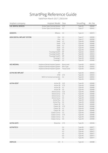
Renewal PartsPage 4VacClad-W Type VCP-W5 and 15 kV, 36-inch WideSwitchgear ComponentsEffective: July 2002Breaker Pan AssemblySpace Heater 1Levering-In AssemblyStationary Secondary ContactsTOC Switch AssemblySecondary Slide AssemblyMOC Switch AssemblyKirk Key Interlock Assembly 2Stationary Rail Assembly (L. H.)Padlock Interlock Assembly 3Stationary Rail Assembly (R.H.)Pan Assembly 4Breaker Pan Assembly PartsTable 4. Breaker Pan Assembly PartsDescriptionStyleNumberPan Assembly (1200/2000A)Pan Assembly (3000A)6529C21G03 46529C21G04 4Levering-in Assembly (1200/2000A)Levering-in Assembly (3000A)692C662G02692C662G03TOC Switch AssemblyTOC Switch Only (10 contacts)6510C49G03 5698B822H01Kirk Key Interlock Assembly6510C48G03 2MOC Switch Assembly, 5A/4B, 1 Sw. Connect & TestMOC Switch Assembly, 5A/4B, 1 Sw. Connect OnlyMOC Switch Assembly, 10A/8B, 2 Sw. Connect & TestMOC Switch Assembly, 10A/8B, 2 Sw. Connect Only6510C50G02 56510C50G03 56510C50G04 56510C50G05 5MOC Switch Assembly, 15A/12B, 3 Sw. Connect & TestMOC Switch Assembly, 15A/12B, 3 Sw. Connect OnlyMOC Switch Only6510C50G06 56510C50G07 5698B822H01Stationary Rail Assembly, Left HandStationary Rail Assembly, Right Hand6510C01G026510C02G02Padlock Interlock AssemblyStationary Secondary Contacts and Wiring HarnessSecondary Contact Slide Assembly691C540G01 36510C61G02691C573G0112345When a Pan Assembly space heater is required, this is where it is mounted. Refer to Space HeaterTable 35 on Page 17 for ratings and style numbers.Designed for Kirk Key type F (one or two locks) interlock with zero bolt projection.Key lock not included.Padlock not included.Includes the Left Hand and Right Hand Stationary Rail Assembly, the appropriate Levering-inAssembly and the Stationary Secondary Contacts.Includes mounting bracket, switch and wiring harness.Note: See Breaker Pan Assembly Parts photos on Page 5.For more information visit: www.cutler-hammer.eaton.comRP02204001E
VacClad-W Type VCP-W5 and 15 kV, 36-inch WideSwitchgear ComponentsRenewal PartsEffective: July 2002Page 5Breaker Pan Assembly PartsMountingBracketsTOC SwitchWiring HarnessPan Assembly 1Levering-in AssemblyTOC Switch Assembly 2MountingBracketMOCSwitch1234WiringHarnessKirk Key Interlock Assembly 3MOC Switch Assembly 2Stationary Rail AssemblyPadlock Interlock Assembly 4Stationary Secondary Contacts andWiring HarnessSecondary Contact Slide AssemblyIncludes the Left Hand and Right Hand Stationary Rail Assembly, the appropriate Levering-in Assembly and the Stationary Secondary Contacts.Includes mounting bracket, switch and wiring harness.Designed for Kirk Key type F (one or two locks) interlock with zero bolt projection. Key lock not included.Padlock not included.RP02204001EFor more information visit: www.cutler-hammer.eaton.com
Renewal PartsPage 6Effective: July 2002VacClad-W Type VCP-W5 and 15 kV, 36-inch WideSwitchgear ComponentsBreaker Cubicle ComponentsTable 5. Stab Molding Assembly 1Stab Molding Assembly 1DescriptionApplicationStyleNumber1200A Porcelain2000A Porcelain3000A PorcelainBus SideBus SideBus Side6437C76G016437C76G036355C65G021200A Glass Polyester2000A Glass Polyester3000A Glass PolyesterBus SideBus SideBus Side6437C76G056437C76G076355C65G031200A Porcelain2000A Porcelain3000A PorcelainLine SideLine SideLine Side6437C76G026437C76G046355C65G021200A Glass Polyester2000A Glass Polyester3000A Glass PolyesterLine SideLine SideLine Side6437C76G066437C76G086355C65G031Each style provides for three poles of a breaker. Bus Side is defined as the bottom poles of abreaker mounted in the top location, and the top poles of a breaker mounted in the bottom location. Line Side is defined as the top poles of a breaker mounted in the top location, and the bottom poles of a breaker mounted in the bottom location. Glass polyester insulation is standard.Table 6. Mounting Kits and AssembliesCT Barrier Mounting KitDescriptionStyleNumberCT Barrier Mounting KitShutter Assembly3A38291G016529C22G01Shutter AssemblyFor more information visit: www.cutler-hammer.eaton.comRP02204001E
VacClad-W Type VCP-W5 and 15 kV, 36-inch WideSwitchgear ComponentsBreaker Cubicle ComponentsPage 7DescriptionStyleNumberWith No CTsWith One Type ABB SCV or ITI 780/PoleWith Two Type ABB SCV or ITI 780/PoleWith One Type ABB SCV-D or ITI 785/PoleWith One Type ABB BYZ or ITI 1433A38292G01 13A38292G02 13A38292G03 13A38292G04 13A38292G05Used for mounting to Stab Molding Assembly (see Page 6).Table 8. ABB Current Transformers 2RatioAccuracyClassStyleNumberType SCV Narrow Profile Standard AccuracyCT Mounting Hardware KitTable 10. ITI Current Transformers 3RatioAccuracyClassStyleNumberNarrow Profile Standard 3H043A40263H053A40263H06500/5600/5600/5 600/5600/5 H113A40263H121200/5 53C88H131200/5 40263H152000/5 53C88H152000/5 40263H183000/5 (MR)4000/54000/5 /5 (MR)4000/54000/5 (MR)C200C200C2003A40263H193A40263H203A40263H21Type SCV-D Thick Profile High AccuracyThick Profile High 00C2003A40264H073A40264H083A40264H09600/5600/5 1600/5 0264H121000/51200/51200/5 /51200/5 151500/52000/52000/5 /52000/5 182500/53000/53000/5 /53000/5 (MR)C400C4003A40264H193A40264H204000/54000/5 003A40264H213A40264H22Zero Sequence CT2ITI Zero Sequence CTEach pole can accommodate up to two standard accuracy CTs or one high accuracy CT.Note: (MR) Multi-Ratio Transformers.Table 9. Type ABB BYZ Zero Sequence CTRP02204001EEffective: July 2002Table 7. Current Transformer Mounting Hardware Kit1Current Transformers Mounted onStab Molding Assembly 2Renewal 353C97H016353C97H02For more information visit: H013A40265H02Each pole can accommodate up to two standard accuracy CTs or one high accuracy CT.Note: (MR) Multi-Ratio Transformers.
Renewal PartsPage 8Effective: July 2002VacClad-W Type VCP-W5 and 15 kV, 36-inch WideSwitchgear ComponentsAuxiliary Drawer — ABB TransformersVoltage Transformer Basic Chassis 1Line-to-Ground Voltage TransformerLine-to-Line Voltage TransformerPolyesterShownSecondary Pull Fuse Assembly 2Primary FusesTable 11. Voltage TransformersSystemVoltsABBTypePrimary Contact Insulator AssemblyTable 12. Voltage Transformer Primary FusesRatioStyleNumberFuseRatingLine-to-Ground Transformers — One Primary Fuse per 187525A65G19Line-to-Line Transformers — Two Primary Fuses per TransformerFuse Size in InchesLengthDiameterStyleNumber5.5 kV – 1.0A5.5 kV – 1.0A9.509.501.631.635981C05G055981C05G058.3 kV – 1.0A15.5 kV – 1.0A9.5012.881.631.635981C06G055981C07G05Table 13. Auxiliary Drawer Chassis and AssembliesDescriptionStyleNumberVoltage Transformer Basic Chassis 11C14523G03Secondary Pull Fuse Assembly 22-Pole3-Pole3A38297G013A38297G02Primary Contact Insulator e Voltage Transformer Chassis does not include the voltagetransformer, the primary fuses and the secondary pull fuse assembly.Includes the mounting box, secondary pull fuse with 6A fuses andwiring harness.For more information visit: www.cutler-hammer.eaton.comRP02204001E
Renewal PartsVacClad-W Type VCP-W5 and 15 kV, 36-inch WideSwitchgear ComponentsAuxiliary Drawer — ITI TransformersPage 9Table 14. VCP-W Line-to-Line Transformers Mounting Plate Assembly —Including PTs and Stabs — ITI Voltage Transformers(Two Primary Fuses per Transformer)SystemLine-to-Line VoltsITI Line-to-Line PT Plate AssembliesEffective: July 01C17639G031C17639G041C17639G051C17639G06Table 15. Line-to-Line Transformers (Two Primary Fuses per Transformer)Includes PT Only — Fuses, Fuse Clips, and the Mounting Plate AssemblyAre Not IncludedSystemLine-to-Line 203A40266H053A40266H063A40266H073A40266H08ITI Line-to-Ground PT Plate AssembliesTable 16. VCP-W Line-to-Ground Transformers Mounting PlateAssembly — Including PTs and Stabs — ITI Voltage Transformers(One Primary Fuse per Transformer)SystemLine-to-Line 011C17613G021C17613G04Contact 00/1201C17654G051C17614G05Table 17. Line-to-Ground Transformers (One Primary Fuse per Transformer)Includes PT Only — Fuses, Fuse Clips, and the Mounting Plate AssemblyAre Not IncludedSystemLine-to-Line 013A40267H023A40267H03Contact 00/1203A40267H133A40267H14Note: Please contact the factory for part numbers and pricing forreplacement parts included in the ITI mounting plate assemblies.RP02204001EFor more information visit: www.cutler-hammer.eaton.com
Renewal PartsPage 10VacClad-W Type VCP-W5 and 15 kV, 36-inch WideSwitchgear ComponentsEffective: July 2002Auxiliary DrawerControl Power Transformer Basic Chassis 1Control Power TransformerControl Power TransformerSecondary Breaker (2-Pole)Table 21. Control Power Transformers 3RatedPrimaryVoltagekVARatingRecommendedFuse 15510155.5 kV – 5.0E5.5 kV – 10.0E5.5 kV – 10.0E5.5 kV – 3.0E5.5 kV – 5.0E5.5 kV – 5.0E8.3 kV – 3.0E8.3 kV – 3.0E8.3 kV – 5.0E8.3 kV – 3.0E8.3 kV – 3.0E8.3 kV – 3.0E15.5 kV – 3.0E15.5 kV – 3.0E15.5 kV – 3.0E15.5 kV – 3.0E15.5 kV – 1.5E15.5 kV – 3.0E15.5 kV – 1.0E15.5 kV – 1.5E15.5 kV – 3.0E15.5 kV – 1.0E15.5 kV – 1.0E15.5 kV – 10155101551015510155101551015510155.5 kV – 5.0E5.5 kV – 10.0E5.5 kV – 10.0E5.5 kV – 3.0E5.5 kV – 5.0E5.5 kV – 5.0E8.3 kV – 3.0E8.3 kV – 3.0E8.3 kV – 5.0E8.3 kV – 3.0E8.3 kV – 3.0E8.3 kV – 3.0E15.5 kV – 3.0E15.5 kV – 3.0E15.5 kV – 3.0E15.5 kV – 3.0E15.5 kV – 1.5E15.5 kV – 3.0E15.5 kV – 1.0E15.5 kV – 1.5E15.5 kV – 3.0E15.5 kV – 1.0E15.5 kV – 1.0E15.5 kV – e Link Extension Kit 2Table 18. Control Power Transformers Primary FusesRatingFuse Size in InchesLengthDiameterStyleNumber5.5 kV – 3.0E5.5 kV – 5.0E5.5 kV – 77C453G048.3 kV – 3.0E8.3 kV – 5.0E8.3 kV – 02677C453G0515.5 kV – 1.0E15.5 kV – 1.5E11.5011.501.621.625981C07G05677C452G1015.5 kV – 3.0E15.5 kV – Table 19. Auxiliary Drawer Chassis and Extension KitsDescriptionStyleNumberControl Power Transformer Basic Chassis 1Fuse Link Extension Kit 26511C30G048276A95G0112The Control Power Transformer Chassis does not include the controlpower transformer, the primary fuses or the secondary breaker.Required for Control Power Transformer primary fuses that are 8.12and 11.50 inches in length.Table 20. Control Power Transformers Secondary Breaker (2-Pole)CPT(kVA 132001380013800138003All Control Power Transformers have 1 7.5% Primary Tap and a120/240 volt secondary.For more information visit: www.cutler-hammer.eaton.comRP02204001E
Renewal PartsVacClad-W Type VCP-W5 and 15 kV, 36-inch WideSwitchgear ComponentsEffective: July 2002Page 11Auxiliary DrawerTable 22. Auxiliary Drawer PartsDescriptionStyleNumberDrawout Fuse Basic Chassis 16511C24G04Fuse Link Extension Kit 23A38293G01Fuse Barrier 3Used with 11 or 14-inch fusesUsed with 16-inch fuses8244A04G018244A04G02Fuse Stab Top Contact8276A25H01Fuse Stab Bottom Contact8276A27H021Drawout Fuse Basic Chassis 123Basic chassis does not include the high voltage fuse clips, fuses or the required key interlockingwith the secondary load breaker. The chassis is designed for a Kirk Key type F interlock with zeroprojection. The chassis will accommodate the fuses listed below and the Voltage Transformerfuses listed on Page 8 and the Control Power Transformer fuses listed on Page 10.Required for drawout fuses that are 14 and 16 inches in length.Required one per fuse.Table 23. Primary Fuses 4Fuse Link Extension Kit 2Fuse Barrier 3RatingLengthDiameterStyleNumber5.5 kV – 15E5.5 kV – 20E5.5 kV – 678C240G068.3 kV – 15E8.3 kV – 20E8.3 kV – 678C240G0915.5 kV – 10E16.121.62677C453G064Fuse Size in InchesSee Primary Fuses photo on Page 8.Fuse Stab Top ContactFuse Stab Bottom ContactRP02204001EFor more information visit: www.cutler-hammer.eaton.com
Renewal PartsPage 12Effective: July 2002VacClad-W Type VCP-W5 and 15 kV, 36-inch WideSwitchgear ComponentsAuxiliary Drawer ComponentsTable 24. Auxiliary Drawer ComponentsDescriptionStyleNumberFuse Clip Mounting KitDrawout Fuse Chassis (1.62 Fuse Diameter)Drawout Fuse Chassis (2.00 Fuse Diameter)CPT Chassis (1.62 Fuse Diameter)3A38296G013A38296G023A38296G03Bearing Wheel AssemblyChassis HandleMale Secondary Contact Assembly3A38294G018341A34H016511C08G02Fuse Clip Mounting KitBearing Wheel AssemblyChassis HandleMale Secondary Contact AssemblyFor more information visit: www.cutler-hammer.eaton.comRP02204001E
VacClad-W Type VCP-W5 and 15 kV, 36-inch WideSwitchgear ComponentsRenewal PartsEffective: July 2002Page 13Auxiliary Cubicle ComponentsFinger AssemblyTable 25. Auxiliary Cubicle ComponentsDescriptionSpacer and PlateStyleNumberStandoff Insulator PartsInsulatorStandoff Insulator6-inch Glass Polyester Insulator6-inch Porcelain Insulator5227B11H068289A17H01SpacerPlateFinger (Two Required per Assembly)8080A24H018080A59H013755A05H01Shutter AssemblyVoltage TransformersControl Power TransformersDrawout Fuses6511C10G026511C10G026511C10G03Ground Straps 1For 15 kV Voltage TransformersFor 5 kV Voltage Transformers8346A74G01 18346A74G05 1For 5 and 15 kV Control Power TransformersFor 5 and 15 kV Drawout Fuses8346A74G02 18346A74G03 1AssemblyShutter Assembly(CPT Assembly Shown)Female Secondary Contact Assembly6511C09G02Left Hand Stationary Rail AssemblyRight Hand Stationary Rail Assembly6511C25G016511C26G011Required one per fuse.Ground Strap 1Female Secondary Contact AssemblyStationary Rail AssemblyRP02204001EFor more information visit: www.cutler-hammer.eaton.com
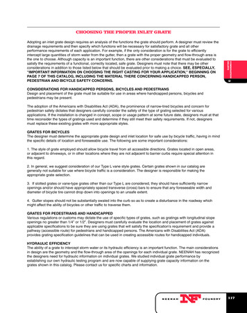
Renewal PartsPage 14VacClad-W Type VCP-W5 and 15 kV, 36-inch WideSwitchgear ComponentsEffective: July 2002Bus CompartmentFor 1200A and2000A BusFor 3000A BusHardwareInsulator CapInsulator Spacer /Hardware KitBus Riser(shown forreference only)Bus Support SnubbersBus SupportInsulatorBus Riser Support KitMain BusTable 26. Bus Riser Support Kit(Includes Hardware and Hardware Insulator Cap)Requiredper UnitSize inInchesAmpereRatingStyleNumber11.250 x 6.00.250 x 4.00120012006436C66G026436C66G0211.500 x 6.00.375 x 6.00200030006436C66G036436C66G04Table 27. Bus Riser Support PartsDescriptionStyleNumber3.5-inch Glass Polyester Insulator3.5-inch Porcelain Insulator8289A17H138289A17H03Insulator Spacer/Hardware KitHardware Insulator Cap8346A75G013A37452H01Splice PlateTable 30. Main Bus with Required Drilling and Fluidized Insulation1200A One .250 x 6.00 or One .250 x 4.002000A One .500 x 6.003000A Two .375 x 6.00(All Bus Bars are 34 inches in Length)Requiredper UnitAmpereRatingThicknessin InchesType ofPlatingStyleNumber33361200120020003000.250 x 6.00.250 x 4.00.500 x 6.00.375 x 044H0333361200120020003000.250 x 6.00.250 x 4.00,500 x 6.00.375 x 9B044H07509B044H08Table 31. Splice Plates (Silver-Plated Copper)DescriptionTable 28. Bus SupportDescriptionStyleNumberGlass Polyester 5 and 15 kVPorcelain 15 kV6355C58H016355C77G01Table 29. Bus Support SnubbersStyleNumber6-inch Bus.250-inch without Inserts.250-inch with Inserts8080A40H018080A47G01.250-inch Spacer.375-inch Spacer8080A38H018080A39H014-inch BusDescriptionStyleNumberFor .250-inch x 6-inch bus — 1200AFor .250-inch x 4-inch bus — 1200AFor .500-inch x 6-inch bus — 2000AFor Two .375-inch x 6-inch bus — inch without Inserts.250-inch with Inserts.250-inch SpacerFor more information visit: 6096H10RP02204001E
VacClad-W Type VCP-W5 and 15 kV, 36-inch WideSwitchgear ComponentsRenewal PartsEffective: July 2002Page 15Bus CompartmentTable 32. BootsDescriptionStyleNumberMain Bus or Butt Joint Boot1200/2000A, 1/2/3 Way, 6-inch Bus1200/2000A, 4 Way, 6-inch Bus3000A, 6-inch Bus1200A, 4 Way, 4-inch Bus1C14751H011C14751H021C14759H011C18509H01Breaker Stud Boot Bus Side and ClosureMain Bus or Butt Joint Boot1200A Stud1200A Closure6359C17H01 16359C90H01 12000A Stud2000A Closure6359C66H01 16359C97H01 13000A Stud3000A Closure6359C99H01 16359C98H01 1Breaker Stud Boot Line Side and ClosureClosureBreaker Stud Boot Bus Side and Closure1200A Stud1200A Closure6531C80H01 16531C81H01 12000A Stud2000A Closure6531C82H01 16531C83H01 13000A Stud3000A Closure6359C99H01 16359C98H01 11Three sets required per breaker.Table 33. BootsDescriptionStyleNumberCopper to Bus Run BootClosureBreaker Stud Boot Line Side and Closure1200A (RH)1200A (LH)1200A (CTR)6438C25H016438C26H016438C27H012000A (RH)2000A (LH)2000A (CTR)6438C32H016438C33H016438C34H013000A (RH)3000A (LH)3000A (CTR)6438C28H016438C29H016438C30H0190º Turn Lap Joint Boot1200A2000ACopper to Bus Run Boot6364C01H016364C02H01User Cable Termination Boot1200A Single Row of Terminals — Solid Copper Riser and Terminal Adapter1200A Double Row of Terminals — Solid Copper Riser and Terminal Adapter2000A Single Row of Terminals — Solid Copper Riser and Terminal Adapter2000A Double Row of Terminals — Solid Copper Riser and Terminal 0A 1 and 2 Cables Per Phase-Bolted Terminal Adapter1200A 3 Cables Per Phase-Bolted Terminal Adapter2000A 1 and 2 Cables Per Phase-Bolted Terminal Adapter2000A 3 Cables Per Phase-Bolted Terminal e: Please note that no cable termination boots for 1200A .25-inch x 4-inch bus areavailable at this time.90º Turn Lap Joint BootUser Cable Termination BootRP02204001EFor more information visit: www.cutler-hammer.eaton.com
Renewal PartsPage 16Effective: July 2002VacClad-W Type VCP-W5 and 15 kV, 36-inch WideSwitchgear ComponentsAccessories and Miscellaneous PartsMaintenance ToolLevering Crank with ClutchBreaker Lifting YokeRail ExtensionsRail ClampsBreaker Ramp AssemblyDockable DollyPortable Lifting CraneTable 34. Accessories and Miscellaneous PartsDescriptionStyleNumberVCP-W Maintenance ToolArc Resistant Maintenance Tool8064A02G013A71173G01Standard Levering Crank with ClutchThrough Door Levering Crank with Clutch701B601G01701B601G13Breaker Lifting YokePortable Lifting Crane691C607G013A40094H11Right Hand Rail ExtensionLeft Hand Rail Extension7813C41G017813C41G02Rail ClampsBreaker Ramp Assembly6511C83G011C14163G12Indoor Dockable DollyOutdoor Aisleless Dockable Dolly6510C71G016510C71G03For more information visit: www.cutler-hammer.eaton.comRP02204001E
VacClad-W Type VCP-W5 and 15 kV, 36-inch WideSwitchgear ComponentsRenewal PartsEffective: July 2002Page 17Accessories and Miscellaneous PartsTable 35. Space 3614A50H02125250951003614A50H043614A50H05Table 36. Accessories and Miscellaneous PartsDescriptionSpace HeaterStyleNumberTest Jumper 1Used with internal power from breaker6526C23G01Test Cabinet 2Any DC Close and Trip Combination — StandardAny AC/DC Close and Any DC Trip Separate — Standard8346A28G018346A28G02120, 240V AC Close, Capacitor TripAny DC Close, Trip Combination Separate Motor8346A28G038346A28G04Capacitor Trip120V240V12Used with internal power from breaker.Used with a separate power source.Test Jumper 1Test Cabinet 2Capacitor TripRP02204001EFor more information visit: www.cutler-hammer.eaton.comCTD-2CTD-4-240
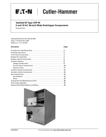
Renewal PartsPage 18Effective: July 2002VacClad-W Type VCP-W5 and 15 kV, 36-inch WideSwitchgear ComponentsTechnology UpgradesNew Replacement Front PanelsWith a new replacement front panel, itis now possible to have state-of-the-artsolid-state metering and relaying, withthe capability to communicate to aPowerNet system. This upgrade alsoeliminates the need to cut and patchexisting panels or replace thecomplete line-up.Medium voltage switchgear that wasmanufactured between 1963 and thepresent can now be upgraded withsolid-state meters and relays to monitorand protect your distribution system.This replacement front panel upgradecapability applies to:DHP Switchgear 1963 – 1984VCP Switchgear 1981 – 1986 VCP-W Switchgear 1986 – Present Older VCP-W Front Panelwith Analog Metering andInduction Disk Type RelaysNew front panels come with devicesmounte
Breaker Cubicle Components Stab Molding Assembly 1 CT Barrier Mounting Kit Shutter Assembly Table 5.ÊStab Molding Assembly 1 1 Each style provides for three poles of a breaker. Bus Side is defined as the bottom poles of a breaker mounted in the top location, and the top poles of a breaker mounted in the bottom loca-tion. Line Side