Transcription
Pure Storage Reference Architecture withCitrix XenDesktop 5.6
OverviewThis document describes a reference architecture for deploying virtual desktops on the Pure StorageFlashArray using Citrix XenDesktop 5.6, Citrix Provisioning Services 6.1, vSphere 5.1 Hypervisor andMicrosoft Windows 7. Pure Storage has validated the reference architecture with Login VSI Pro 3.7medium workload in its lab – this document presents performance and scalability testing results andoffers implementation guidance.GoalsandObjectivesThe goal of this document is to showcase the ease of deploying a large number of virtual desktops onthe Pure Storage FlashArray. We will demonstrate the scalability of Citrix XenDesktop based Windows7 desktops on the FlashArray by deploying 500 virtual desktops using Citrix Provisioning Services(PVS) and running the Login VSI Pro workload to simulate real user interaction and experience in a VDIworkload. In addition, we highlight the benefits of the Pure Storage FlashArray including inline datareduction and low latency and show how all-flash storage can dramatically improve both the end-userand administrative experience of VDI compared to traditional disk-based storage.AudienceThe target audience for this document includes storage and virtualization administrators, consultingdata center architects, field engineers, and desktop specialists who want to implement CitrixXenDesktop based virtual desktops on the FlashArray. A working knowledge of VMware vSphere,Citrix XenDesktop, server, storage, network and data center design is assumed but is not aprerequisite to read this document. Pure Storage 2013 2
SummaryofFindings We deployed 500Citrix XenDesktopbasedWindows7desktops and ran a realistic loadgenerator with Login VSI Pro 3.7 that simulated 500 users performing common computingtasks, resulting in a best- ‐in- ‐classscoreof720. This score means the majority of the applicationshad a response time of 720 milliseconds or less, well within the VSImax of 4000 milliseconds. Throughout the testing the FlashArray delivered and maintained latency under 1 millisecond,demonstrating the FlashArray’s consistent latency and abilitytodeliverthebestall- ‐flashVDIend- ‐userexperienceatalltimes. The FlashArray delivers a better desktop experience for end-usersthan dedicated laptops with SSDs, and doesn’t risk the end-user experience by relying oncaching as hybrid flash/disk arrays do. In total throughout the testing we deployed more than 1,000 desktops (each of 5 GB writecache), together only consuming less than 1 TB of physical storage on the FlashArray. Thismassive data reduction (10-to-1) is the result of the high-performance inline data reduction(deduplication and compression) delivered by the FlashArray, which enablesustohostamassiveamountofdesktops. Based on the current testing, the 11 TB FlashArray, FA-320, has the ability to deliver best- ‐in- ‐classVDIperformanceatacostof 100/desktop. Since the FlashArray was significantly under-utilizedthroughout the testing on both a capacity and performance basis, the array could havesupported 1,000s more desktops, or a smaller array could have been used, either of whichwould have reduced the /desktop cost even further. Throughout the testing we performed common VDI administrator operations and found adrastic reduction in time for patching desktops, adding new desktop groups, (re)bootingdesktops, logon/logoff storms, and other day-to-day virtual desktop operations. Takentogether these sforVDIadministratorsthroughout the VDI day. The power footprint for the tested FA-320 FlashArray was 9 Amps (110V) which is a fraction ofany mechanical disk storage array available in the marketplace. This configuration consumedeight rack units (8 RU) in data center space. This reference architecture can be treated as a 500 desktop building block. Customers canadd more Provisioning Services (PVS) to the PVS farm, and scale their Desktop Controller(DDC), hosting server and infrastructure components to scale the architecture out to 1,000s ofdesktops. Based on the results, asingleFA- ‐320cansupportupto5,000desktops with any mix ofdesktop user types. Pure Storage 2013 3
IntroductionThe IT industry has been abuzz over the past several years promoting the idea of VDI: virtualizing andcentralizing desktops to enable IT to deliver a more secure, manageable, less costly, and ultimatelymore mature end-user computing model. While the dream of pervasive deployment of virtual desktopinfrastructure has been discussed and tried for literally decades, the recent explosion of x86virtualization, and the availability of commodity scalable server architectures with increasingly largeamounts of CPU power and centralized memory have made the promise of VDI much closer to reality.In fact, sophisticated IT departments are finding that with the right investments in infrastructure, VDIcan deliver a client computing model that is both better for the end-user (a truly mobile, multi-devicecomputing experience with better performance than dedicated devices) and better for the IT staff(centralized management, consistent security and policy enforcement, resiliency through deviceindependence, and enablement of “bring your own device” BYOD models).So if VDI comes with so many potential advantages, why has adoption of VDI been so slow? Thereality is that the path to achieving the VDI promise land is a difficult one, and many organizations haveabandoned their VDI initiatives outright or in partial stages of deployment. There are many reasons,but most failed deployments boil-down to three key issues: Too expensive: VDI is often positioned as a technology to reduce desktop cost, but in realitymost find that they are unable to achieve the promised ROI due to infrastructure costs. Inparticular, server, networking, and storage devices are often dramatically more expensive thandedicated desktops/laptops. Poor end-user experience: if VDI isn’t implemented properly, the end result is slow orunavailable desktops that can lead to user frustration and lost productivity. Too difficult to manage: VDI shifts the desktop administration burden from the end-users to ITstaff. While this affords many security and administrative benefits, it also means more work foroften burdened IT staff, especially if the VDI environment itself isn’t architected correctly.More often than not, one of the chief contributors to all three of these failure modes is storage.Traditional disk-based storage is optimized for high-capacity, modest performance, and read-heavyworkloads – the exact opposite of VDI which is write-heavy, very high performance, and low-capacity.The result is that as performance lags, spindle after spindle of legacy disk storage has to be thrown atVDI, causing a spike in infrastructure costs and a spike in management complexity.In this reference architecture for virtual desktops we’re going to explore how a new, 100%-flash basedapproach to VDI can help overcome the key VDI failure traps, and help deliver a VDI solution that bothend-users and IT administrators will love. We’ll start with a high level overview of the Pure StorageFlashArray, then we’ll go over the test infrastructure components put together for this work and diveinto the details of each component. Finally, we’ll discuss the results of the Login VSI Pro loadgenerator and the operational benefits of using the Pure Storage FlashArray for virtual desktopdeployment. Pure Storage 2013 4
ThePureStorageAll- ‐FlashSolutionforVDIIntroducingPureStoragePure Storage was founded with a simple goal in mind: that 100% flash storage should be madeaffordable, so that the vast majority of enterprise applications can take advantage of the potentialadvances that flash memory affords. As such we designed our core product, the Pure StorageFlashArray, from the ground-up for the unique characteristics of flash memory.The FlashArray’s entire architecture was designed to reduce the cost of 100% flash storage. Itcombines the power of consumer-grade MLC flash memory with inline data reduction technologies(deduplication, compression, thin provisioning) to drive the cost of 100% flash storage to be inline orunder the cost of traditional enterprise disk storage. Data reduction technologies are particularlyeffective in VDI environments, typically providing 5-to-1 reduction for stateless desktops and 10-to-1reduction for stateful desktops.High-PerformanceInline Data Reductionalways deduped, compressed,thin and encryptedResiliency & Scalehigh availabilitysnapshotsRAID-3D online expansion100% MLC FlashSimplicityIt’s important to note that unlike some flash appliances, the FlashArray was designed with enterpriseclass scale and resiliency in mind. That means a true active/active controller architecture, onlinecapacity expansion, and online non-disruptive code upgrades. The FlashArray also employs a uniqueform of RAID protection, called RAID-3D , which is designed to protect against the three failure modesof flash: device failure, bit errors, and performance variability.Last but not least, the FlashArray is the simplest enterprise storage that you’ll ever use. We’vedesigned from the start to remove the layers of complexity of LUN, storage virtualization, RAID, andcaching management common in traditional arrays, and have integrated management directly intoVMware vSphere’s Web Client, making management of a VDI environment seamless. Pure Storage 2013 5
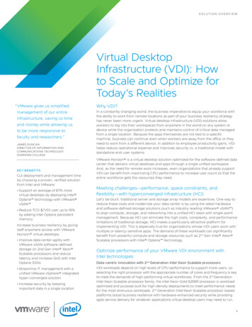
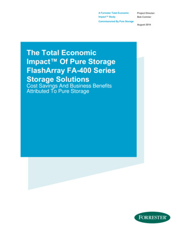
ReferenceArchitectureDesignPrinciplesThe guiding principles for implementing this reference architecture are: Create a scalable building block that can be easily replicated at any customer site using acustomer’s chosen server and networking hardware. Implement every infrastructure component in a VM. This ensures easy scale-out ofinfrastructure components when you go from 500 to 5,000 virtual desktops. Create a design that is resilient, even in the face of failure of any component. For example, weinclude best practices to enforce multiple paths to storage, multiple NICs for connectivity, andhigh availability (HA) clustering including dynamic resource scheduling (DRS) on vSphere. Take advantage of inline data reduction and low latency of the Pure Storage FlashArray topush the envelope on desktops-per-server density. Avoid tweaks to make the results look better than a normal out-of-box environment.SolutionOverviewFigure 1 shows a topological view of the test environment for our reference architecture. The CitrixXenDesktop 5.6 infrastructure components were placed on a dedicated host. We deployed 1,000 PVSbased desktops but due to the high CPU requirement of Login VSI Pro 3. 7 medium workload, we wereable to run the load on 500 desktops. The infrastructure, virtual machines and desktops were allhosted on a single 11 TB FlashArray FA-320 (although the workload would have easily fit on thesmallest 2.75TB FA-320 or FA-310 as well). VMware vSphere and Citrix XenDesktop best practiceswere used in addition to the requirements as mandated by the Login VSI document [See reference 4].The tested configuration included: One 11 TB Pure Storage FlashArray (FA-320) in HA configuration, including two controllers andtwo disk shelves:— One 40 TB volumes was carved out of the Pure FlashArray to host 1,000 desktops— A separate 600 GB volume was used to hold all the infrastructure component Eight Intel Xeon x5690 based commodity servers with 192 GB of memory running ESXi 5.1were used to host the desktops Three dedicated Intel Xeon x5690 based commodity servers were used to host all of theinfrastructure virtual machines:— Active directory, DNS, and DHCP— Citrix Provisioning Services (PVS) 6.1 Pure Storage 2013 6
— Citrix Desktop Delivery Controller (DDC)— VMware Virtual Center Server 5.1— SQL server for both Virtual Center and PVS database— A Citrix License server VM which also hosted the Login VSI Share— Login VSI launcher each running 35 sessionsFigure 1: Test Environment overview of Citrix XenDesktop deployment with infrastructurecomponents, ESX hosts and Pure Storage FlashArray volumes. Pure Storage 2013 7
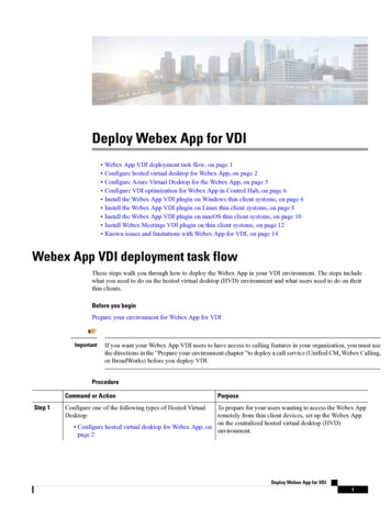
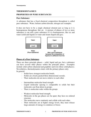
ReferenceArchitectureConfigurationThis section describes the Reference Architecture configuration in brief. Later sections have detailedhardware and software configurations.Figure 2: Detailed Reference Architecture ConfigurationFigure 2 shows a detailed topology of the reference architecture configuration. A major goal of thearchitecture is to build out a highly redundant and resilient infrastructure. Thus, we used powerfulservers with dual Fiber Channel (FC) ports connected redundantly to two SAN switches that wereconnected to redundant FC target ports on the FlashArray. The servers were hosted in a vSphere HAcluster and had redundant network connectivity with two or more Ethernet ports teamed. Themanagement ports (not shown in the diagram) were connected to a separate management switch. Pure Storage 2013 8
HardwareConfigurationPureStorageFlashArrayFA- ‐320configurationThe FlashArray FA-320 configuration has two active/active controllers and two shelves of 5.5 TB ofraw flash memory for a total of 11 TB of raw storage. Four Fiber Channel ports were connected to twoCisco MDS 9148 8Gb SAN switches in a highly redundant configuration as shown in Figure 2. Table Abelow describes the specifications of the FlashArray FA-320.ComponentDescriptionControllersTwo active/active controllers which provided highly redundant SAS connectivity(24 Gb) to two shelves and were interconnected for HA via two redundantInfiniBand connections (40 Gb).ShelvesTwo flash memory shelves with 22 SSD drives, 22 X 256 GB or a total rawcapacity of 11 TB (10.3 TB).ExternalConnectivityFour 8 Gb Fibre Channel ports or four 10 Gb Ethernet ports per controller, total ofeight ports for two controllers. As shown in figure 2, only four Fibre Channel ports(two FC ports from each controller) were used for this test.ManagementPortsTwo redundant 1 Gb Ethernet management ports per controller. Threemanagement IP addresses are required to configure the array, one for eachcontroller management port and a third one for virtual port IP address for seamlessmanagement access.PowerDual power supply rated at 450W per controller and 200W per storage shelf orapproximately 9 amps of power.SpaceThe entire FA-320 system was hosted on eight rack unit (8 RU) space (2 RU foreach controller and 2 RU for each shelf).Table A: Pure Storage FlashArray FA-320 specificationsThere was no special tweaking or tuning done on the FlashArray; we do not recommend any specialtunable variables as the system is designed to perform out of the box. Pure Storage 2013 9
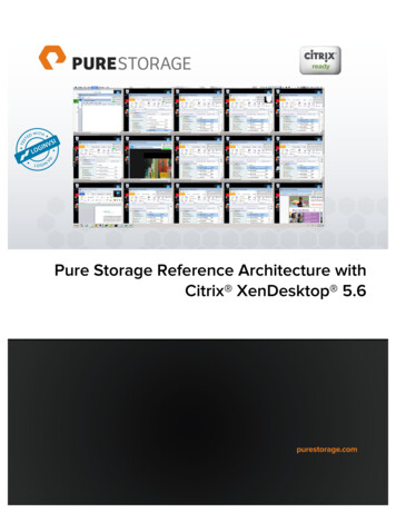
LUNConfigurationoftheFlashArrayOne 40 TB thin provisioned volume was configured to host 500 desktops. Because the FlashArraydoesn’t have any requirement for configuring RAID groups/aggregates, it was a simple two-step taskto configure Pure Storage volumes and provision to the server. The task of provisioning the volumes tovSphere cluster was further simplified by creating a host group on Pure Storage FlashArray thatprovided a one-to-one mapping with the vSphere cluster. Pure Storage provides private volumes thatcan be used for booting the server from SAN.A common question when provisioning storage is how many LUNs of what size should be created tosupport the virtual desktop deployment. Because PVS write cache for each desktops take very littlespace, we could have either put all the virtual desktops in one big LUN or spread them across severalLUNs, we chose to put all the write cache in one big datastore. The FlashArray supports the VMwareVAAI ATS primitive which gives you access to multiple VMDKs on a single LUN (Note in vSphere 5.xthe maximum size of a LUN is 64 TB). VAAI ATS eliminates serializing of VMFS locks on the LUN, whichseverely limited VM scalability in past ESX(i) versions. See Appendix A for more details on provisioningPure Storage.Now lets look at a sizing exercise, since we are advocating placing the OS image, user data, personaand application data on the same storage, we need to take into account the size of write cache whencalculating the LUN size.Consider a desktop with a 30 GB base image including applications and app data, 5 GB of user data(write cache) and we need to provision “d” desktops: We need to provision at least: base image size (5 * d) GB as the size of the LUNRegardless of the data reduction, we need to create the LUN with the correct size so that vSpheredoesn’t run out of storage capacity. Figure 3 below shows the virtual desktop deployment on PureStorage.Figure 3: OS image, applications, user data and application data hosted on Pure Storage Pure Storage 2013 10
DataReductionwithPureStorageFlashArrayStorage Capacity with 1,000 PVS based DesktopsFigure 4 below shows 1,000 Windows 7 desktops deployed on an existing FlashArray with otherworkloads running on it. The total physical capacity used was less than 1 TB for the entire 1,000desktops. Because we used PVS based desktops which stores only the differential data, we achieveda overall data reduction of 24.9-to-1.Figure 4: Data reduction of 1,000 Windows 7 desktops plus other workloads in the systemIn a real world scenario, the data reduction number is more in the order of 10-to-1 as the user datawould differ more than in our example.Unlike traditional storage arrays, we used a common LUN to store the OS image, user data, applicationdata, and persona. We don’t see any benefits in separating them on the FlashArray. We do not do datareduction on a volume basis; it is done across the entire array, which is reflected in the shared data inthe capacity bar above.The write cache LUN of 40 TB size was separately created and we saw a 9-to-1 data reduction on thewrite cache LUN as shown below in figure 5.Figure 5: Pure Storage GUI snapshot of the Write Cache Volume (PVS Cache on Server)Figure below shows Pure Storage GUI snapshot of the Pure LUN used for write cache when “cache ondevice hard disk” option was used in PVS. Note that the pagefile was automatically stored on the writecache and we saw a data reduction in excess of 7 X. Pure Storage 2013 11
ServerConfigurationEight identical Intel CPU-based commodity servers were deployed for hosting the virtual desktops. Theserver’s dual HBA ports were connected to two Cisco MDS 9148 SAN switches for upstreamconnectivity to access the Pure Storage FlashArray LUNs. The server configuration is described inTable B below.ComponentDescriptionProcessor2 X Intel Xeon X5690 @ 3.47GHz (12 Cores total, 24 Logical CPUs)Memory192 GB @ 1333 MHz (16 GB X 12)HBADual port Qlogic ISP2532-based 8 Gb Fibre Channel PCIe cardNICQuad port Intel Corp 82576 1 Gb cardBIOSIntel Virtualization Tech, Intel AES-NI, Intel VT-D features wereenabledvSphereESXi 5.1.0, Build 799733Table B: Desktop host server configurationSANConfigurationFigure 2 shows the SAN switch connectivity with two Cisco 8 Gb MDS 9148 Switch (48 ports). The keypoint to note is that there is no single point of failure in the configuration. The connectivity is highlyresilient in terms of host initiator port or HBA failure, SAN switch failure, a controller port failure, oreven array controller failure. The zoning on the Cisco MDS follows best practices i.e a single initiatorand single target zoning. Check Appendix B for a sample Cisco MDS zoning. All eight ESXi host dualHBA port World Wide Names (pWWN) were zoned to see the four Pure Storage FlashArray target portWorld Wide Names. The target ports were picked such that, on a given controller, we had one portfrom each target Qlogic adapter connected to one switch, the other Qlogic adapter port wasconnected to a second switch (See Figure 2 for the wiring details). This resulted in ESXi 5.1 hosts tosee 8 distinct paths to the Pure Storage FlashArray LUNs (Figure 6 shows vCenter datastore details).Notice the hardware acceleration support and path selection policy set to Round Robin. Pure Storage 2013 12
Figure 6: VMware VMFS datastore detailsNetworkConfigurationFigure 7 below illustrates the network design used for the desktop deployment. A virtual machine wassetup to run AD/DNS and DHCP services and we used a private domain. As large numbers of desktopswere to be deployed, we wanted to setup our own private VLAN (VLAN 131) for desktops to hand outIP addresses to virtual desktops that were spun up. A separate VLAN (VLAN 124) was used formanagement network including the ESXi hosts on a single Cisco 3750 1Gb Ethernet switch (48 ports).Figure 7: Logical view of the reference architecture showing network configuration Pure Storage 2013 13
ESXConfigurationandTuningESXi 5.1.0, build 799733 was installed on eight identical servers and a separate infrastructuremanagement server. This section talks about the storage, network, and general system configurationfollowed by specific tuning that was done to get the best performance. We started out with little or notuning and have narrowed down to a small set of ESXi tuning configurations. Due to the large numberof VMs and hosts VMware Management Assistant and vSphere powershell were used extensively andhelped us get administrative tasks done Sphere5.1The FlashArray is a VAAI-compliant, ALUA-based active/active array and doesn’t require a specialvSphere plugin to make the array work. The default storage array type plugin (SATP),VMW SATP ALUA, is automatically selected. However, the default path selection policy (PSP) is“Fixed” path. The PSP should be changed to Round Robin for all the Pure Storage LUNs as all paths toFlashArray is active optimized. This can be done using vCenter, Webclient or ESXi command line (SeeAppendix C for steps using vCenter). The following ESXi command accomplished this on a per devicebasis :esxcli storage nmp device set -d naa.6006016055711d00cff95e65664ee011 --psp ”VMW PSP RR”We set all the Pure Storage LUNs to a Round Robin policy from vMA using the CLI command :for i in esxcli storage nmp device list grep PURE awk '{print 8}' sed 's/(//g' sed's/)//g' ; do esxcli storage nmp device set -d i --psp VMW PSP RR ; doneFor our tests, we set the default PSP for VMW SATP ALUA as VMW PSP RR and every Pure StorageLUN configured got the Round Robin policy. The following command accomplished that:esxcli storage nmp satp set --default-psp "VMW PSP RR" --satp "VMW SATP ALUA"Figure 8 shows a properly configured Pure Storage LUN with VMware Round Robin PSP. Pure Storage 2013 14
Figure 8: Pure Storage LUN configured with Round Robin path policyESXi5.1ConfigurationandTuningIn this section, we discuss the ESXi 5.1 cluster configuration, network configuration and ESXi tuning forthe disk subsystem.ESXi Cluster ConfigurationA datacenter and a cluster with eight hosts were configured with VMware’s High Availability clustering(HA) and Distributed Resource Scheduling (DRS) features. DRS was set to be fully automatic so that the1,000 desktops would be evenly distributed across the eight hosts. The DRS power management wasturned off and the host EVC policy was set to “Intel Westmere.” The BIOS of each host was examinedto make sure the Intel VT-d was on, AES-NI instructions were enabled. The HA configuration was setupwith VM restart priority as high and isolation policy set to “leave powered on.” Finally, the swap file wasstored along with the VM. A resource pool was created to house the desktops with default settings.Due to the one-to-one mapping of the ESX hosts in a cluster to the Pure Storage host group and hosts,all hosts saw all the LUNs except for the private volumes used by each host for boot.ESXi Network ConfigurationTwo virtual switches each containing two vmnics were used for each host. Although this design couldhave taken advantage of Distributed vSwitch (DVS), we went with Standard vSwitch. The redundantNICs were teamed in active/active mode and VLAN configurations were done on the upstream Cisco3750 1 GE switch. The switch provided an internal private network and had a DNS helper whichredirected to the infrastructure DNS and DHCP. The virtual switch configuration and properties areshown in Figure 9 and Figure 10 respectively. Pure Storage 2013 15
Figure 9: VMware virtual switch configurationThe default 128 ports on a virtual switch were changed to 248, as there was a potential to put moredesktops on a single host (host reboot is mandated for this change). The MTU was left at 1500.Figure 10: Virtual switch properties showing 248 portsvSphere System Level TuningIn order to get the best performance out of the FlashArray some of the default disk parameters invSphere had to be changed, because the default values are applicable to spindle based arrays thatare commonly deployed in the data center. The two disk parameters that were changed to a highervalue for this work are Disk.SchedNumReqOutstanding (default value of 32) and Disk.SchedQuantam(default value of 8) to 256 and 64 respectively. The former, DSNRO, will limit the amount of I/Os thatwill be issued to the LUN. This parameter was tuned to a maximum limit so the FlashArray can servicemore I/Os. The best treatise on this topic can be found in [See reference 4]. The latter,Disk.SchedQuantum value determines the number of concurrent I/Os that can be serviced from eachworld (a world is equivalent to a process in VMkernel terms), so we set that value to its maximum valueof 64. Figure 11 below shows how to set it using a vCenter on a per host basis. Pure Storage 2013 16
Figure 11: vCenter snapshot of setting Disk tunablesThe same can be accomplished by using a vMA appliance and the command line (a script was used toconfigure these settings):esxcfg-advcfg –set 256 /Disk/SchedNumReqOutstandingesxcfg-advcfg –set 64 /Disk/SchedQuantumThe qlogic HBA max queue depth was increased to 64 from its default value on all hosts (see VMwareKB article 1267 for setting this value):# esxcfg-module qla2xxx-g ql2xmaxqdepthqla2xxx enabled 1 options 'ql2xmaxqdepth 64'There was no other tuning that was done to the vSphere server. Note, these settings are globalsettings on an ESXi server and are recommended if there are no other storage arrays connected to theserver. Pure Storage 2013 17
ManagementandInfrastructureVirtualMachinesIn order to scale the environment it is important to have robust and efficient infrastructure components.As per the design principles, we built the management and infrastructure VMs on a separatemanagement host server running ESXi 5.1.0. Why? Because as we scale this environment, we expectActive directory and DNS/DHCP will have to scale to give the best possible user experience, so we willneed dedicated host resources to support that growth.We created a master Microsoft Windows 2008 R2 template with all the updates and cloned thedifferent infrastructure VMs. The Citrix Provisioning Services (PVS) 6.1 and Citrix Desktop DeliveryController (DDC) were installed with 10G vmxnet3 network driver and was given 4 vCPU and 8 GB ofRAM. The SQL server VM hosted the Microsoft SQL Server 2008 R2 database instance of the vCenterdatabase and the Citrix PVS database. The 15 Login VSI launchers VM were Windows 7 VMs and asper Login VSI recommendations were given 2 vCPU and 8 GB of RAM. The description of each of theinfrastructure components is shown in Figure 12. Based on the experiments done, ourrecommendation is to have a single PVS and DDC VM to deploy 500 desktops. If you want to scale,one has to add more PVS and DDC VMs and build out a PVS and DDC farm.Figure 12: Infrastructure Virtual Machine component detailed descriptionThe management infrastructure host used for the infrastructure VMs was provisioned with a 600 GBLUN; the server configuration is shown in Table C below. Pure Storage 2013 18
Table C: Management infrastructure host configuration details Pure Storage 2013 19
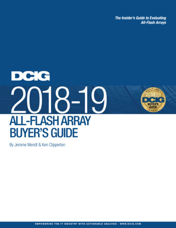
rviewCitrix XenDesktop is a desktop virtualization system that centralizes and delivers Microsoft WindowsXP, 7 or 8 virtual desktops to users anywhere. Virtual desktops are dynamically assembled on demand,providing users with pristine, yet personalized, desktops each time they log on. This ensures thatperformance never degrades, while the high speed delivery protocol provides unparalleledresponsiveness over any network. Citrix HDX delivers a high definition user experience for virtualdesktops, and offers the best performance over any network connection. The open architecture ofXenDesktop offers choice and flexibility of virtualization platform and user device. Unlike otherdesktop virtualization alternatives, XenDesktop simplifies desktop management by using a singleimage to deliver personalized desktops to users and enables administrators to manage service levelswith built-in desktop performance monitoring. Citrix FlexCast delivery technology enables you todeliver every type of virtual desktop, hosted or local, physical or virtual, each specifically tailored tomeet the performance, security and flexibility requirements of each individual user.Figure 13 below shows remote users working at their local user devices while accessing virtualdesktops provided by XenDesktop.Although the desktops are virtual, running on remote servers, the user experience is equivalent to thatof a local Windows desktop. From the user's perspective, logging on to a virtual desktop is the sameas logging on to a local desktop. Users enter their credentials once and are connected to theirdesktops.Figure 13: Citrix XenDesktop Architecture Overview Pure Storage 2013 20
ComponentsofCitrixXenDesktopDeploymentCitrix XenDesktop provides a complete virtual desktop delivery system by integrating severaldistributed components with advanced configuration tools that simplify the creation and real-timemanagement of the virtual desktop infrastructure.The core components of XenDesktop are: Des
VDI, causing a spike in infrastructure costs and a spike in management complexity. In this reference architecture for virtual desktops we're going to explore how a new, 100%-flash based approach to VDI can help overcome the key VDI failure traps, and help deliver a VDI solution that both end-users and IT administrators will love.