Transcription
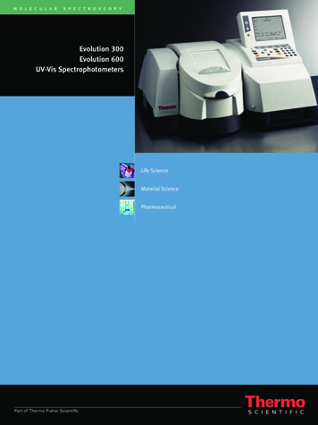
EVOLUTION IIINK JET PRINTERSINSTALLATION AND OPERATION MANUALdigital design inc.67 Sand Park RoadCedar Grove, NJ 07009(973) 857-9500http://www.evolutioninkjet.com/This manual is for use in operating and maintaining the EVOLUTION 1I Ink JetPrinter. This includes various optional features, which may not be included inyour basic model printer. For basic start-up instructions, please refer to PART 1Installation Procedures.All rights reserved. No part of this document may be reproduced, stored on aretrieval system, or transmitted in any form, or by any means electronic,mechanical, photocopying, recording or otherwise, without the prior permission ofDigital Design Inc.Digital Design Inc. has a policy of continual product improvement. The Companytherefore reserves the right to modify the information contained in this manualwithout prior notice.ALL PRINT CARTRIDGES SUPPLIED BY DIGITAL DESIGN INC.ARE FACTORY TESTED AND PROFILED TO PRODUCE ANOPTIMUM AND CONSISTANT CODE. USING OTHER THANAUTHORIZED CARTRIDGES WILL CAUSE UNDESIRABLERESULTS.EACH FLASH DATA CARD IS PROFILED EXPLICITELY FOR ITS’INTENDED PRINTER, AND IS SECURITY LOCKED PROHIBITINGUSE IN OTHER THAN THE ORIGINAL PRINTER FOR WHICH ITWAS PURCHASED. KEEP ALL UPGRADE CARDS IN A SECUREPLACE.EVOLUTION II IS A FULLY FEATURED MODEL WITH VARIABLEFIELD PROGRAMMING AND BARCODE CAPABILITIES.1EVOLUTION 1 SYSTEM MANUAL Issue 1.1 20 Dec 2006
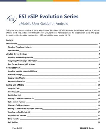
EVOLUTION CONTROLLERPRINT HEADCABLE PLUGEV2STOPPEDHD 1 - - SPEED 120EVOLUEVOLUTION CODERSGRAPHIC(WSYWIG)LCD DISPLAYNOTE:THE EVOLUTIONGRAPHIC CONTROLLERWILL CONTROL THEEVOLUTION 1(EV1)EVOLUTION 2(EV2)EVOLUTION SC(EVSC)THE UPPER LEFTCORNER OF THE DISPLAYINDICATES THE SPECIFICPRINTER CONNECTED TOTHE HAND N 1 SYSTEM MANUAL Issue 1.1 20 Dec 2006
INSTALLATION AND OPERATION MANUALPART 1: INSTALLATION PROCEDURES66INSTALLING THE EVOLUTION II PRINTING SYSTEM6MOUNTING ON PRODUCTION LINE6EVOLUTION II MOUNTING OPTIONS7After the mounting bracket is configured loosen the locking collar 7A014S and re-locate itagainst the horizontal extension bracket and tighten. This allows the user to loosen thehorizontal mounting bracket-locking knob and rotate the assembly without losing the height8adjustment.GROUNDING STRAP INSTALLATION9INPUT POWER CONNECTION AND MODIFICATION9INSTALLING THE PRINT CARTRIDGE10CONNECTING THE CONTROLLER TO THE CARRIAGE11CONFIGURING THE PRINTER12SYSTEM RESET12MULTIPLE PRINT HEADS14EVOLUTION II QUICK START15CHANGING LANGUAGE PROMPTS15ENABLING PRINT MODE15HEAD SELECT MODE15ENTERING A MESSAGE16STORING A MESSAGE17LOADING A MESSAGE18EVOLUTION II QUICK SETUP19PART 2: OPERATION PROCEDURESOVERVIEW CONTROLLER and LCDKEYPAD KEY DESCRIPTIONSTURNING ON THE PRINT STATION FOR THE FIRST TIMECHECKING SYSTEM INFORMATIONCHECKING LOADED FONTSCHANGING SYSTEM DATE AND DAY OF WEEK CODESCHANGING SYSTEM TIME AND DATE ROLL OVER TIMEPROGRAMMINGDEFINITIONSPRINT MODE AND STOPPED “COMMAND” MODEF1 MENU1 CHARACTER SPACING:2 EXT. ENCODER:3 DATE OFFSET:4 BARCODE TYPE:F2 MENU1 - DIRECTION:2 - PRINT INVERSE:3 – PRODUCT DETECT:4 - AUTO REPEAT:F3 MENU1 – PRODUCT COUNT:2 – shift code:3 – DATE FORMAT:4 – TIME FORMAT:F4 MENU1 - LANGUAGE:2 - INK SUPPLY:3EVOLUTION 1 SYSTEM MANUAL Issue 1.1 20 Dec 200611233345777999101012121212131414151618191919
3 – SET UNIT I.D.:4 – LOAD CARD:SETTING PRINT DELAY AND LINE SPEEDSETTING LINE SPEEDSETTING PRINT DELAYSETTING HEAD ALIGNMENTINPUT, EDIT OR DELETE MESSAGESVARIABLE FIELD FORMAT PRINTINGMESSAGE STORAGESTORING A MESSAGERECALLING A STORED MESSAGE2021242425252633363636PART 3: MAINTENANCE PROCEDURES1SHORT PERIODS OF SHUT DOWNLONG PERIODS OF SHUT-DOWNPRINT CARTRIDGE MAINTENANCEPRINT CARRIAGE MAINTENANCEEXPLODED VIEW OF THE C21002 PRINT CARRIAGE12355PART 4: TROUBLESHOOTING AND REPAIRSFAULTS11PART 5: PARTS LIST AND OPTIONSPART 6: COMMUNICATIONS PROTOCOLDESCRIPTIONDATA WORD DEFINITIONBAUD RATEDEFINITIONSCABLING FOR EVLINK ENVIRONMENTHARDWARE INTERFACEPHYSICAL CONNECTIONS RS485 print carriagePROTOCOL FORMAT:EVOLUTION PRINTABLE CHARACTER SETSOFTWARE PROTOCOLERROR CODESCOMMANDS:PART 7: OPTION JUMPERS AND CABLING112222233334461OPTION JUMPER DESCRIPTIONSVSEL J7ENSEL J9PRSEL J10JUMPER LOCATIONOPTION CABLING DESCRIPTIONS111123PART 8: SPECIFICATIONS1PRINTER SPECIFICATIONSPRINT CHARACTERISTICSCONTROLLERPRINT CARRIAGEENVIRONMENTAL CONDITIONSGENERALDEFAULT SETTINGS1111112APPENDIX A – PRODUCING RELIABLE BAR CODESBARCODE INTEGRITY CONTRACT RATIO BAR SEPARATION QUIET ZONE -4EVOLUTION 1 SYSTEM MANUAL Issue 1.1 20 Dec 200633333
PROGRAMMING BAR CODES:BARCODE TECHNIQUES:BARCODE TYPESUSING CHECK CHARACTER:5EVOLUTION 1 SYSTEM MANUAL Issue 1.1 20 Dec 200645913
INSTALLATION AND OPERATION MANUALPART 1: INSTALLATION PROCEDURESINSTALLING THE EVOLUTION II PRINTING SYSTEMCaution should be taken while installing the EVOLUTION printing system on yourequipment. Digital Design Inc. has taken every precaution to ensure a safe andaccurate instruction set to guide the installer through the installation process.Follow the operational guidelines in the installation procedures.VERIFY THAT YOUR EQUIPMENT IS IN PROPER OPERATINGCONDITION.LOCATE A CONVENIENT POSITION ON YOUR EQUIPMENT.EVOLUTION II REQUIRES 4-1/2" OF SPACE ON THE PRODUCTIONLINE.FOLLOW THE INSTALLATION PROCEDURES.READ CAREFULLY ALL INSTALLATION PROCEDURES BEFOREPROCEEDING.INSTALL THE PRINTING SYSTEM ON YOUR EQUIPMENT.THERE IS NO EXTRA HARDWARE REQUIRED OTHER THENTHAT SUPPLIED IN THE INSTALLATION KIT.MOUNTING ON PRODUCTION LINELocate the supplied mounting templateand affix in a convenient location on theproduction line. Spot and drill bothmounting holes for a 5/16” bolt. NOTE:the user may also thread the side of theconveyer using a 5/16” tap.Fasten the mounting bracket to theconveyer using the supplied mountinghardware and ensuring that the suppliedground strap is located securely beneatheither of the two mounting bolts, and thatconductivity to earth ground is less than 1 ohm. This ensures a proper path forstatic discharge, should the need arise.6EVOLUTION 1 SYSTEM MANUAL Issue 1.1 20 Dec 2006
EVOLUTION II MOUNTING OPTIONSThe EVOLUTION II mounting bracket assembly C21010 has a number ofpossible mounting configurations, which allows adaptability to a variety ofproduction equipment.The top cross slidebracket C20741 may berotated 180 deg byloosening the includedsetscrew 504JCS androtating the bracket. Thisallows the print head to beextended by just over 1”.Although this is not asignificant amount it mightbe helpful.Refer to the first twopictorials to identify thevarious components of themounting bracket systemC21005.Rotating the horizontalmounting bracket line.Themounting centers for boththe base block C20741andcontrollerholderC20940-4 are identical.Remove the two 502JHSflat head screws from thebase block and the two502JESbuttonheadscrews, rotate the bracketand replace both the baseblockandcontrollerholder.The above procedureallows for a print headdisplacement from .625”before the production lineto11.450”intotheproduction line.7EVOLUTION 1 SYSTEM MANUAL Issue 1.1 20 Dec 2006
Vertical height adjustmentfor the EVOLUTION II printhead is accomplished byloosening the includedhand knob 5993K41.Note that the hand knobmay be mounted on eitherside of the horizontalmountingbracketdependingontheorientation of the bracket.It should also be notedwhen rotating the crossslide assembly it isnecessary to move thesmallerhandknob57715K16 to the otherside of the bracket so italigns with the flat on thehorizontal extension rod.After the mounting bracketis configured loosen thelocking collar 7A014S andre-locate it against thehorizontal extensionbracket and tighten. Thisallows the user to loosenthe horizontal mountingbracket-locking knob androtate the assemblywithout losing the heightadjustment.8EVOLUTION 1 SYSTEM MANUAL Issue 1.1 20 Dec 2006
GROUNDING STRAP INSTALLATIONINSTALL STRAPUNDER 5/16”SCREW. ENSURECONDUCTIVITY TOEARTH GROUND ISLESS THAN 1 OHMINPUT POWER CONNECTION AND MODIFICATIONInsert the power plug to the available power source. The supplied power supplywill is universal and will auto detect 100/240 VAC 50-60hZ.No other adjustments are necessary.9EVOLUTION 1 SYSTEM MANUAL Issue 1.1 20 Dec 2006
INSTALLING THE PRINT CARTRIDGERemove the protective film from the face of the print head and retain the film.This protective film may be re-applied to store partially used cartridges. If it isnecessary to remove the print head and store for a long period of time, it is bestto re-apply the plastic film, and place the cartridge in a closeable plastic bag.Rotate the Print Head Release mechanism to the rear of the print head so that itis free for insertion of the print cartridge. Push the print cartridge in and down toinsert it into the print carriage. Gently lift the locking arm and press forwardagainst the print cartridge. A snap will be felt as the locking mechanism pressesthe cartridge into the correct position.NOTE: EACH PRINT CARTRIDGE HAS BEEN PROFILEDAT THE FACTORY. THIS PROCEDURE DETERMINESTHE OPTIMAL OPERATING CHARACTERISTECS FOREACH INDIVIDUAL CARTRIDGE. USING ANY OTHERPRINT CARTRIDGE WILL HAVE UNDESIRABLERESULTS.NOTE: WHEN A NEW CARTRIDGE IS INSTALLED,BOTH THE RED AND GREEN LIGHT WILL FLASHTWICE INDICATING A CORRECT INSTALLATION.THE USER MUST REMEMBER TO RESET THE INKLEVEL UNDER THE F4 FUNCTION KEY MENU.10EVOLUTION 1 SYSTEM MANUAL Issue 1.1 20 Dec 2006
CONNECTING THE CONTROLLER TO THE CARRIAGEConnect the Controller to the print carriage using the supplied 3 FT (.9 mm)interconnect cable C21008-3 supplied with the Printing System. The cable is astandard RJ50 (10 conductor). Longer cables are available as required.Connect either end of the cable to the Carriage Assembly and securely lock inplace. NOTE: THE CONNECTOR MUST BE PLUGGED INTO THE INPUT RJ50CONNECTOR LOCATED ADJACENT TO THE LED’S AND MARKED WITHAN ARROW POINTING TO THE CONNECTOR. A click will be heard when theconnector is in the appropriate position. Connect the free end to the ControllerAssembly and ensure connector is securely seated.RESETSWITCHACCESSHOLEPRINT CARRIAGE RJ50OUTPUT CONNECTORPRINT CARRIAGE RJ50INPUT CONNECTORGREENCYCLE LEDRED PRINTENABLE LEDPOWER INPUT 12VDC @1.5ACONTROLLER RJ50CONNECTORCAUTION:NOTE ORIENTATION OF THE CONNECTORS. DO NOT FORCECONNECTORS INTO POSITION SECURELY LATCH (CLICK) INTOPOSITION.CONTROLLER MUST PLUG INTO THE PRINT CARRIAGE RJ50 INPUTCONNECTOR FOR PROPER OPERATION. THE PRINT CARRIAGE RJ50OUTPUT CONNECTOR IS USED EITHER FOR CONNECTION TO THE NEXTPRINTER ON A NETWORK OR FOR EXTERNAL PRODUCT OR EXTERNALENCODER INPUT.THE POWER INPUT CONNECTOR MUST BE SECURELY INSERTED INTOTHE PRINT CARRIAGE. UPON PROPER INSERTION BOTH THE RED ANDGREEN LED’S WILL FLASH INDICATING PROPER CONNECTION.11EVOLUTION 1 SYSTEM MANUAL Issue 1.1 20 Dec 2006
CONFIGURING THE PRINTERTo verify the current operating software press the STOP PRINTkey.Press the V keyCONTROLLER 7.08PRINTER 2.08K PRINTER SN XXXXXXEXIT ANY KEYThe first line indicates the version of the controller softwareThe second line numerics indicate printer software version and the letter is thefirmware version of the printer. The ‘ ’ (s) following indicate options installed: Fully OptionedThe third line indicates the serial number of the printerSYSTEM RESETSoft Reset:There are two types of resets available in the Evolution II printing system. Thefirst type of reset is a SOFT RESET.ERASE STOREDMESSAGESYES OR NO Y/NRESET PRINT HEADYES OR NO Y/NALL HEADSWILL BE RESETCONTINUE X KEYANY OTHER EXITS12Pressing the R key while applying power to theunit will display the reset command modeCAUTION: A response of Y will delete all storedmessages.The next screen to appear prompts the user todetermine if a print head is to be restored to itsdefault value.CAUTION: ALL PRINT HEADS CONNECTEDTO THE CONTROLLER WILL BE RESET TOFACTORY DEFAULT CONDITIONS. THISINCLUDES RESETING EACH UNIT ADDRESSTO 1. TO PREVENT THIS REMOVE ALLINTERCONNECTED PRINT HEADS EXCEPTFOR THE UNIT TO BE RESET FROM THEDATA LINK.EVOLUTION 1 SYSTEM MANUAL Issue 1.1 20 Dec 2006
Hard Reset:The second reset is a hard reset. Disconnect the power cable. Insert a standardpaper clip into the hole on the female dovetail side of the cabinet, and whileholding the paper clip in place (a light click will be felt) re-apply the powerconnector.This operation will reset the print carriage assembly to the factory default settingsand clear any current message.13EVOLUTION 1 SYSTEM MANUAL Issue 1.1 20 Dec 2006
MULTIPLE PRINT HEADSEVOLUTION II printing systems have the ability to reside on a network. The networkmay contain from 1 to 32 print carriages connected via RJ50 cables. Thesecables are available in varying lengths depending on the application.Each mounting bracket can support up to 4 print carriages and would typicallyinterconnect with a 6” RJ50 data cable.NOTE: Please address each unit individually as per page 2-17 prior to daisychaining the printers. Special care must be taken to connect the output of thefirst print carriage to the input of the next print carriage.When connecting multiple print carriages place no more than 2 stations on a sideof the mounting bracket as shown.PRINT CARRIAGEADDRESS 1PRINT CARRIAGEADDRESS 4PRINT CARRIAGELOCKING SETSCREW14TOCONTROLLEROR COMPUTERDATA LINKEVOLUTION 1 SYSTEM MANUAL Issue 1.1 20 Dec 2006
EVOLUTION II QUICK STARTEV2 STOPPEDHD 1- - SPEED 100EVOLUConnect the printer carriage to the appropriatepower source.Connect the controller to the carriage assembly.The controller derives power from the carriage.On startup the LCD will display as pictured.CHANGING LANGUAGE PROMPTS - - SELECT - - ENGLISHand selectforkeys to select thePress the F4 keyLANGUAGE. Use thedesired language and press thelanguage.to select theENABLING PRINT MODEEV2 PRINTINGHD 1- - SPEED 100EVOLUPress the GREEN PRINT keyto start printingHEAD SELECT MODEEV2 STOPPEDHD 1- - SPEED 100EVOLU - - SELECT - - WHICH HEAD 1The hand held controller can program up to 32 printcarriages on an RS485 data link. The factory defaultsets each print carriage to ADDRESS 1. Selectionof another print head other than ADDRESS 1, pressthekey. Use thekeys to select thealternate print carriage number and press thekey. The print carriage whose address was selectedwill respond with the current message andappropriate parameters.As an added convenience using thewill auto scan to find the nextavailable head connected to the environmentNO RESPONSEAccessing an address not associated with any printcarriage will result in a no response message.ANY KEY TO EXITEVOLU15EVOLUTION 1 SYSTEM MANUAL Issue 1.1 20 Dec 2006
ENTERING A MESSAGEEV2 STOPPEDHD 1- - SPEED 100Press the GREEN PRINT keyThe LCD display will change from PRINTING toSTOPPED.EVOLUPress the GREEN EDIT keyMESSAGE ENTRY- - - - FONT-1 LINEEVOLUMESSAGE ENTRY- - - - FONT-1 LINEMESSAGE ENTRY- - - - FONT-1 LINEEXP 12/MESSAGE ENTRY- - - - FONT-1 LINEEV2 PRINTINGHD 1- - SPEED 10016to delete the entirePresstheBLUEFONT key to selectthe desired font size and enter the text EXP12/10/04Press the ENTER keyEDIT modeto end the MESSAGENotice as data is entered the display scrolls to theleft as new characters are entered.will end the MESSAGEPress the ENTER keyEDIT mode, re-display the message end enter theSTOPPED mode.2/10/04EXP 12/Press the BLUE F3 keymessagePress the GREEN print enable keythe print modeEVOLUTION 1 SYSTEM MANUAL Issue 1.1 20 Dec 2006to enter
STORING A MESSAGEEV2 STOPPEDHD 1- - SPEED 100EXP 12/MESSAGE # 1 EV2PLEASE WAITMESSAGE # 1 EV2MESSAGE STOREDEXP 12/Press the GREEN STOP PRINT KEYNote: There are a total of 100 messagesstored in the hand held controller. Thisallows the user to move the controllerto another print station and enter thesame or other saved message.The upper right top line of the displayindicates the unit type the message wasprepared for.Press the RED MESSAGE STORE keyThe LCD display will display the message storagescreenUse thelocationEV2 STOPPEDHD 1- - SPEED 100orto select the desired storagePress the RED MESSAGE STORE KEYasecond time and the current message appears inthe selected location and is stored.EXP 12/Press the ENTER keycommand prompt.17to return to theEVOLUTION 1 SYSTEM MANUAL Issue 1.1 20 Dec 2006
LOADING A MESSAGEEV2 STOPPEDHD 1- - SPEED 120Press the GREEN STOP PRINT KEYEVOLUMESSAGE #1 EV2Press the RED MESSAGE STORE keyuse theEXP 12/orandkeys to select the desiredmessage and press the ENTERkeyEV2 STOPPEDHD 1- - SPEED 120EXP 12/EV2 PRINTINGHD 1- - SPEED 120Press the GREEN print enable keythe print modeEXP 12/18EVOLUTION 1 SYSTEM MANUAL Issue 1.1 20 Dec 2006to enter
EVOLUTION II QUICK SETUPInstall a new cartridge. Press the following keys in order:REMAINING INK100 %C NEW CARTRIDGEOTHER KEY EXITTo reset the ink level detector pressEach time a new print cartridge is installed the system automatically profiles thecorrect operating parameters for the new cartridge. These parameters set therequired voltage and on time to produce consistent results without userintervention.NOTE: USING OTHER THAN AUTHORIZED CARTRIDGES MAY CAUSEUNDESIRABLE RESULTS.Press the GREEN print enable keyto enter the print modeTo set the LINE SPEED, presscharacter width byto put the system in the Printing mode. SetTo set the PRINT DELAY press:print delay byto put the system in the Printing mode. Set. NOTE: Each increment or decrement changes the delay by the pre-definedamount.You may continue to experiment with line speed and print delay until the desiredcode registration on the product is achieved.19EVOLUTION 1 SYSTEM MANUAL Issue 1.1 20 Dec 2006
PART 2: OPERATION PROCEDURESOVERVIEW CONTROLLER AND LCDEV2 STOPPEDHD 1 - - SPEED 100EVOLUEVOLUTION CODERSPh RED MESSAGE STOREThe keypad on the printstation, pictured here, contains64 keys. The LCD will displayvarious messages to assist inprogramming on the upper halfof the display. The lower halfof the display will show up totwo lines of the entered printmessage.The system operates is 3 basicmodes. They are: Print Mode,CommandMode,andMessage Entry Mode. In PrintMode the majority of the keyson the keypad are disabled toavoid inadvertent changes.When in Print Mode the Topline of the LCD will displayPRINTING.The Command Mode is usedto change the functions of theprinter.When in theCommand Mode the displaywill show STOPPED on the topline. The Message Entry Modeis used to create or modifyprintable codes, when in thismode the top line of the displaywill show MESSAGE ENTRY.The 4 keys on the top row arethe function keys F1 throughF4.They each consist ofsubmenusformodifyingvarious printer functions. Theirspecific menus are detailedlater in this section.The next two rows of keys withicon legends directly controlspecific parameters of theprinter as follows.1EVOLUTION 1 SYSTEM MANUAL Issue 1.1 20 Dec 2006
KEYPAD KEY DESCRIPTIONS.This is the manual cycle key. When in the Stopped mode, pressing thiskey causes the printer to print one codeThis is the Print key. Use it to place the unit in the Print modeThis is the Purge key. Use it to purge ink for maintenance purposes. Theunit must be in the Command mode to use this key.This is the Head Select key. Use it to select the address of the head to becommunicated with. In edit mode it enters the DAY of WEEKUse this arrow to decrease values, and use it to move the cursor in themessage line while editing the message.Use this arrow to increase values and use it to move the cursor in themessage line while editing the message.Use this arrow to move the cursor between the message lines while inEdit mode and building a message.Use this arrow to move the cursor between the message lines while inEdit mode and building a message.This key is the Message Storage key. Use it to store and to recallindividual codes.This is the Delete key. Use it to backspace to delete a character whenmistyped as well as to exit from certain menus.This is the Message Entry key. Use this key to enter the Message Entrymode, to input a code or to edit a code.This is the Date key. Use this key to enter the Date in Message EntryMode. (OPTION PACK 2). Change Date in STOPPED mode.This is the Time key. Use this key to enter the Time in Message EntryMode. (OPTION PACK 2). Change Time in STOPPED mode.This is the Sequence Number key. Use this key to enter the SequenceNumber in Message Entry Mode. (OPTION PACK 2)This is the Enter or Return key. When pressed, the unit will accept inputand exit certain menus.This key selects the Print Delay in COMMAND mode and Offset Date inEDIT mode (OPTION PACK 3)S1S22This key selects the Line Speed in COMMAND mode and the shift code inthe EDIT mode (OPTION PACK 3)This key selects the Font size in the EDIT mode.In the COMMAND mode pressing this key displays the current fontsloaded in the print head.Pressing this key while in the Message Entry mode accesses specialcharactersThis key is reserved for special customer LogosEVOLUTION 1 SYSTEM MANUAL Issue 1.1 20 Dec 2006
TURNING ON THE PRINT STATION FOR THE FIRST TIMEEV2 STOPPEDHD1- - SPEED 120To turn the print station on insert the power jack intothe DC power connector.There is no on/off switch.The first time the print station is turned on, asreceived from the factory, the LCD will look like theillustration on the left. Each line gives importantinformation regarding the system:The Top line indicates the operating mode of theunit: STOPPED when in Command mode, PRINTING when in Print mode, andMESSAGE ENTRY when in message entry.The 2nd line shows the print head currently selected, the direction of travel for theproduct and the programmed SPEED.The lower half of the display shows the message entered for printing. This mayrepresent one, two, three or four lines of code.EVOLUNOTE: THE DISPLAY IS A WYSWIG GRAPHIC TYPE AND MAYONLY DISPLAY A PORTION OF THE ACTUAL MESSAGE.CHECKING SYSTEM INFORMATIONCONTROLLER 1.06PRINTER 2.08K PRINTER SN284955ANY KEY TO EXITVerify system information by pressing the V keyon the hand held controller keyboard. The LCDscreen will display the software, firmware, serialnumber and options enabled. The EVOLUTIONII printer is fully configured thus a will bedisplayed.CHECKING LOADED FONTSEVSC ACTIVE FONTS4 LINE ARIALA3323 LINE ARIALA1 82 LINE ARIALA7321 LINE ARIALA1 2Press the FONTkey in the COMMANDmode to check what fonts are currently loadedin the print head.ANY KEY TO EXIT3EVOLUTION 1 SYSTEM MANUAL Issue 1.1 20 Dec 2006
CHANGING SYSTEM DATE AND DAY OF WEEK CODESPRESENT SETTINGANY CHANGES Y/N01/04/00PRESENT SETTINGANY CHANGES Y/N01/04/00ENTER MONTH-When the unit is in the STOPPED modepressing the DATEkey allows the user tochange the system date. If there are nochanges press the N key to return to theSTOPPED mode.Press the Y key to change the date.The system will prompt the user first for theMonth (enter 2 digits), then the Day (2 digits)and finally the year (2 digits).PRESENT SETTINGANY CHANGES Y/N01/04/00ENTER DAYPRESENT SETTINGANY CHANGES Y/N01/04/00ENTER YEAR - - SELECT - - DAY OF WEEK- 1DAY FORMAT1 NUMERIC2 LETTERSAfter the date is entered the system requeststhe actual date day of week. This parameter isusually set to 1 for Sunday, 2 for Monday etc.The day of the week can be entered into amessage as either a number 1-7 or as a letterA-G. The day of the week is entered into amessage by pressing theMESSAGE ENTRY mode.PRESENT SETTINGANY CHANGES Y/N04/23/054key while in theAfter the data is entered the system displaysthe currently entered date and pressing the Nkey returns the user to the STOPPED mode,or press Y to the correct the date.EVOLUTION 1 SYSTEM MANUAL Issue 1.1 20 Dec 2006
CHANGING SYSTEM TIME AND DATE ROLL OVER TIMETIME SETTINGS1 SET TIME2 DATE CHANGE TIMEPRESENT SETTINGANY CHANGES Y/N23:05PRESENT SETTINGANY CHANGES Y/N23:05ENTER HOURS PRESENT SETTINGANY CHANGES Y/N23:05ENTER MINUTES -When the unit is in the STOPPED modekey allows the user topressing the TIMEchange the system date. If there are nochanges press the N key to return to theSTOPPED mode.Select the N key if the time is correct andreturn to the STOPPED mode.Press the Y key to change to the correct time.Enter the correct hours (2 digits) followed bythe correct minutes (2 digits). The screendisplays the corrected time. Press the Y key tomake further changes or N key to return to theSTOPPED mode.Notice the time is in 24-hour format.PRESENT SETTINGANY CHANGES Y/N13:50TIME SETTINGS1 SET TIME2 DATE CHANGE TIMEDATE TIME CHANGEANY CHANGES Y/N00:005The Date Change option is enabled byselecting option 2. This feature allows the dateto roll over at a specified time other than12:00AM (midnight). For example if the start ofa new shift day occurs at 6:00AM the date willbe changed each day at 6:00AM.Selecting Y allows changing of the roll overtime. Setting this parameter to 00:00 disablesthe function.EVOLUTION 1 SYSTEM MANUAL Issue 1.1 20 Dec 2006
DATE TIME CHANGEANY CHANGES Y/N00:00ENTER HOURS DATE TIME CHANGEANY CHANGES Y/N00:00ENTER MINUTES RESET CLOCKSimilar to entering the time enter first the hoursthen at the next prompt enter the minutes.Remember the time is entered in military time.Entering 06:00 sets the date change time at6:00AM.Enabling this function requires resetting thecurrent correct time.ENTER HOURS -RESET CLOCKENTER MINUTES -6Enter both the current time in hours andminutes.This resets the correct time and establishes anew Date Rollover Time.EVOLUTION 1 SYSTEM MANUAL Issue 1.1 20 Dec 2006
PROGRAMMINGDEFINITIONSThere are two parts to programming the EVOLUTION II ink jet printer, Setting the operations parameters, (character width, delay, etc.) and Building the message.MODES OF OPERATIONThe system operates is 3 basic modes. They are: PRINTING Mode, STOPPED(command) Mode, and MESSAGE ENTRY Mode.In PRINTING Mode the majority of the keys on the keypad are disabled to avoidinadvertent changes. When in PRINTING Mode the Top line of the LCD willdisplay PRINTING.The STOPPED Mode is used to change the functions of the printer. When in theCommand Mode the display will show STOPPED on the top line.The MESSAGE ENTRY Mode is used to create or modify printable codes, whenin this mode the top line of the display will show MESSAGE ENTRY.PRINT MODE AND STOPPED “COMMAND” MODEEV2 PRINTINGHD1- - SPEED 100EVOLUEV2 STOPPEDHD1- - SPEED 100EVOLU7When in the Print mode the screen will look likethe screen on the left. When PRINTING is seenon the LCD, the unit will print as product passes infront of the carriage assembly. To enter Print.mode, pressWhen in the Command Mode the screen looks likethe illustration at left. When STOPPED the printerwill not print when product is moved past thecarriage assembly.In Command mode, access can be made to themenus under the function keys, F1 through F4icon control keys plus access to Message EntryMode. To enter Command mode, press.EVOLUTION 1 SYSTEM MANUAL Issue 1.1 20 Dec 2006
MENU STRUCTUREIn the Command mode, access is allowed to the menu structure for basicparameters. The menus reside within the function keys, F1 through F4. In orderto select one of the parameters, press the number key that corresponds to thedesired parameter.The F1 key, when pressed, brings up the menu as shown below.1 CHAR. SPACING2 EXT. ENCODER3 DATE OFFSET4 BARCODE TYPEThe F2 key, when pressed, brings up the menu as shown below.1 DIRECTION2 PRINT INVERSE3 PRODUCT DETECT4 AUTO REPEATThe F3 key, when pressed, brings up the menu as shown below.1 PRODOCT COUNT2 SHIFT CODE3 DATE FORMAT4 TIME FORMATThe F4 key, when pressed, brings up the menu as shown below.1 LANGUAGE2 INK SUPPLY3 SET UNIT I.D.4 LOAD CARD8EVOLUTION 1 SYSTEM MANUAL Issue 1.1 20 Dec 2006
F1 MENU1 CHAR. SPACING2 EXT. ENCODER3 DATE OFFSET4 BARCODE TYPEPlace the unit in the Command mode and press. The screen shown to the left is produced.Press the correct number to make changes to thatparameter. Those selections designated as NOTAVAILABLE will not respond to selection. They arereserved for future system expansion.1 CHARACTER SPACING: - - SELECT - - # OF SPACES- 1PressThis parameter controls the amount of space betweencharacters in the code. Spacing can be varied from 1to 25 columns. Use this control to make printedcodes more legible when code is compressed. Pressthethen pressorto change the value.once the desired value is displayed.2 EXT. ENCODER:ENCODER1 INTERNAL2 EXTERNALPressto select internal time base. This parametercontrols the source of the time base used for printing.Each vertical column printed requires a signalnecessary to produce a character representative ofthe line speed of the production line. The printer canbe set to produce a perfect aspect ratio character (300 dpi vertical andhorizontal) or compressed by setting the print head line speed faster than theactual line speed, or expanded by changing the internal speed slower than theactual line speed.In the event there is an acceleration or deceleration to the production line, orthere is a requirement to guarantee accurate aspect ratio, such in the case ofto select externalbarcodes, an external encoder is necessary. Pressencoder. While external encoder is selected the LINE SPEED keywill adjustthe expansion and compression of the printed message. NOTE: WHENPRODUCING BARCODES IT IS NECESSARY TO PRODUCE A PERFECTASPECT RATIO CHARACTER.Swath height is 0.500 (1/2”) / 150 vertical dots 0.0033” between vertical dotsTherefore to print a perfect aspect ratio character requires an encoder pulseevery 0.0033”. The encoder range adjustment is from 0 to 7 and assuming themean is a count of 4 then by connecting an encoder that produces a pulse foreach 0.000825” the correct character aspect ratio can be achieved. This allowseither compression or expansion of the printed text.9EVOLUTION 1 SYSTEM MANUAL Issue 1.1 20 Dec 2006
3 DATE OFFSET:DATE OFFSETUSE KEYS 0- 9# OF DAYS 100To enter a date offset (expiration date) change thevalue equal to the number of days until expiration.Legal entries are 0 t
7 EVOLUTION 1 SYSTEM MANUAL Issue 1.1 20 Dec 2006 EVOLUTION II MOUNTING OPTIONS The EVOLUTION II mounting bracket assembly C21010 has a number of possible mounting configurations, which allows adaptability to a variety of production equipment. The top cross slide bracket C20741 may be rotated 180 deg by loosening the included setscrew 504JCS and