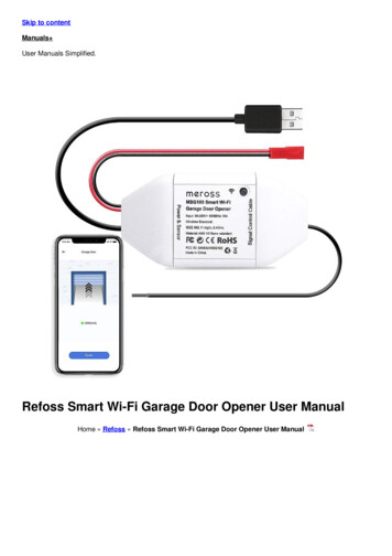
Transcription
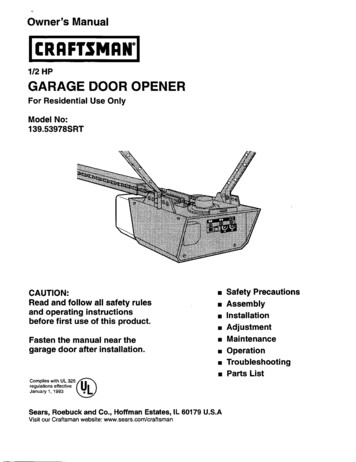
Owner'sManual1/2 HPGARAGE DOOR OPENERFor ResidentialUse OnlyModel No:139.53978SRTCAUTION:Read and follow all safety rulesand operating instructionsbefore first use of this product.[] Safety Precautions[] Assembly[] Installation[] Adjustment[] MaintenanceFasten the manual near thegarage door after installation.[] Operation[] Troubleshooting[] Parts ListComplies with UL 325 ,/" 'regulations effective U January 1, 1993Sears,Roebuckand Co., HoffmanEstates,IL 60179visit our Craftsman website: www.sears.com/craftsmanU.S.A
ContentsPageA review of safety alert symbols . 2You'll need tools. 3ContentsPageInstall the light and lens . 19Attach emergency release rope and handle . 19Safety information regarding garage door locksand ropes . 3Electrical requiramemts . 20Safety reversing sensor information. 21Testing your garage door for sticking, bindingand balance . 3Illustrationof sectional door installation . 4Install the safety reversing sensor. 22, 23Fasten door bracket (sectional door) . 24Fasten door bracket (one-piece door). 25Illush'ationof one-piece door installation. 5Connect door arm to trolley (sectional door). 26Carton inventory. 6Hardware inventory. 7Assembly section - pages 8 - 11Connect door arm to trolley (one-piece door) .27Adjustment section - pages 28 - 30Travel limit adjustments . 28Assemble the rail & install the trolley. 8Force adjustments . 29Fasten the rail to the opener . 9Test the safety reversing sensor . 30Install the idler pulley . 9Install chain/cable & attach the sprocket cover.10Tighten the chain . 11Installation section - pages 11 - 27Installationsafety instructions. 11Determine header bracket locationSectional door . 12One-piece door . 13Install the header bracket . 14Attach the rail to header bracket . 15Positionthe opener . 16Hang the opener . 17Install the door control . 18Test the safety reverse system . 30Operation safety instructions. 31Care of your opener . 31Maintenance schedule . 31Operation of your opener . 32Receiver and remote control programming . 33Having a problem? . 34, 35Repair parts, rail assembly . 36Repair parts, installation. 36Repair parts, opener assembly . 37Accessories. 38Index . 39How to order repair parts . 40Warranty . 40Start by reviewing these important safety alert symbolsMechanicalElectricalWhen you see this Safety Symbol on the following pages, it will alert you to the possibility of damageto your garage door and/or the garage door opener if you do not comply with the correspondinginstructions. Read the instructionscarefully.This garage door opener is designed and tested to offer safe service provided it is installed, operated,maintained and tested in strict accordance with the safety instructions contained in this manual.2
You'll Need ToolsDuring assembly, installation and adjustment of the opener, instructions will call for hand tools shown below.StepladdercketsAn unbalanced garage door might not reversewhen required and someone under the doorcould be seriously injured or killed.If your garage door binds, sticks or is out ofbalance, call for professionalgarage doorservice. Garage doors, door springs, cables,pulleys, brackets and their hardware are underextreme tension and can cause serious Injuryor death. Do not try to loosen, move or adjustthem youreelflRopes left on a garage door could causesomeone to become entangledand killed.Remove all ropes connected to the door beforeinstalling and operating the opener.Adjustable End WrenchTo avoid damage to the garage door andopener, disable locks before installing andoperating the opener. Use a wood screw or nailto hold looks in the "open" (unlocked) position.Operation at other than 120V 60 Hz will causeopener malfunction and damage.Before you begin, complete the following test tomake sure your door is balanced, and is notsticking or binding: Lift the door about halfway as shown. Release thedoor. It should stay in place, supported entirely byits springs.Identify the type and height of your door and anyspecial conditions that exist and any additionalmaterials that may be required by referring to thelists on page 4 or page 5. Raise and lower the door to see if there is anybinding or sticking.ONE-PIECE DOOR3
Before you begin, survey your garage area tosee whether any of the conditions below applyto your installation.FINISHED CEILINGSupport bracket &fastening hardwareis required.See page 17.Horizontal and vertical reinforcementis needed for lightweight garage doors(fiberglass, steel, aluminum, doorwith glass panels, etc.).See page 24 for details,Header WallExtensionSpdngAccess DoorORSpdngOsafetyReversingSer sorFloor must be levelSensoracross width of door,Closed PositionHeaderBracketBased on your particular requirements, there areseveral installation steps which might call formaterials and/or hardware not included in the carton./TrolleyStop BoltTrolley Step 1, page 12 - Look at the wall or ceiling abovethe garage door. The header bracket mustbesecurely fastened to structural supports. Step 5, page 17 - Do you have a finished ceiling inyour garage? If so, a support bracket andadditional fastening hardware may be required. Safety reversing sensor, page 21 - Dependingupon garage construction, extension brackets (seeAccessories page 38) or wood blocks may beneeded to fasten sensors to mounting locations. Step 10, page 22 - Floor mounting of the safetyreversing sensor will require hardware notprovided. Step 11, page 24 - Do you have a steel, aluminum,fiberglass or glass panel door? If so, horizontaland vertical reinforcement is required. Look at the garage door where it meets the floor.It must close on the floor all the way across.Otherwise, the safety reverse system may notwork properly. See page 30, Floor or door shouldbe repaired.u rHeaderWallGarageDoor -J-\JEnl 'l YRedaseDoorArmDoorBracket The opener can be installed within 4 feet to the leftor right of the door center if there is a torsion springor center bearing plate in the way of the headerbracket or door bracket area. If your door hasextension springs, the opener must be installed inthe center of the door. See pages 12 and 24. Do you have an access door in addition to thegarage doo If not, Model 53702 Emergency KeyRelease is required. See page 38. If your door is more than 7 feet high, see the railextension kits listed on page 38.You may find it helpful to refer back to this page as you proceed with the installation of your opener.
One-PieceBefore you begin, survey your garage area tosee whether any of the conditionsto your installation.Door withoutTrackFINISHED CEILINGbelow applysupportbracket"&fastening'h rdware is required.See page 17.HeaderWallTrolleyStop BoltCableTrolleyEmergenCyReleaseRope & HandleleaderReversincap between floor and bottomSafetyof door must not exceed 1/4".Reversing SensorSensor"-----One-Piece Door with TrackBased on your particular requirements, there areseveral installation steps which might call formaterials and/or hardware not included in the carton. Step 1, page 13 - Look at the wall or ceiling abovethe garage door. The header bracket mustbesecurely fastened to structural supports. Step 5, page 17 - Do you have a finished ceiling inyour garage? If so, a support bracket andadditional fastening hardware (not provided) maybe required. Safety reversing sensor, page 21 - Depending ongarage construction, wood blocks or extensionbrackets (see Accessories page 38) may beneeded to fasten sensors to mounting locations. Step 10, page 22 - Floor mounting of the safetyreversing sensor will require hardware that is notprovided. Step 11, page 25 - Generally, a one-piece doordoes not require reinforcement. If your door islightweight, you can refer to the informationrelating to sectional doors on page 24. Step 11, page 25 - Depending on your door'sconstruction, you might need additional mountinghardware for the door bracket.;afety. SafetyReversingSensoracross width of doorReversingSensorClosed Position/JJ/Trolley Stop BoltWall"Headeri ; Do you have an access door in addition to thegarage door? If not, Model 53702 Emergency KeyRelease is required. See page 38. The gap between the bottom of the garagedoor and the floor cannot exceed 1/4%Otherwise, the safety reverse system may notwork properly. See page 30. The floor or the doorshould be repaired.ChainCableRailB cketBracketBGEmergencyRelease-- Rope &HandleDoor ArmoorStraightarage Door-You may find it helpful to refer back to this pageas you proceed with the installation of youropener.5
Carton InventoryYour garage door opener is packaged in two cartons which contain parts illustrated below. Accessories willdepend on model purchased, if anything is missing, carefully check the packing material. Parts may be "stuck" inthe foam. Hardware for assembly and installation is shown on page 7.StandardControl ConsoleSecurity Keyless EntrySecurity-I- Three-FunctionRemote Control with Visor Clip (2)Ught LensTroneyRailCenter/BackSectionsSprocket CoverChainHanging BracketsIdler PulleyRailFront (header)SectionJDoor BracketCurved DoorArm SectionHeader Bracket2-Conductor Bell WireWhite & White/RedSafety SensorBracket(2) Safety Reversing Sensors(1 Sending Eye and 1 Receiving Eye)with2-Conductor White & White/Black Bell Wireattached6UteratureSafetyandLabels]Straight DoorArm Section
Separate all hardware from the packages in the rail carton and the opener carton, asshown below, for the assembly and installation procedures.ASSEMBLY@ @Lock Nut1/4"-20 (2)Lock Washer3/8' (1)ONut3/8" (1)UMasterLink(2)Bolt 1/4"-20 x 1-5/4" (2)Chain Spreader (2)Idler Bolt (1)TroUey Threaded Shaft (1)INSTALLATIOND,,,L,H,H,I,,,,,D 0Hex Screw5/16'-18x7/8" (4)Spacer (2)Nut5/16"-18 (8)Lock Washer5/16" (7)RingFastener ABx1-1/4 (2)]"HlJ::]:''"'"I6-32x1" (2)ojClevis Pin5/16"x1-1/2" (1)SAFETYREVERSINGCarriage Bolt1/4"-20xl/2" (2)CleVis Pin5/16"xl" (1)Wing Nut (2)omClevis Pin5/16"x1-1/4" (1)SENSORInsulatedStaples (20)Anchors (2)InsulatedStaples (10)
Assembly Section: Pages 8 - 11To avoid installation difficulties, do not run the garage door opener until instructed to do so.Assembly Step IAssemblethe Rail& InstallItheITrolleyThe front rail has a cut out "window"at the door end(see illustration). The hole above this window islarger on the top of the rail than on the bottom. Asmaller hole 3-1/2" away is close to the rail edge.The back rail has a similar hole close to the edge,about 4-3/4" from the far end. A 3-piece rail usestwo back rails.Preferred assembly is to position the rails rightside up, with the small holes along the sameedge.1. Remove the straight door arm and clevis pinpackaged inside the front rail and set aside forInstallation Step 12.2. Align the rail sections on a fiat surface exactly asshown and slide the tapered ends into the largerones. Tabs along the side will lock into place.3. Place the powerhead on packing material toprotect the cover, and rest the back end of the railon top. For convenience, put a support under thefront end of the rail.Trolley/4. As a temporary trolley stop, clamp a locking pliersonto the rail, 8" from the center of the idler pulleyhole, as shown.5. Check to be sure there are 4 black plastic wearpads inside the inner trolley. If they became looseduring shipping, check all packing material. Snapthem back into position as shown.6. Connect the inner and outer trolleys as shown.End7. Slide the trolley assembly along the rail from theback end to the locked pliers.Back Rails(TO POWERHEAD)EndOuter 18" Distar e fromIdler Pulley Hole\Locking PliersInner TrolleyIdJerHoleWindowCut-Out- Wear PadsFront Rail(TO DOOR)8
Assembly Step 2IIFasten the Rail to the Opener Insert a 1/4"-20xl -3/4 bolt into the coverprotection bolt hole on the back end of the rail asshown. Tighten securely with a 1/4"-20 lock nut.To fasten rail, use only those screws mountedin the top of the opener. Any other screws willcause serious damage to the opener. Remove the two screws from the top of theopener. Place the U bracket, flat side down, on the openerand align the bracket holes with the screw holes.Fasten with the previously removed screws. Attach spreaders to the U bracket by snappingthem into place.Screws OpenerSprocket"U" Bracket Align the rail assembly with the top of the opener.Slide the rail end onto the U-bracket, all the wayto the stops that protrude on the top and sides ofthe bracket.CoverSoHoSLIDE RAILTO STOPON TOP AND SIDESOF BRACKETHardware Shown Actual Sizeinto Back Slets.then Snap TabInto Front SlotLock NutBolt 1/4"-20 x 1-3/4AssemblyInstall1/4"-20Step 3the Idler PulleyChain andCabte Lay the chain/cable beside the rail, as shown.Grasp the end with the cable loop and passapproximately 12" of cable through the window.Allow it to hang until Assembly Step 5. Remove the tape from the idler pulley. The insidecenter should be pre-greased. If dry, regrease toensure proper operation. Place the idler pulley into the window as shown. Insert the idler bolt from the top through the railand pulley. Tighten with a 3/8" lock washer andnut underneath the rail until the lock washer iscompressed.TrolleyreaseInside PulleyIdlerPulleyRotate the pulley to be sure it spins freely.Idler PulleyInsert a 1/4"-20xl-3/4 bolt into the trolley stophole in the front of the rail as shown. Tightensecurely with a 1/4"-20 lock nut.Hardware Shown Actual SizeIdler BoltStop HoleBolt 1/4'-20 x 1-3/4Lock Nut 1/4"-20Nut 3/8'Lock Washer 318"'
Assembly Step 4Install the Chain/Cableand Attachthe SprocketCover1. Pull the cable around the idler pulley and towardthe trolley.2. Connect the cable loop to the retaining slot onthe trolley, as shown: From below, push pins of master link bar upthrough cable loop and trolley slot.DispensingCarton Push master link cap over pins and past pinnotches.Leave Chainand CableInside D spensingCarton to PreventKinking. Slide clip-on spring over cap and onto pinnotches until both pins are securely locked inplace.3. With the trolley against the pliers, dispense theremainder of the cable/chain along the rail towardthe powerhead and around the sprocket. Thesprocket teeth must engage the chain.Keep Chain and CableTaut When Dispensing4. Check to make sure the chain is not twisted, thenconnect it to the threaded shaft with theremaining master link.5. Thread the inner nut and lock washer onto thethe trolley shaft.6. Insert the trolley threaded shaft through the holein the trolley. Be sure the chain is not twisted.7. Loosely thread the outer nut onto the trolleyshaft.8. Remove the locking pliers.Master LinkClip-On Spdng9. Align the tabs on the sprocket cover with the slotsin the mounting plate. Squeeze cover and inserttabs in slots.Master UnkMaster.Unk CapMaster.- Unk CapCableTrolleyThreadedIdlerlottedIi Iqi erBarSprocketCoverFrontTab SlotOpenerSprocketBackTab SlotMounting10
AssemblyStep 5Tighten the ChainI Spin the inner nut and lock washer down thethreaded shaft, away from the trolley.Figure Io Lo Tro,.yNut Washer To tighten the chain, turn outer nut in the directionshown (Figure 1).ToT ., nOuterNut.-- I!Shaft/ When the chain is approximately 1/2" above thebase of the rail at its midpoint, re-tighten the innernut to secure the adjustment.Sprocket noise can result if chain is too loose.Inner NutWhen installation is complete, you may notice somechain droop with the door closed. This is normal. If thechain returns to the position shown in Figure 2 whenthe door is open, do notre-adjust the chain.Figure 2IChainr--.L.L .LLLJNOT . During future maintenance, AL WA YS pull theemergency release handle to disconnect trolley beforeadjusting chain.J--L --L L L JiI1/InchIBase o RaMid tength of RailNOTE: You may notice loosening of chain afterAdjustment Step 4 (Test the Safety Reverse System).Check for proper tension and readjust chain ffnecessary. Then repeat Adjustment Step 4.You have now finished assembling your garage door opener.warnings before proceedingto the installation section:Please read the followingIMPORTANT INSTALLATION INSTRUCTIONSTo reduce the risk of severe injury or death to persons:1. READ AND FOLLOW ALL INSTALLATION INSTRUCTIONS.2. Install only on a properly balanced and lubricated garage door. An Improperly balanced doormay not reverse and could result in severe injury or death. Repairs to cables, spring assembliesand other hardware must be made by a professional service person before installing opener.3. Disable all locks and remove all ropes connected to the garage door before installing the opener.Ropes connected to a garage door can cause entanglement and death.4. If possible, install door opener 7 feet or more above floor with the emergency release handlemounted 6 feet above the floor.5. Do not connect the opener to power source until instructed to do so.6. Locate the Door Control within sight of the door at a minimum height of 5 feet where smallchildren cannot reach and away from all moving parts of the door.7. Install the User Safety Instruction Label on the wall adjacent to the door control and theMaintenance Instruction Label in a prominent location on the inside of the garage door.8. Upon completion of the installation, the door must reverse when it comes in contact with aone-inch high object or a 2x4 laid flat on the floor.9. Do not wear watches, rings or loose clothing while installing or servicing an opener. Jewelry orloose clothing can be caught in the mechanism of the garage door or the opener,11
Installation Section: Pages 12 - 27Installation Step IDetermineHeaderBracketLocationIf the header bracket Is not rigidly fastened toa structural support on the header wall orceiling, the safety reverse system may notwork properly (see page 30). The door mightnot reverse when required, and could causeserious injury or death.Installation procedures vary according togarage door types. Follow the instructionswhich apply to your he garage door springs, cables, pulleys,brackets and their hardware are under extremetension. Do not attempt to loosen, move oradjust them yourself. Serious personal injuryor death could result. Call for professionalgarage door service.Structural Close the door and mark the insidevertical centerline of the garage door Extend the line onto the header wallabove the door.SupportsRemember, you can fasten theheader bracket within 2 feet of theleft or right of the door center onlyifa torsion spring or center bearingplate is in the way; or you can attachit to the ceiling (refer to page 14)when clearance is minimal. (It maybe mounted on the wall upside downif necessary, to gain approximately1/2".).VerticalIJ/f you need to install the header bracketon a 2x4 (on wall or ceiling), use lagscrews (not provided) to securely fastenthe 2x4 to structural supports as shownhere and on page 13.CeilingI 'Header Open your door to the highestpoint of travel as shown. Drawan intersecting horizontal lineon the header wall 2" abovethe high point This height willprovide travel clearance for thetop edge of the door.Door clearance brackets areavailable for sectional doorswhen headroom clearance isless than 2" See accessorypage 38.2wall'* HighHeaderTrackt Pointof TravelHighest Pointof TravelDOOrSectional doorwith curved trackProceedTrackto Step 2, page 14.12One-piece doorwith horizontal track
Read the Safety instructions on page 12. They also apply to doors without tracks.Header WallVerticalCenterflne2x4 Close the door and mark theinside vertical centerline ofyour garage door. Extend theline onto the header wallabove door.If headroom clearance isminimal, you can install theheader bracket on the ceiling.See page 14.[OPTIONAL CEILING MOUNTFOR HEADER BRACKET If you need to install theheader bracket on a 2x4 (onwall or ceiling), use lag screws(not provided) to securelyfasten the 2x4 to structuralsupports as shown.#JHeader WallHeaderWallJHighest Pointof TravelHighest Pointof Travel/Doorl8Jamb(3HardwareOne-piece door without trackjamb hardware Open your door to the highestshown. Measure the distancedoor to the floor. Subtract thedoor. Add 8" to the remainder.One-piece door without trackpivot hardwareEXAMPLEpoint of travel asfrom the top of theactual height of the(See Example).Distance from top of door(at highest point of travel) to floor . 92"Actual height of door . -88"Remainder .4" Close the door and draw an intersecting horizontalline on the header wall at the determined height.If the total number of inches exceeds the heightavailable in your garage, use the maximumheight possible, or refer to page 14 for ceilinginstallation.ProceedAdd . 8"Bracket height on header wall .12"(Measure UP from top of CLOSED door,)to Step 2, page 14.13
Installthe Header BracketInstallationStep 2You can attach the header bracket either to thewall above the garage door, or to the ceiling.Follow the instructions which will work best foryour particular requirements.IWall HeaderBracketInstallation Mark the vertical set of bracket holes. Drill 3/16"pilot holes and fasten the bracket securely to astructural support with the hardware provided. Center the bracket on the vertical guideline withthe bottom edge of the bracket on the horizontalline as shown (with the arrow pointing toward theceiling).2x4StructuralHeaderBracketSupportWall MountVerticalCenterLineSpdngsOptionaZMounting Holes.-/VerticalCenterUneHighest Point ofGarage Door TravelHardware Shown Actual SizeLag n Extend the vertical guideline onto the ceiling asshown. Center the bracket on the vertical mark, no morethan 6" from the wall. Make sure the arrow ispointing toward the wall. The bracket can bemounted flush against the ceiling when clearanceis minimal. Mark the side holes, Drill 3/16" pilot holes andfasten bracket securely to a structural support withthe hardware provided.VerticalCenter LineCeilingMounting Holes6" MaximumDoor SpringVerticalCenter Une14
Attachthe Rail to the HeaderInstallationStep 3BracketINOTE: (Optional) With an existing Craftsmaninstallation, you may re-use the old header bracketwith the two plastic spacers included in the hardwarebag. Place the spacers inside the bracket on eachside of the rail, as illustrated. Position the opener on the garage floor below theheader bracket. Use packing material as aprotective base.If the door spring is in the way you'll need help.Have someone hold the opener securely on atemporary support to allow the rail to clear thespring. Position the front rail end within the header bracketand join with a 5/16"xl-1/2" clevis pin as shown.Header BracketIdler Pulley Insert a ring fastener to secure.MountingHoleExistingHeader BracketExistingClevis PinSpacerMountingHoleOPTION WmHEXISTING CRAFTSMANINSTALLATIONHardware Shown Actual SizeolOClevis Pin 5/16"xl -1/2"15Ring fastener
Installation Step 4Positionthe OpenerFollow instructionstype as illustrated.which apply to your doorA 2x4 laid flat is convenient for setting an idealdoor-to-T-rail distance.Outer TrolleyInner Trolley Raise the opener onto a stepladder as shown, Youwill need help at this point if the ladder is not tallenough. Open the door all the way and place a 2x4 laid flaton the top section beneath the rail.DoorIf the top panel hits the trolley when you raisethe door, pull down on the trolley release arm todisconnect the inner and outer sections. Thetrolley can remain disconnected until Step 12 iscompleted.TrolleyTrolleyWith the door fully open and parallel to the floor,measure the distance from the floor to the top ofthe door.Using a stepladder as a support, raise the openerto this height (it will be at a slight angle as shown).The top of the door should be level with the top ofthe opener. Do not position the opener more than2" above this point.162x4
IInstallation Step 5HangtheOpenerTwo representative installations are shown. Yoursmay be different. Hanging brackets should beangled, Figure 1, to provide rigid suppod. Onfinished ceilings, Figure 2, attach a sturdy metalbracket to structural supports before installing theopener. The bracket and fastening hardware are notprovided. See accessory page 38.1. Measure the distance from each side of theopener to the structural support.Figure ISupports2. Cut both pieces of the hanging bracket torequired lengths.5/16"- 18xl -7/8"3. Drill 3/16" pilot holes in the structural supports.Mea ur\\Distance4. Attach one end of each bracket to a support with5/16"-18xl-7/8" lag screws.5. Fasten the opener to the hanging brackets with5/16"-18x7/8" screws, lock washers and nuts.6. Check to make sure the T-rail is centered overthe door (or in line with the header bracket if thebracket is not centered above the door).5/16"-18x7/8" Screw5/16' Lock Washer5/16"-18 Nut7. Remove the 2x4. Operate the door manually. Ifthe door hits the rail, raise the header bracket.Figure 2NOTE: Do NOT connect power to opener at thistime.HiddenI-Support -- .//""-. " 5/16"-18xl-7/8"Bracket(Not Suppl5/16"-18x7/8'Screw5/16" LOckWasherLi,i,5/16"18xl -7/8"FJL!jlI! !!HD 5/16"o 18x7/8"Nut 5/16"-18Lock Washer 5/16"17/t S-j::;'s' c''" "Hardware Shown Actual Size-Lag Screws- - "- -- -.(NOt Provided)5/16"-18x7/8" Screw5/16" LOck Washer5/16"-18 Nut
IInstallation Step 6Install the Door ControlLocate the door control within sight of the door at aminimum height of 5 feet where small childrencannot reach, and away from all moving parts of thedoor and door hardware.The door control is typically attached directly to thewall. If installing into drywall, drill 5/32" holes anduse the anchors provided. For pre-wired installations(as in new home construction), Console modelsmay be mounted to a standard single gang box(Figure 2).1. Strip 1/4" of insulation from one end of the bellwire and connect it to the two screw terminals onthe back of the door control: white to 2 andwhite/red to 1.2. Pry off cover along one side with a screwdriverblade (Figure 1). Fasten with 6ABx1-1/4" selftapping screws (standard installation) or 6-32x1"machine screws (pre-wired installation) asfollows:Do not connect to live electrical wiling. Connectonly to 24 Volt/oH, voltage wires. Connection tolive wires or higher voltage may cause seriousinjury from shock, burn or electrocution.Children operating or playing with a garagedoor opener can injure themselves or others.The garagedoor could close and causeserious injury or death.Install the door control (or any additional pushbuttons) out of the reach of children and awayfrom all moving parts of the door and doorhardware, but where the garage door is visible.Do not allow children to operate the pushbutton(s) or the remote control(s).A moving garage door could injure someoneunder it. Activate the opener only when thedoor is properly adjusted, you can see it clearly,and there are no obstructions to door travel.Hardware Shown Actual Size Install bottom screw, allowing 1/8" to protrudeabove wall surface.6AB x 1-1/4" ScrewUihJIlnJIlililililIliln Position bottom of door control on screw headand slide down to secure. Adjust screw for snugfit.InsulatedStaplesControl Console (std installation) Install top screw with care to avoid crackingplastic housing. Do not overtighten.Control Console (pre*wired)Dry Wall Anchors Insert top tabs and snap on cover.Figure 13. (For standard installation only) Run the bell wireup the wall and across the ceiling to the opener.Use insulated staples to secure the wire inseveral places. Be careful not to pierce the wirewith a staple, creating a short.4. Connect the bell wire to the terminal screws onthe opener panel: white to 2; white/red to 1.5. Position the antenna wire as shown.Figure 2REMOVE & REPLACE COVERTo Replace,InsertTop Tabs. First PRE-WlREDINSTALLATIONTo Remove,TwistHere 24 Volt2-CondustorBell Wire2-
Do you have an access door in addition to the garage door? If not, Model 53702 Emergency Key Release is required. See page 38. The gap between the bottom of the garage door and the floor cannot exceed 1/4% Otherwise, the safety reverse system may not work properly. See page 30. The floor or the door should be repaired.;afety Reversing